Project 1
Objective:
>Developing an Double-acting actuator model in SIMULINK using Simscape blocks.
>The mechanical system of the cylinder needs to be built using Simscape Multibody system and the hydraulic system needs to be modelled using Simscape Hydraulics system.
What is Double-acting actuator:
>An actuator is a device that works in conjunction with a valve to automate the process of stroking that valve. Without such a device, all valve operation would prove a manual exercise wherein every valve would require the direct physical manipulation of a lever, handwheel, gear operator, or similar item in order to open or close the flow path each time a process required the valve to stroke.
>In a double acting setup, the design requires the force of the instrument air pressure to both thrusts the pistons apart as well as to push the pistons together. In other words, this design requires supplied air to complete both the actions of opening and closing the subject, hence the term double acting valve. This function utilizes two air supply ports integrated into the design of the housing.
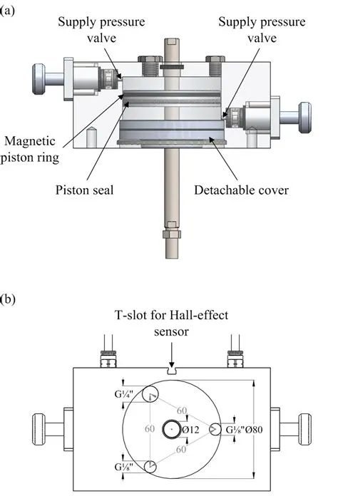
>One port allows air to access the chamber between the two pistons. Supplying sufficient air pressure here will force the pistons apart and rotate the pinion in one direction. The second port allows air to access the space on the opposing faces of the pistons. Supplying air pressure here, will push the pistons together and rotate the pinion in the opposite direction.
>Oftentimes, a valve assembly may include the installation of a solenoid to govern the supply air to these ports so that an electric signal may govern the opening and closing of the valve by means of this solenoid actuator interface.
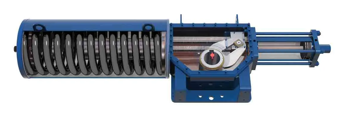
>>Hydraulic actuators use liquid as a means to apply pressure to the actuator’s mechanical components. They can exert a large amount of force because liquid is not compressible but are generally limited in acceleration and speed. Hydraulic actuators are available in spring-return and double-acting designs.


>In a frame network, the World frame is the ultimate reference frame. Directly or indirectly, all other frames are defined with respect to the World frame. If multiple World Frame blocks connect to the same frame network, those blocks identify the same frame. If no World Frame block connects to a frame network, a copy of an existing frame, frozen in its initial position and orientation, serves as the World frame.
3.Joints:
a.Revolute Joint

>Represents a revolute joint acting between two frames. This joint has one rotational degree of freedom represented by one revolute primitive. The joint constrains the origins of the two frames to be coincident and the z-axes of the base and follower frames to be coincident, while the follower x-axis and y-axis can rotate around the z-axis.
>In the expandable nodes under Properties, specify the state, actuation method, sensing capabilities, and internal mechanics of the primitives of this joint. After you apply these settings, the block displays the corresponding physical signal ports.
b.Weld joint:

>This block represents a joint with zero degrees of freedom. It contains no joint primitives. Base and follower frames, each connected to a separate rigid body, are coincident for all time. The block dialog box provides sensing options for constraint and total forces and torques.
c.Prismatic joint

>The Prismatic Joint block has only one prismatic primitive, which is along the z-axis of the base frame. During simulation, the z-axes of the base and follower frames align, and the follower frame moves with respect to the base frame along the z-axis.
Joint Degrees of Freedom

4.Rigids:

>Defines a fixed 3-D rigid transformation between two frames. Two components independently specify the translational and rotational parts of the transformation. Different translations and rotations can be freely combined.
>In the expandable nodes under Properties, choose the type and parameters of the two transformation components.Ports B and F are frame ports that represent the base and follower frames, respectively. The transformation represents the follower frame origin and axis orientation in the base frame.
5.Solids:
a.Extruded Solid:

>Represents a solid combining a geometry, an inertia and mass, a graphics component, and rigidly attached frames into a single unit. A solid is the common building block of rigid bodies. The Solid block obtains the inertia from the geometry and density, from the geometry and mass, or from an inertia tensor that you specify.
>In the expandable nodes under Properties, select the types of geometry, inertia, graphic features, and frames that you want and their parameterizations.
b.Brick Solid:

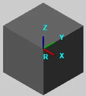
>The Brick Solid block is a prismatic shape with geometry center coincident with the reference frame origin and prismatic surfaces normal to the reference frame x, y, and z axes.
>The Brick Solid block adds to the attached frame a solid element with geometry, inertia, and color. The brick solid element can be a simple rigid body or part of a compound rigid body—a group of rigidly connected solids, often separated in space through rigid transformations.
c.Cylindrical Solid:

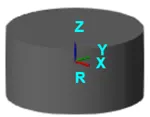
>Represents a solid combining a geometry, an inertia and mass, a graphics component, and rigidly attached frames into a single unit. A solid is the common building block of rigid bodies. The Solid block obtains the inertia from the geometry and density, from the geometry and mass, or from an inertia tensor that you specify.
>In the expandable nodes under Properties, select the types of geometry, inertia, graphic features, and frames that you want and their parameterizations.
d.Spherical solid:

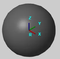
>The Spherical Solid block adds to the attached frame a solid element with geometry, inertia, and color. The solid element can be a simple rigid body or part of a compound rigid body—a group of rigidly connected solids, often separated in space through rigid transformations.
>Geometry parameters include shape and size. You can choose from a list of preset shapes or import a custom shape from an external file in STL or STEP format. By default, for all but STL-derived shapes, the block automatically computes the mass properties of the solid from the specified geometry and either mass or mass density.
e.Revolved Solid:


>The Revolved Solid block adds to the attached frame a solid element with geometry, inertia, and color. The solid element can be a simple rigid body or part of a compound rigid body—a group of rigidly connected solids, often separated in space through rigid transformations.
>Geometry parameters include shape and size. You can choose from a list of preset shapes or import a custom shape from an external file in STL or STEP format. By default, for all but STL-derived shapes, the block automatically computes the mass properties of the solid from the specified geometry and either mass or mass density
Subsystems:
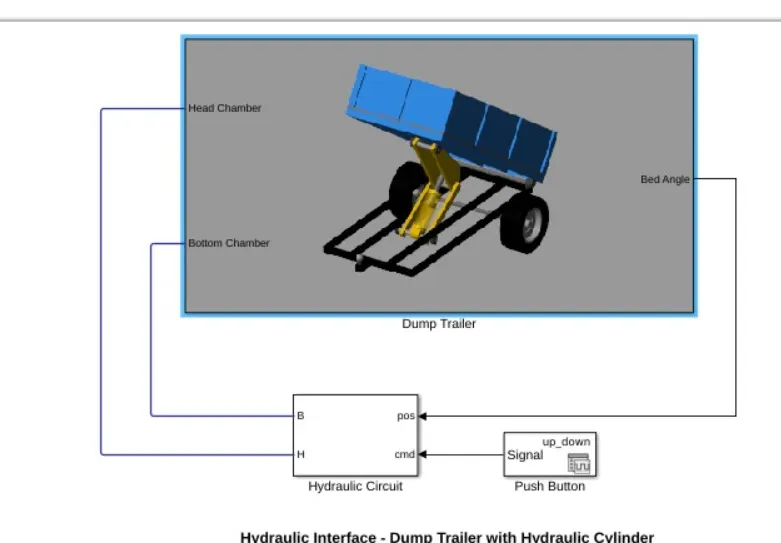
>By using the above provied simscape bolcks we are going to model the mechanical subsystem of dump trailer which is explained below;
>>Dump Trailer:
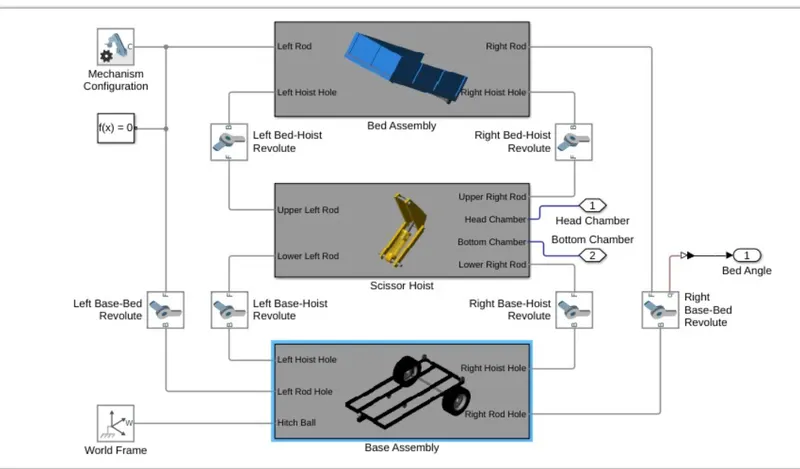
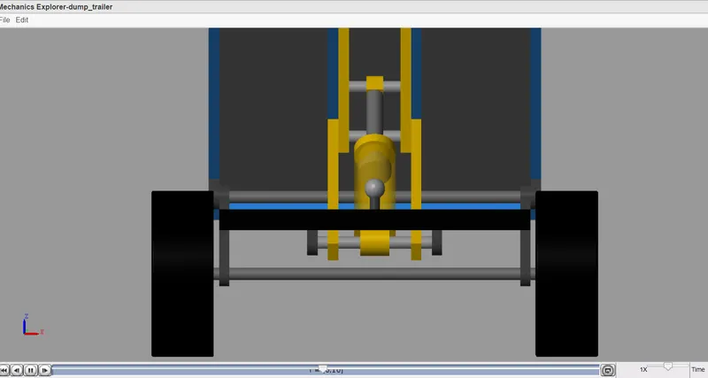
> Here the bed assembly and base assembly are purely contains simscape bolcks and the hoist is an combination of siumlin and simscape blocks.
1.Bed Assembly Subsystem:
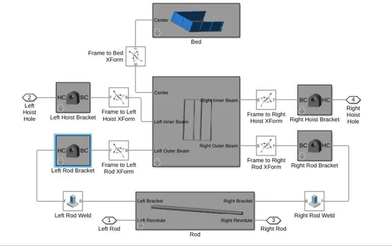
>Here bed assembly subsystem consists of an bed,fame,rod,brackests which are joined by using the weld joints.
Bed Subsystem:
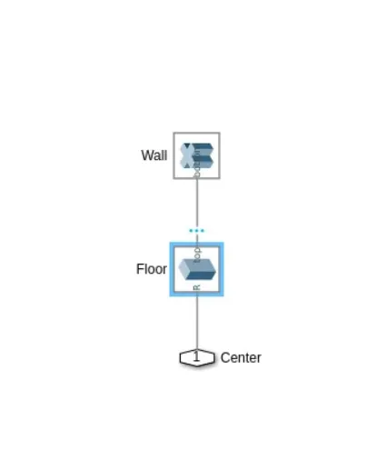
>Here the bed is builted by the blocks using extrusion and brick solid blokcs,which are attached to the frame by using joints.
Frame:
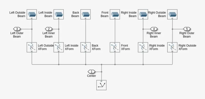
>The frame is builted by using the brick solid blocks and are connected to the rigids to transform the moments and the frame is connected to rod which is acted as intermediated to the system.
Rod:
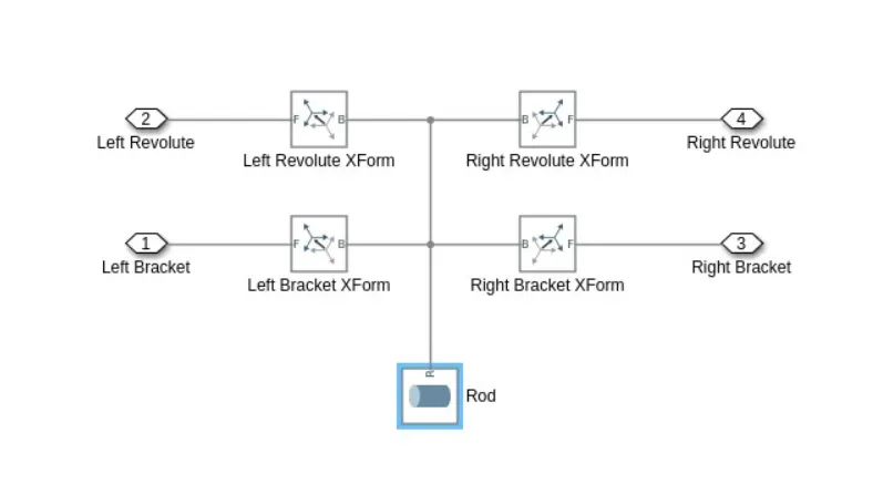
>The rod subsystem is builted by using the cylindrical solid block and are attached to the rigid transforms.
Hoist Brackets:
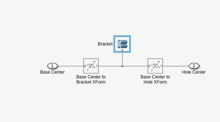
>Here the brackets are builded by using the extrude solid blocks,here we are using the four brackets on left of two are connected to the frame inner and outer beams respectivley, right two are connected to the right side of frame as inner and outer beams and the outer side of both brackets are attched to the rod by using weld joints.
2.Scissor Hoist:
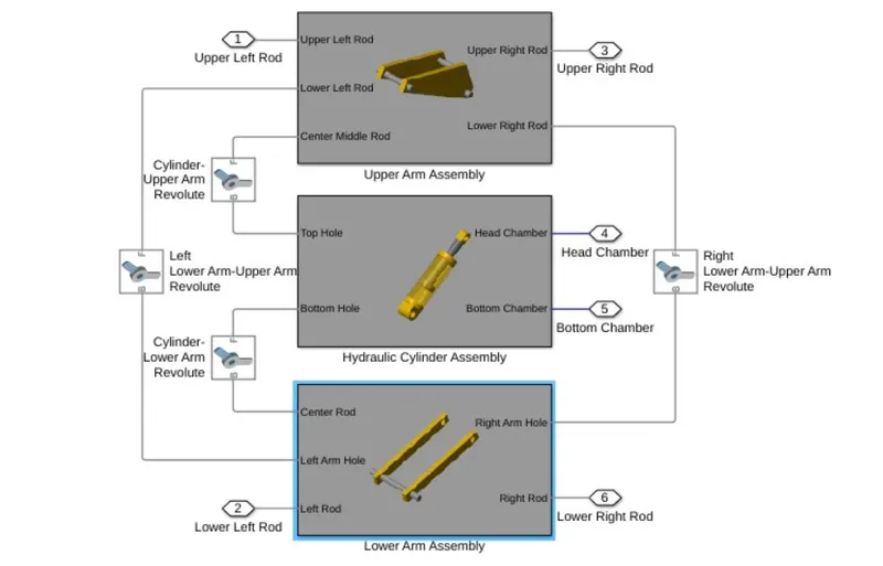
>The Scissor hoist contains the upper and lower arm assembly which is connected by the hydraulic system which is an simulink model and the arms are connected by using the revlouted joints.
Upper Arm Assembly:
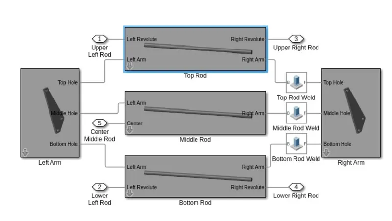
>Here the arm is splited into to the upper and lower arm assembly and we are going to discussed about the one arm assembly,which is consisting of two arm on both side of rod as left and right arm and the arm is provided by the three holes susch as top,middle and bottom which are connected to the three rods.on the right side of the arm are connected by using the welded joints .
Arms:
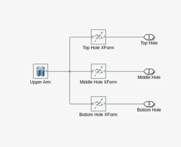
>Here the arms are buited by using the extruded solid block and are connected by using the rigid transform bolcks,here the left and right arms used on both sides.
Lower Arm Assembly:
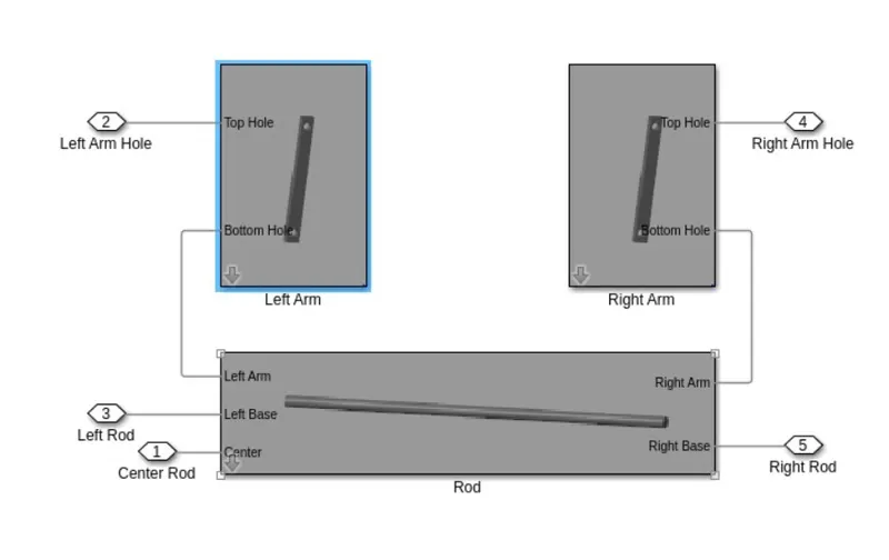
>The lower arm assembly is builded by using the two arms such as left and right arm are connected to the rod .here the arm fucntions same as mentioned in the upper arm assembly.
3.Base Assembly:
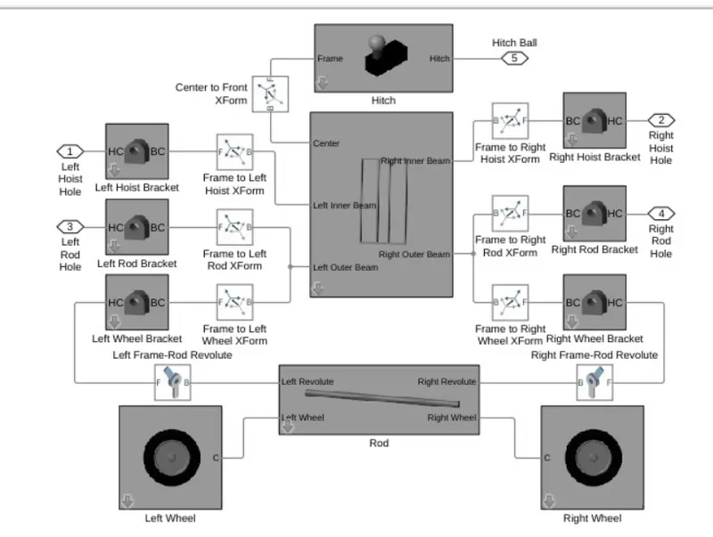
>The Base assembly consisting of an hitch and rod subsystem which are attached by using the frame and are joined by using the revolve joints.
Hitch:
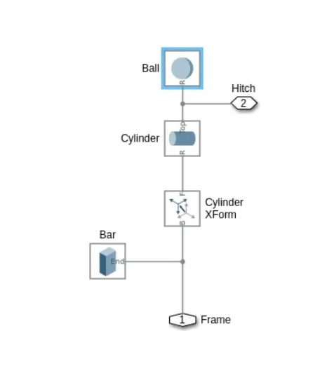
>The system is consisting of an circular,cylindrical and brick solid blocks.
Wheels:
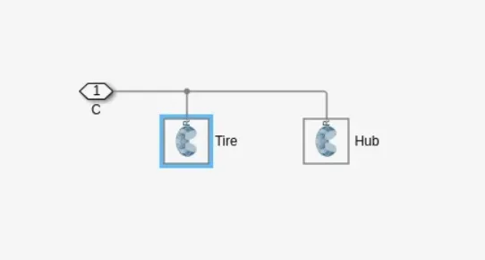
>The wheels are builed by using the revolved solid blocks,functions as a solid combining a geometry, an inertia and mass, a graphics component, and rigidly attached frames into a single unit. A solid is the common building block of rigid bodies. The Solid block obtains the inertia from the geometry and density, from the geometry and mass, or from an inertia tensor that you specify.Here the wheels are attached to the rod by using the revolved joints.
Double Acting Cylinder:
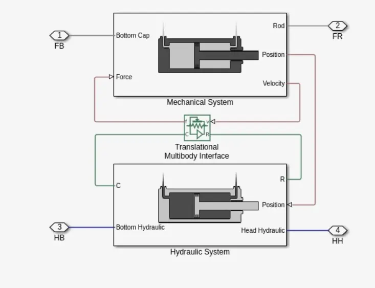
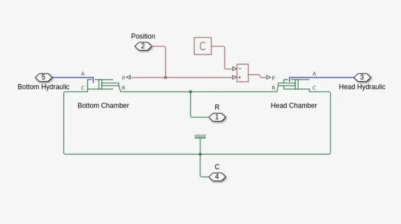
>The Double-Acting Hydraulic Cylinder block in the scissor hoist contains mechanical and hydraulic subsystems
Translational Multibody interface:

>The Translational Multibody Interface block implements an intuitive way to connect Simscape™ blocks that have mechanical translational ports with Simscape Multibod joints that have prismatic primitives. Simscape blocks that can be connected to a Translational Multibody Interface block,
The Translational Multibody Interface block matches the force and relative velocity across the interface. You can connect it to any Simscape Multibody joint that has a prismatic primitive:
-
Enable the velocity sensing port v and the force actuation port f on the joint. If the joint has multiple degrees of freedom, make sure that the selected velocity sensing and force actuation correspond to the same degree of freedom.
-
Connect physical signal ports v and f of the Translational Multibody Interface block to ports v and f of the Simscape Multibody joint.
-
Connect ports C and R of the Translational Multibody Interface block to a Simscape mechanical translational network.
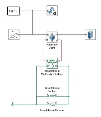
>>>>Mechanical Subsystem:
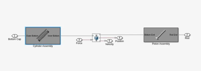
>The mechanical subsystem models the piston and barrel. A Prismatic Joint block provides the translational degree of freedom needed for piston extension and retraction. The piston's range of motion is constrained using joint limits.
>In addition, both of the converter blocks are configured to accept a physical position signal from the prismatic joint. These connections ensure that the state of the hyraulic chambers in the converter blocks are always consistent with the state of the prismatic joint.
Cylinder Assembly:
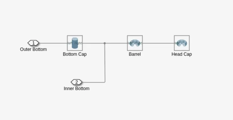
>The cylinder assembly block consisting of cylinder solid block and revolved solid blocks the cylinder assembly is connected to the piston assembly by prismatic joints.
Piston Assembly:
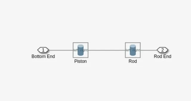
>The psiton assembly block is builded by using the cylindrical solid block which function as solid combining a geometry, an inertia and mass, a graphics component, and rigidly attached frames into a single unit. A solid is the common building block of rigid bodies. The Solid block obtains the inertia from the geometry and density, from the geometry and mass, or from an inertia tensor that you specify.
>>>Hydraulic System (Simscape Blocks Required) :
1.Translational Mechanical Converter:
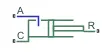
>The Translational Mechanical Converter (IL) block models an interface between an isothermal liquid network and a mechanical rotational network. The block converts isothermal liquid pressure into mechanical force and vice versa. It can be used as a building block for linear actuators.
2.PS Constant:

>The PS Constant block generates a physical signal of a constant value. You specify the value and unit of the signal as the constant parameter.