Project 1
ALL THE FILES OF PROJECT 1 IS ATTACHED IN THE ATTACHMENT
AIM:
To Route the Wiring harness on Given Engine and Prepare flatten view drawing in CATIA V5. Apply all Packaging rules, Industry best practices studied in this course. Apply Protection coverings as required.
To Prepare & Submit all necessary reports like clearance, Clipping/Clamping selection, Harness fixing requirements, Harness continuity, Assumptions if any along with CATIA 3D data.
SOLUTION :
- All the Connectors, Mounting Equipments and Engine files downloaded.
- We have downloaded all the igs zip files
- All the zip files are extracted
- Open the CATIA software and convert the files to CAT parts
- All the Connectors are electricaly defined with the below steps
- Part body is opened and points are created for bundle entry
- Mating points are also created along with the axis definition
- For channel External curve is drawn
- we then switch to electrical part design
- We define the parts as connectors, Mounting Equipments and cavity as per the use
- We define the point and bundle entry point
- Connection connector point is also made.
- Cavity Connection point axis is also made.
- This is done for all the connectors,Mounting Equipments and cavity.
- Hence it is electricaly defined.
- We then create a catalog for this challenge and all the components.
- Here are few photos of the steps.
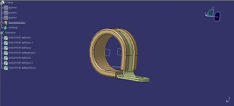
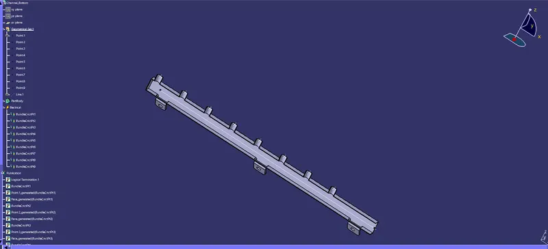
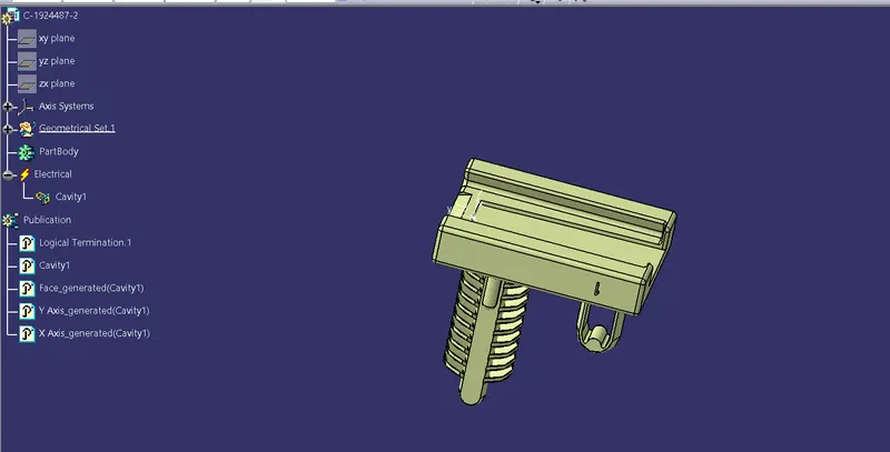
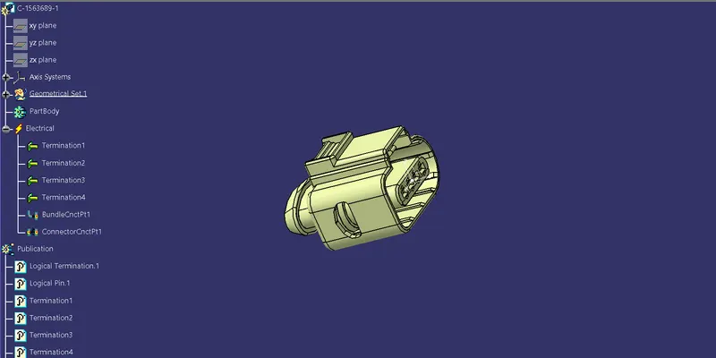
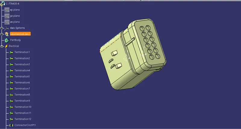
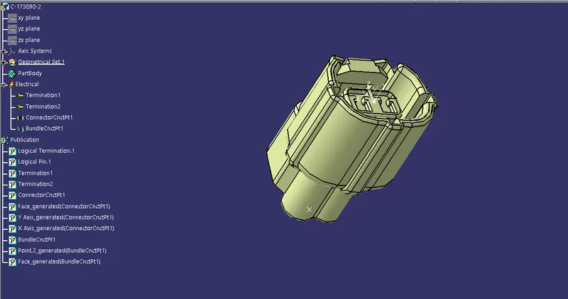
- New product is opened and it is named as Assembly Engine Harness Context

- Engine is added in the tree by copy paste
- New Product is created and named as Assembly Engine Geomentric bundle
- It is defined as geomentric bundle. Note the symbol has changed now.
- We add all the connectors, Mounting equipments here
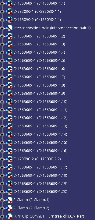
- The components are aligned as per needed.
- We use various commands to rotate and move.
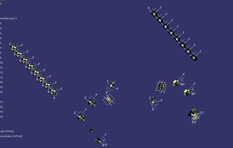
- Multi branchable is added to the geomentrical bundle
- Connectors are routed with the branch bundle by clicking the connectors
- To add sub branches Branch point is created on the main line.
- Then branches are routed to the connectors as per the question
- Tangency are changed to give a good curvature to the harness bundle
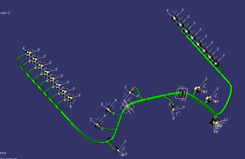
- Protective covering is applied to the branches
- New COT Tube is created and added to our catalog previuosly created
- It is then applied to the branches by clicking the branch and applying the COT tube.
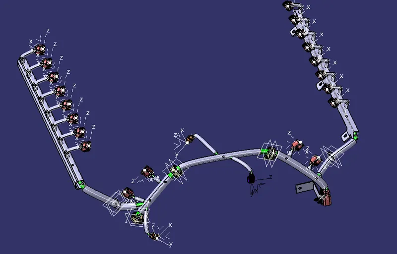
Bundle Flattening:
- Open a new product file
- Change the tool settings
- Open Wiring harness Flattening
- Harness flatenning parameters are defined.

- Keep Drawing tab as shown below
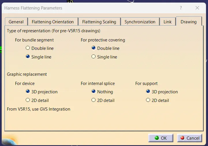
- Click extract and click the face of the Back door harness connector

- It will be added as Ehf in the tree structure
- Click flatten and click any face and click the bundles so the harness will flatten
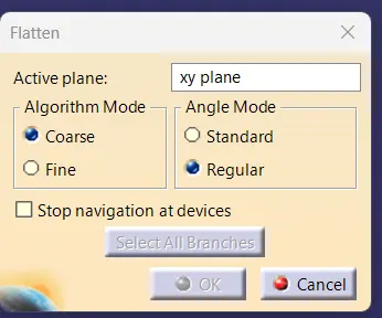
- Use commands to arrange the bundle
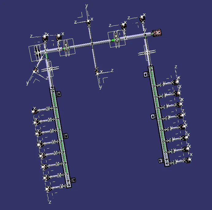
- We then open new drawing file
- Set ISO Standard and A0 as scale
- Click front view command and switch to the flatten window and click the face
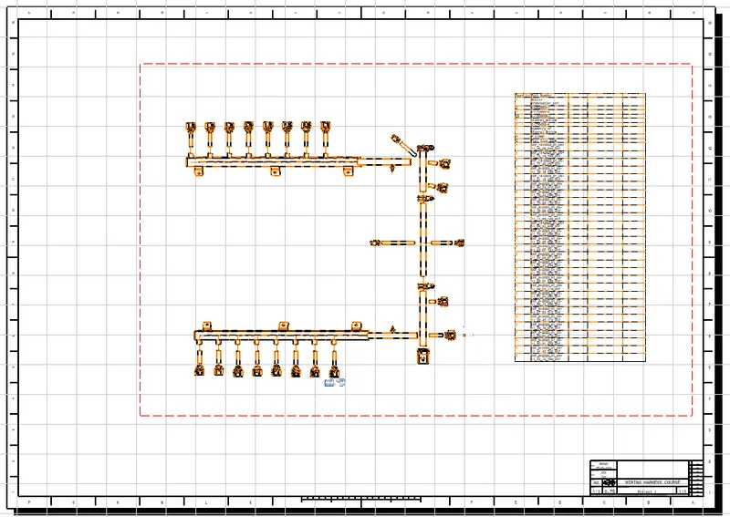
- now the drawing will come to the drawing sheet.
- Orient accordingly and click the properties
- In view tab select as per the below photo
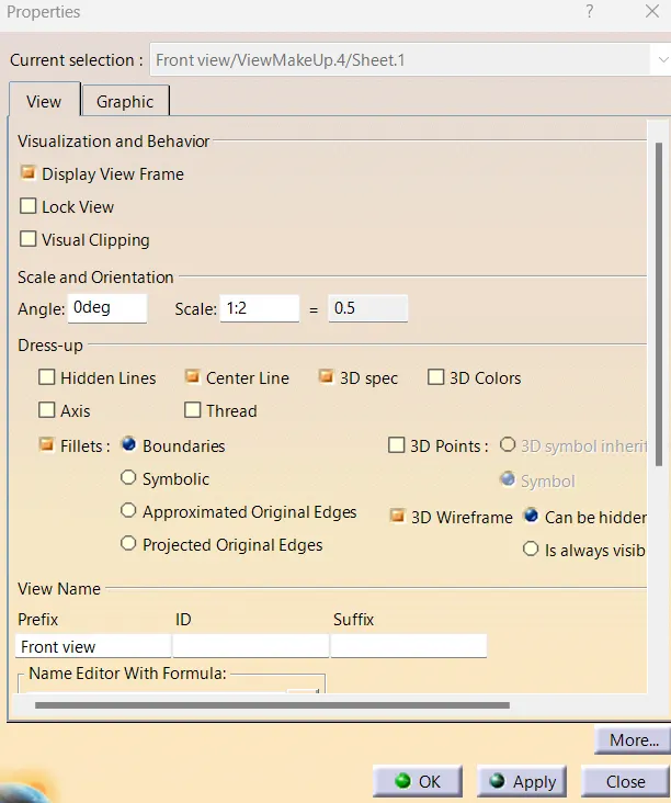
Thus the drawing we have attained