Project 1
OBJECTIVES:
- Define the mechanical components electrically and prepare the catalogue for the same
- Provide proper routing of bundle without and interference and also provide support parts like clips and clamps
- Creating the flattening file using flatteing workbench and create the 2D drawing using Drafting workbench
Answer:
Define the mechanical components electrically:
Initially choose the mechanical components for the engine wiring harness, following connectors has been used in the wiring harness.
- C-173090-2POLE CONNECTOR
- C-282080-1-2POLE CONNECTOR
- C-776438-4-INTERCONNECTOR
- C-1563689-1-4POLE CONNECTOR
- C-1924487-2-CAVITY CLIP
- Channel Bottom
- Channel top
- Furr tree clip
Then the next step is to define the above components electrically using following steps.
- First step is to create the parameters of the all mechanical connectors using mechanical part workbench.
- Next step is to create bundle connection point and create connector connection point.
- Then create connector connection axis, where Y axis facing towards connector entry and X axis toward locking mechanism.
- Then define the connectors electrically using electrical part workbench.
- First step is define the connector and terminals using connector option.
- Then Define bundle connection point option to define bundle entry position.
- Then Define connector connection point option to define connector entry point.
- Then add all the connectors, clips in the catalog
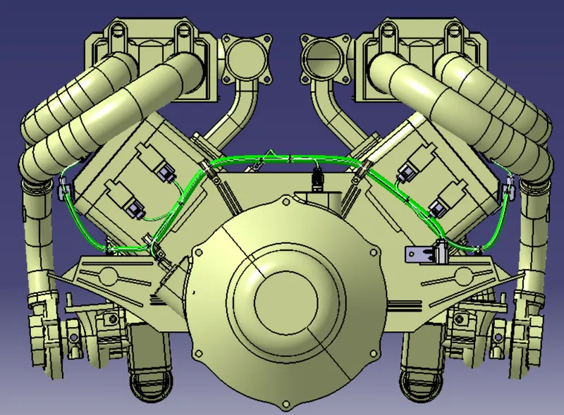
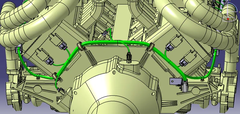
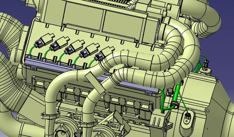
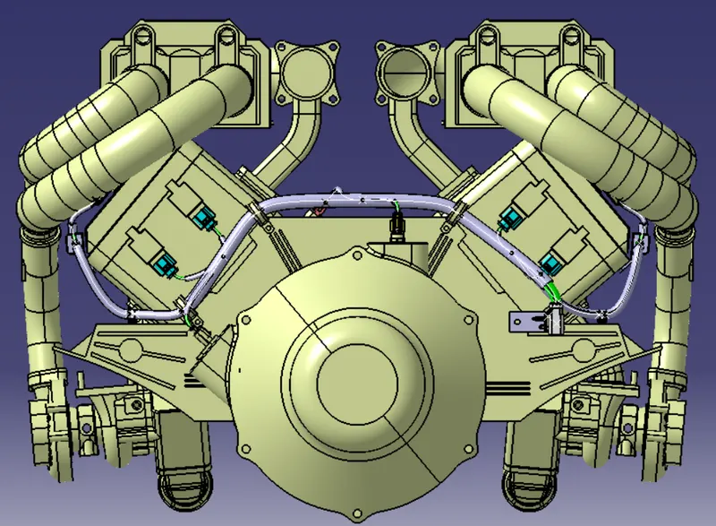
Engine wiring harness routing:
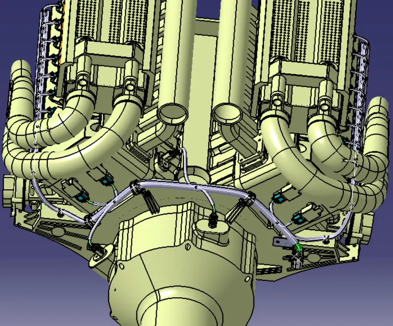
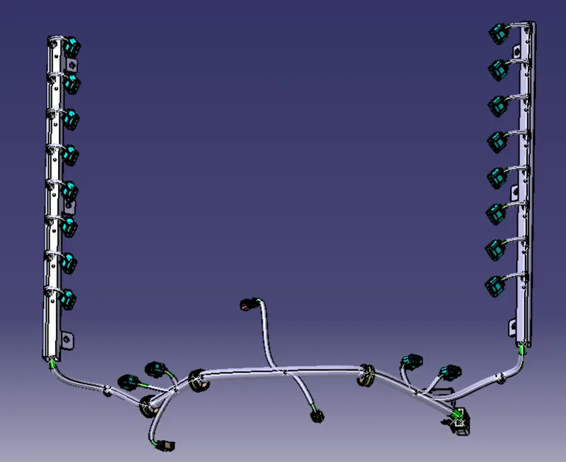
- Initial step for creating engine bundle routing is arranging the connectors and supporting clips in the desired locations using part assembly workbench tools.
- Then add all the connectors in the geometrical bunde assembly file using existing file option or add using catalog browser option from part assembly workbench.
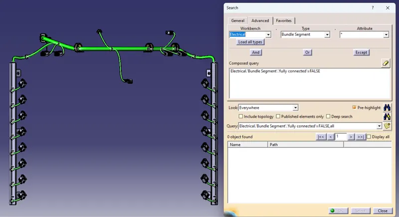
- After arranging the connectors in the desired location the next step is to create routing.
- For that define the assembly by electrical using geometrical bundle option from electrical harness assembly workbench and select the assembly product file.
- For creating routing we have to select multi branchable document option from electrical harness assembly work bench.
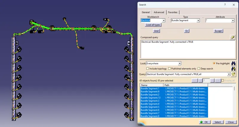
- Then the multi branchable file is created, Then provide the appropriate bundles in the connector.
- Add branch point option to create branch points in the bundle and given the appropriate bundles in all connectors.
- All the wiring harness has been followed the clearance management.
Creation of Bundle Flattening:
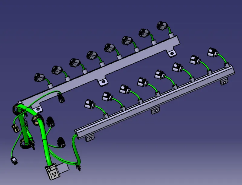
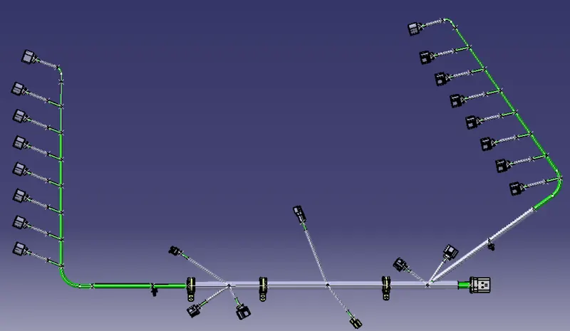
- After completing wiring harness routing next step is Bundle flattening, It has been done from electrical flattening workbench.
- Initial step is to set the Harness flattening parameters using harness flattening parametes option.
- Then next step is to extract Geometrical bundle assembly file from tile vertical window.
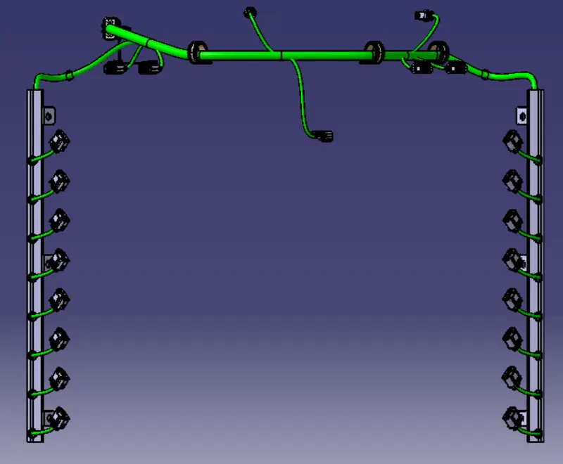
- Then next step is flatten the bundle using flatten option, where have to select the plane and choose the bundles for flattening and click ok.
- Then have to arrange the connectors using rotate command.
Creation of Harness Flattening Drawing:
- After creating Flattening of harness next step is 2D drawing creation, It has been created from Drawing workbench.
- Initial step is to select the front view of the harness flattern assembly, then click ok.
- Then adjust the drawings as per the parameters from properties option.

Conclusion:
Defined the mechanical components electrically and prepare the catalogue for the same has been completed. Provided proper routing of bundles and provided support parts like clips and clamps in desired positions. Then created the flattening file using flatteing workbench and created the 2D drawing using Drafting workbench.