Project 1
Aim:
Route the Wiring harness on Given Engine and Prepare a flattened view drawing in CATIA V5. Application of all Packaging rules, Industry best practices studied in this course shall be demonstrated in design. Apply Protection coverings as required.
Available connector 3D data can be used, or you can download the connectors from www.te.com
Prepare & Submit all necessary reports like clearance, Clipping/Clamping selection, Harness fixing requirements, Harness continuity, and Assumptions if any along with CATIA 3D data.
- Identifying all the electrical components. These components are external elements for the wire harness assembly. These are external geometry for the wiring harness. Even though they are electrical components, they are not going to be part of the wiring harness assembly or geometrical bundle assembly. They are part of the context assembly as they are the external geometry for the wiring harness.
- Finding the right connectors for those components.
Electrical components which are already attached to the engine :
- Injectors --> 8 on left side + 8 on right side
- Cam Shaft Sensors --> 4
- Coolant Temperature Sensor --> 1
- Transmission Neutral Sensor --> 1
Connectors for each of the above components:
- Injectors and Cam Shaft Sensors --> 4 pole connectors
- Coolant Temperature Sensor --> 3 pole connectors
- Speed sensor and Neutral Sensor --> 2 pole connectors
If any connector is not available then pseudo connectors have been used in this design
Steps involved :
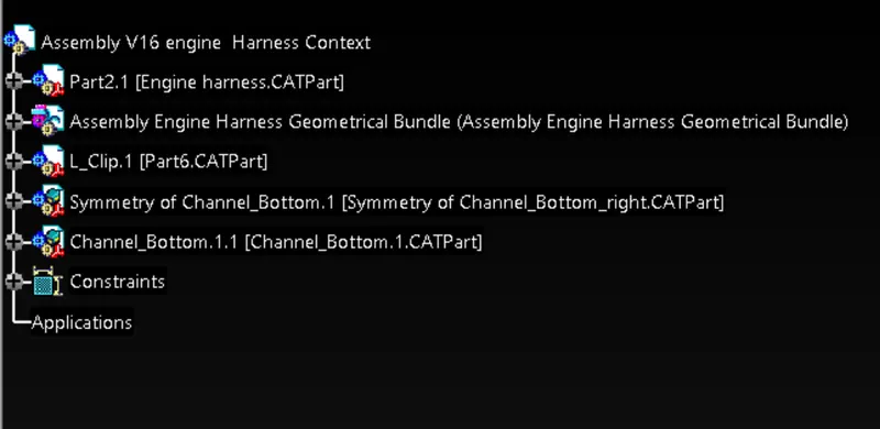
- Context Assembly for the engine harness was created which will act as the main assembly of the design and named Assembly V16 engine Harness Context. All the parts which are not part of the bundle are assigned to this like the channel and L-clip and engine model.
- Under the context assembly, the geometrical bundle assembly was created and named as Assembly Engine Harness Geometrical Bundle. All the parts which are part of the bundle are assigned to this like the connectors, fir tree clip, and wire bundle.
Connecting the sensors with connectors:
Injectors:
- 4-pole connector was connected with an injector using the compass, manipulation, and smart move commands. This step was repeated till all the injectors were connected with the 4-pole connector.
Cam Shaft Sensors:
- 4-pole connector was connected with a Cam Shaft Sensor using the compass, manipulation, and smart move commands. This step was repeated till all the Cam Shaft Sensors were connected with the 4-pole connector.
Coolant Temperature Sensor:
- A pseudo sensor was connected with a Coolant Temperature Sensor using the compass, manipulation, and smart move commands. Pseudo connector was used as a 3-pole connector was not available while routing.
Speed Sensor and Neutral Sensor:
- 2-pole connectors were used to connect with each of them.
Each of the above connectors was electrically defined using the "Define Connector" command and the bundle entry point was given using the "Define Bundle Connection Point" command. This was done in the "Electrical Part Design" workbench.
Bundle Connection:
- For the bundle connection, we start with the right side of the engine. Then an interconnection connector was mounted onto the engine using L-clip. The connector connection point is on the right side of the engine while the bundle entry side is on the left side.
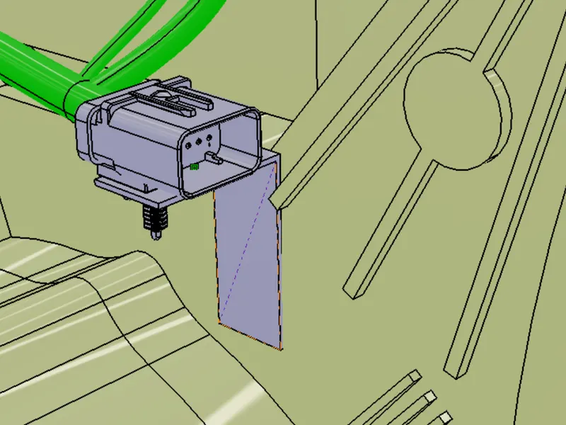
- Basically the routing was started from the right side of the engine.
- Two P-clamps (orange) and two fir-tree clips(pink) were placed as shown in order to guide and keep the bundle intact.
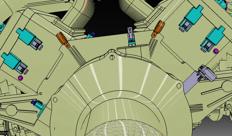
- The main branch routing was done from the interconnection connector to the 1st P-clamp and then to the 2nd and then to the connector connected with the speed sensor.
- Then the sub-branches were added which are connected to other connectors and fir-tree clips.
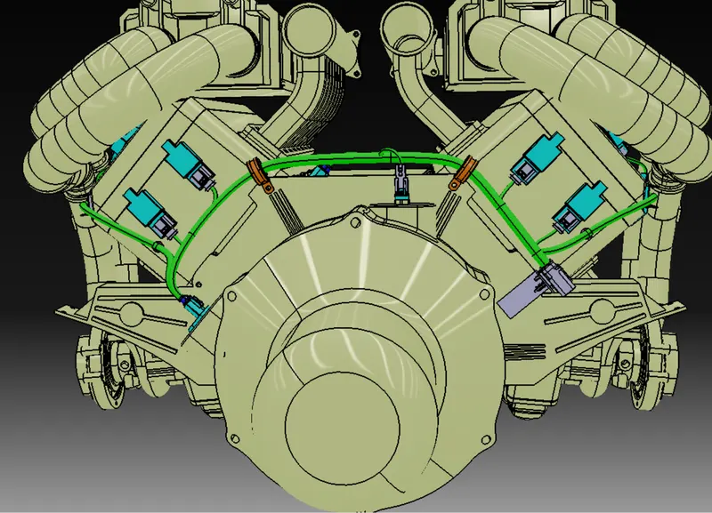
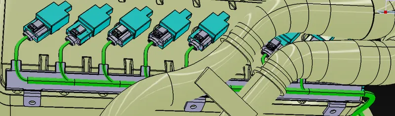
- In order to connect the injectors, guiding channels have been used. These were placed on the required position using Manipulate command and Compass
- The guiding channels were also electrically defined using the Define Equipment command and the bundle entry points were defined using Defien Bundle Connection Point.
Checking Bundle Continuity:
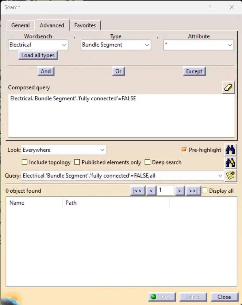
- Multi-branchable was selected then Edit>Search>Advanced>
Workbench-Electrical>Type- Bundle Segment>Attribute-Fully Connected - Now by selecting False, it showed 0 objects found, which means every bundle segment is fully connected.
Applying the protection:
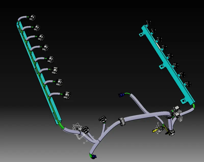
- Cot Tubes were provided to the bundles depending on the diameter.
- End extremity clearance was taken as 30mm from the connector end.
- Cot tubes were not applied to the bundles which are inside the channel.
- The bundles connected to the injectors were given end extremity clearance of 15mm from the connector end.
Harness Flattening
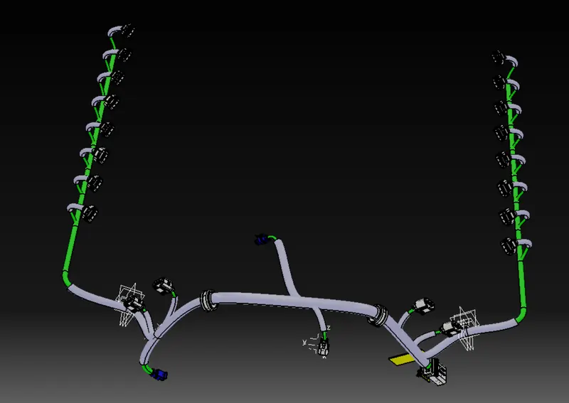
- Flattening parameters: 'Single line' for bundle segment and 'Double' line for protective covering.
- Fattening file was saved in the same folder where other harness assembly files of were saved.
- The Harness assembly was imported into the Electrical Harness Flattening Workbench.
- The assembly flattened the file along the face of the interconnection connector
- After applying the flattening, some required changes were done using the rotate command. And also changes were made inside the Mechanical Assembly Workbench.
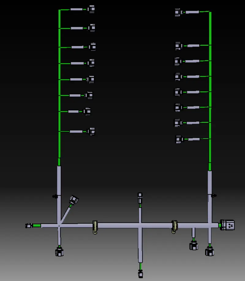
Drawing Sheet:
- The Harness Flattening file was imported into the Drawing with sheet parameters: A0 ISO landscape
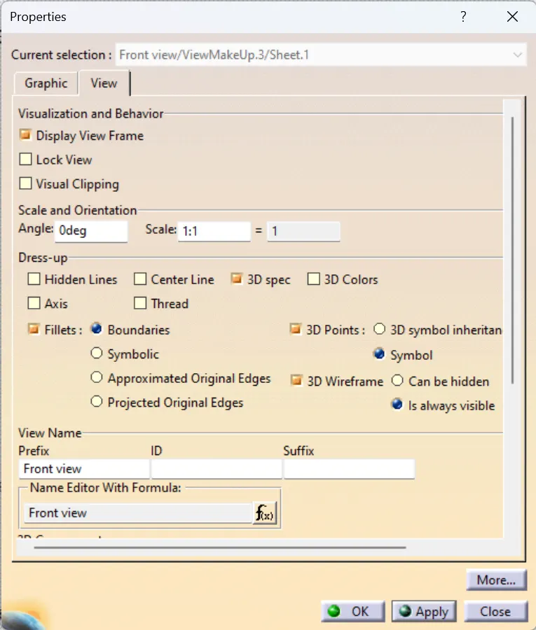
- And the following properties were checked:
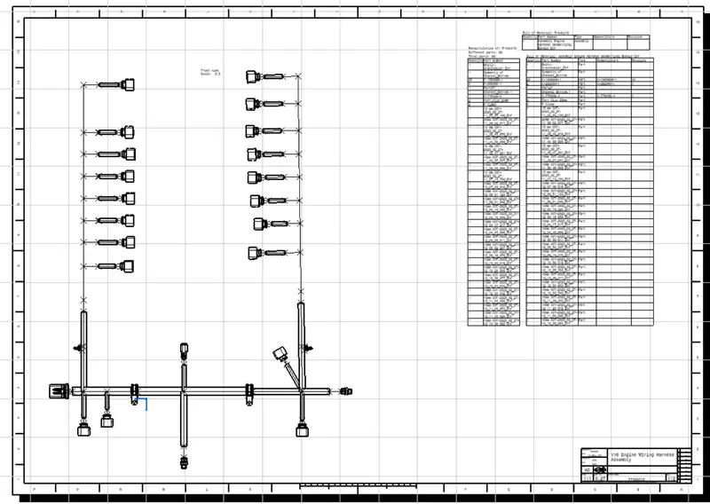
- Bill of materials and Title Box were provided
Assumptions:
- Clips/clamps were provided as per requirement.
- it was made sure that there is no fouling case/ interference of two similar or dissimilar components while designing the wire harness.
- Additional clips/clamps may be used to avoid fouling.
- Routing over the bolt and bolted joints were avoided to avoid harness puncture.
- Routing on sharp edges was avoided or else protection over the harness was provided.
- Additional slack was given wherever needed(5-10% )
- The harness was kept away from heat generation components. Protection was provided according to the surrounding temperature.
- Avoid direct support for harnesses on fuel lines routed in the engine.
- It is not recommended to mount anything with the manifold mounting bolts
- Branch length was greater than 50mm.
- Minimum distance between two branch points was at least 50mm.
- Minimum distance between clip and branch was at least 25mm.
- Too many sheet metal brackets on the engine were avoided. (Try to use available threaded bosses on the engine or demand for it.)
- The wiring harness should be easy to assemble and easy to access.
- While using dummy connectors, ensure that whatever positions we are defining are practical. Bundle diameters and other placements can be defined properly for the wire harness routing.
- If the packaging area is too tight and there are many packaging constraints, a harness channel can be used to route and protect the wire harness effectively. Hence the available area near the injectors is very less hence we need to create a channel to manage the wiring harness. This is done on both sides of the engine.
The Electrical Wiring Harness Assembly of the V16 engine was created along with a flattened view and a 2d drawing sheet of the same, all the components have been electrically defined and have been added to a catalog.