Project 1
Aim and Introduction:
To apply the dead loads, IRS live loads, Earthpressure loads, wind loads and seismic loads for the given bridge structure at Ahmedabad metro rail project.
- Dead loads :
The dead loads are self-weight of the structural elements like a beam, deck slab, pier, wall, etc.
- IRS live loads :
The IRS live loading classified as
- Metro rail loading,
- Broad gauge loading,
- Electric train loading,
- Guage A and Guage B loading.
Metro rail loading :
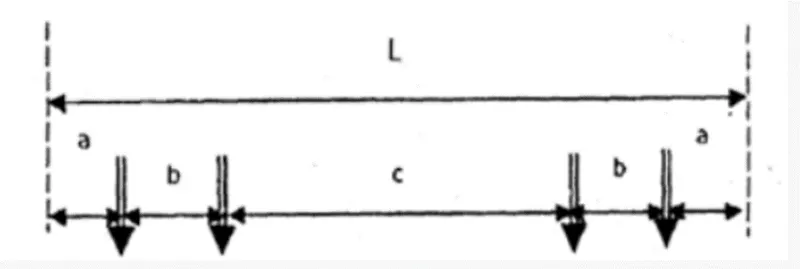
Fig. 1
- Axle load will be maximum of 17 tons, max. number of cars are 6 nos,
The wheel configuration :
Length : a = 2150mm
b = 2200mm
c = 12400mm.
over all length of car is 21100mm= 21.1m
- Earth pressure loads :
1. Active Earth pressure:
Active Earth Pressure states that the wall moves away from the backfill.
2. Passive Earth pressure.
-
Passive Earth pressure states that the wall moves towards the backfill.
-
3. Earth pressure at Rest.
The vertical structure at rest and there will not be any displacement.
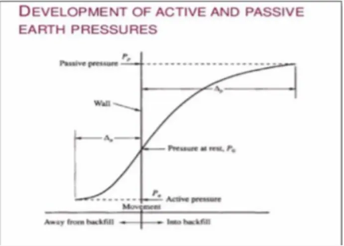
Fig. 2
- Wind Loads:
The wind speed is classified in to 5 different zones based on their location '
1. 33 m/s
2. 33-39 m/s
3. 39 - 44 m/s
4. 44 - 47 m/s
5. over 50 m/s
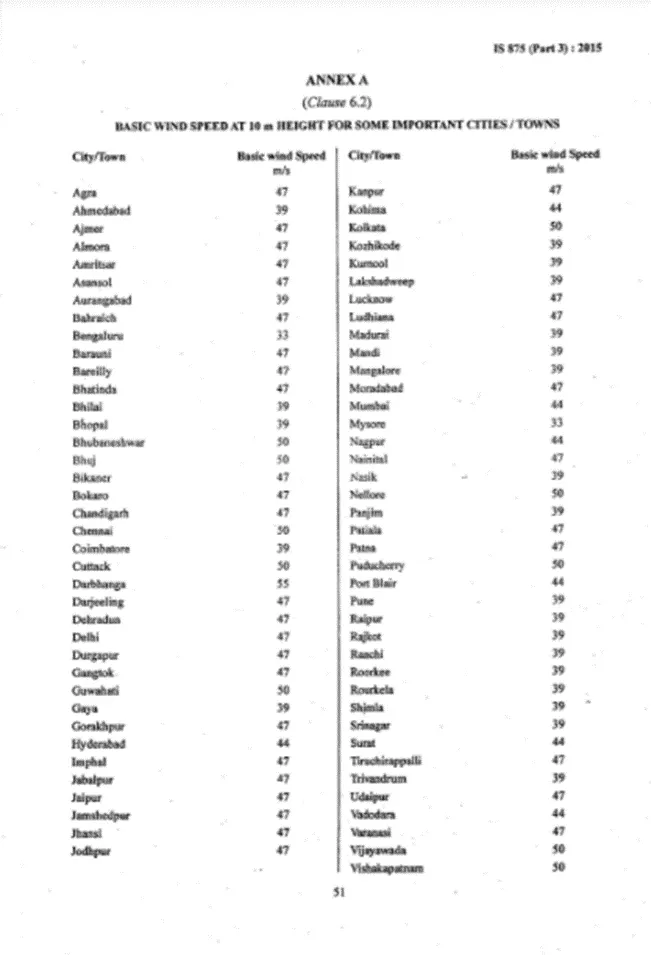
Fig. 3
Design wind speed can be calculated using formula Vz = Vb * k1* k2* k3* k4
wind pressure : Pz = 0.6 * (Vz)^2
where, Vz= design wind speed, Vb= basic wind speed, K= Factor.
- Since the metro station is underground, so there will be negligible effect of wind on the strucure.
- Seismic Loads:
Seismic loads are classified based on 4 types of zones(IS 1893 part 3)
1. zone 2(low)
2. zone 3(moderate)
3. zone 4(severe)
4. zone 5(very severe)
Calculating Earth pressure loads on the structure(Retaining wall).
K= Ka*Y*H
Y=unit weight of soil= 18KN/m^3
Ka= 0.35, H= 2100+5400+5100=12600mm= 12.6m
K= 0.35*18*12.6= 79.38 KN/m^2
The load of 79.38KN/m^2 will be acting on the retaining wall.
Procedure:
- In this project we are going to apply the dead loads, live loads, earth pressure loads, wind loads, and seismic loads and analyse in the staad pro.
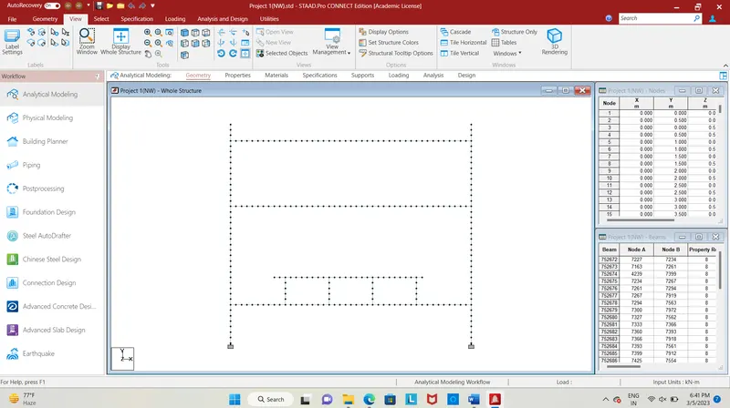
Fig. 4
- The fig shows the front view of Ahmedabad metro rail structure, having three levels as the floor level, concourse level and platform level.
- Since the structure is given, we apply loading to the structure.
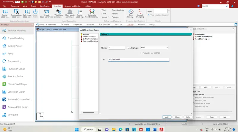
Fig. 5
- First, we need to give a self-weight loading for the structure, click on load case details add a new load case, add self weight and close the tab.
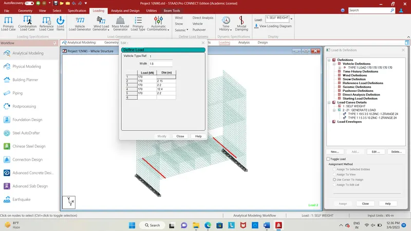
Fig. 6
- After adding self weight load we need to give IRS METRO RAIL loading to the structure, the metro rail loading is need to be added at platform level.
- Click on the load case details click add, enter as metro rail loading.
- In the load and distance column enter the values specified for metro rail loading which has constant loading of 170kN and distance varies accordingly with axle.
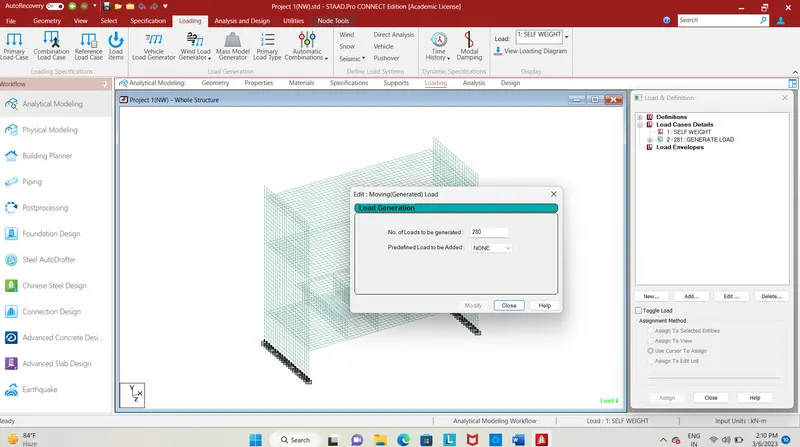
Fig. 7
- Load generation = (length of vehicle + span ) / increment of loads = (21+260)= 281
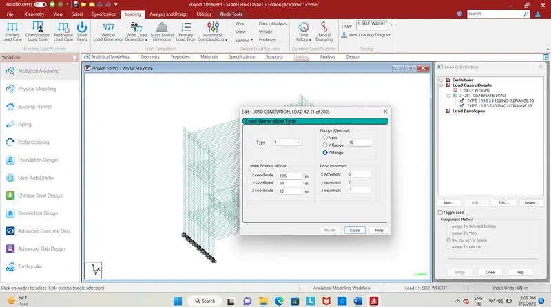
Fig. 8
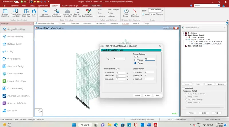
Fig. 9
- After specifying the load and distance we need to enter the x,y,z co-ordinates to specify the load position.
- We apply the load on platform level at the rectangular beam, having coordinates (1.5,3.5,10) and (19.5,3.5,10) with increment in Z-direction(-1).
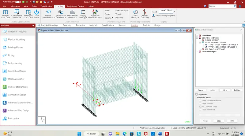
Fig. 10
- The fig shows the IRS metro rail loading to the structure.
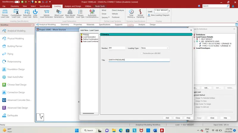
Fig. 11
- Next loading is Earth pressure loading, add a new load case detail, click on that and give title as earth pressure click add and close it.
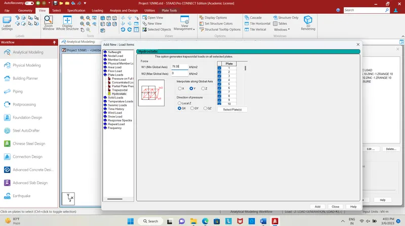
Fig. 12
- The earth pressure loads of 79.38 KN/m^2 max at bottom and minimum(0) at bottom is applied to the strucure in Gx direction and interpolating along Y-axis. by selecting plates load is applied.
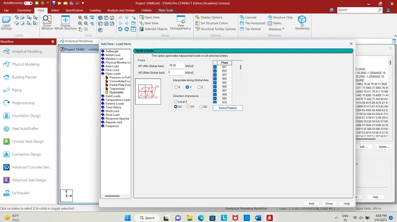
Fig. 13
- Similarly earth pressure of -79.38 KN/m^2 is applied to the plates structure on right side interpolating along Y-axis, in the GX direction.
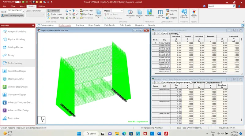
Fig. 14
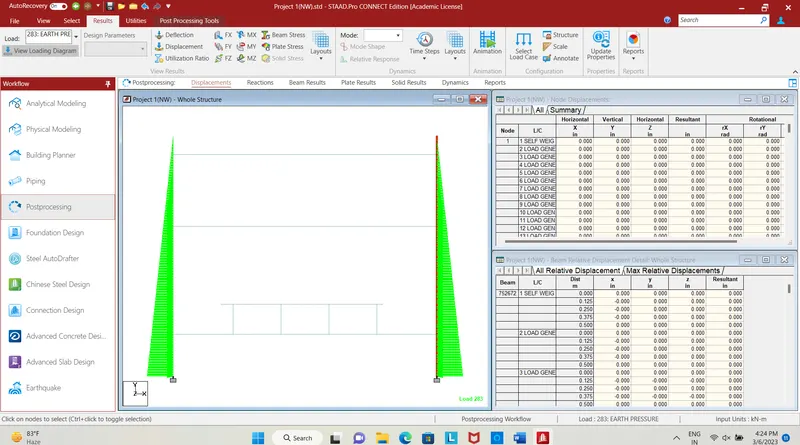
Fig. 15
- The above image shows the earth pressure loads in x direction where the intensity will be more at bottom and will be less while coming up.
- The above two images shows that load in - x direction one is front view and nexrt one is display whole structure, while clicking on hydrostatic loading the staad will itself calculate and assign loads accordingly with height , so the load intensity varies with increase in height.
- Now, wind load is applied.
- Since the metro station is under ground, so there will be negligible effect of wind load. So we neglect the effect of wind load.
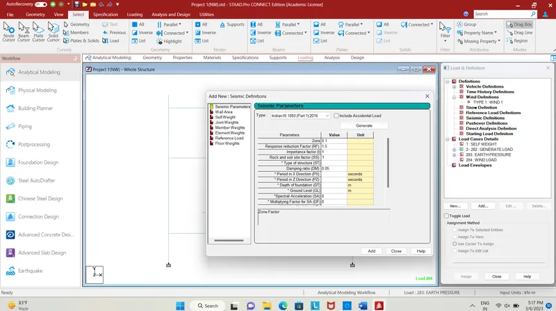
Fig. 16
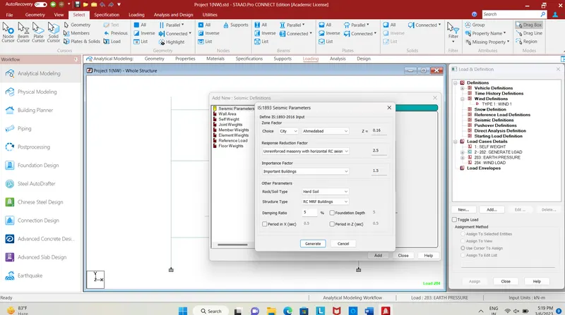
Fig. 17
- Next we need define seismic load to the structure, click on definitions adds seismic definition select the type as Indain 1893 2016 part 1, then click generate.
- a new tab will open where you can slelct the city Ahmedabad, and then select it as important building so importance value will be get selected, then click add.
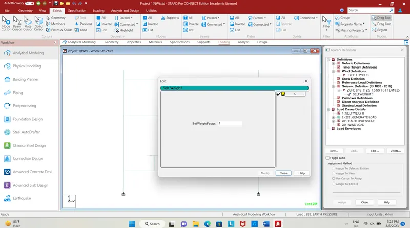
Fig. 18
- click on the self weight and add it to the seismic definitions.
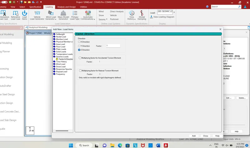
Fig. 19
- After that add new case details, click add select seismic loads, click on factor direction x to generate seismic loads.
- After loading, click on analysis and design, select run analysis command, after analysis enter into post-processing mode.
RESULT:
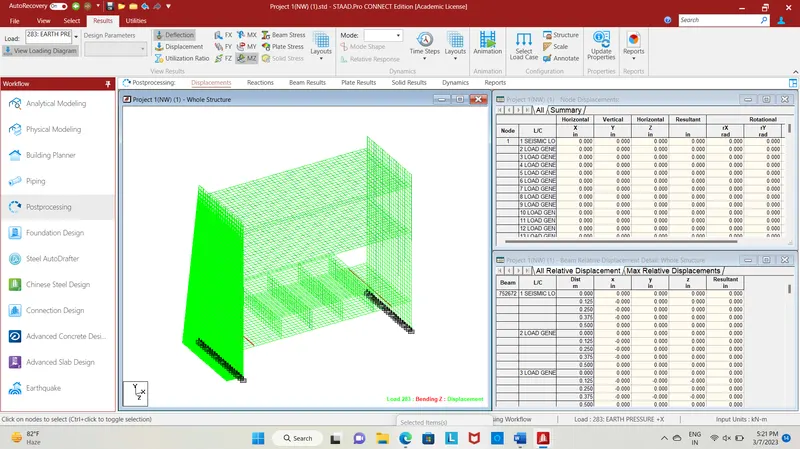
Fig. 20
- After entering postprocessing mode, the fig. shows the earth pressure loads and moment MZ, the moment in the rectangular beam.
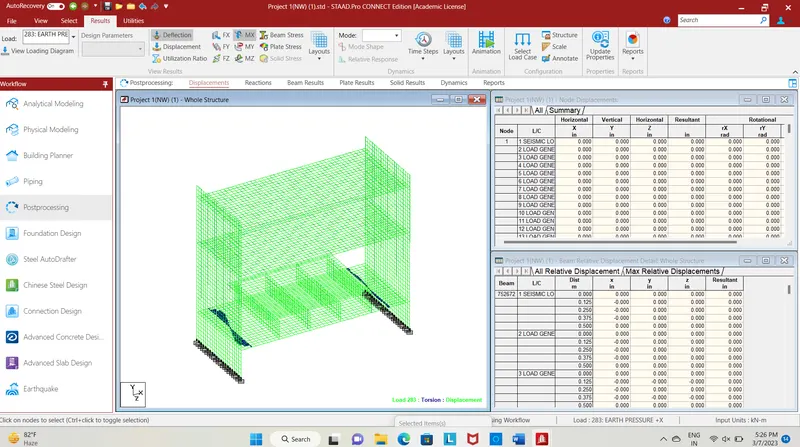
Fig. 21
- The fig shows the bending moment Mx in rectngular beam due to earth pressure.
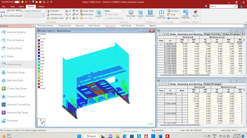
Fig. 22
- The fig shows the plate stress due to metro rail load in SY(local).
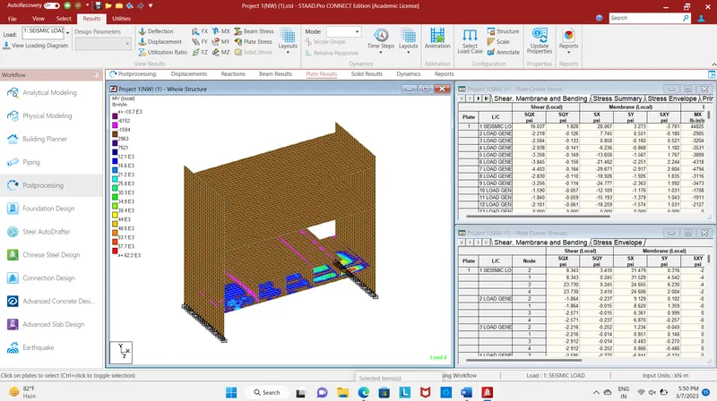
Fig. 23
- The fig shows the contour image of plate stress due to Mx.
- Hence the dead load, live load, earth pressure, seismic loading has been applied and their load analysis has been done.