Project 1
Objective:
- 1. Design a battery pack for a car roughly 150 Kw with 120 V. Use 3500 mAh 3.6V nominal NMC chemistry cell.
- a. Design the battery pack configuration.
- b. Draw the BMS topology for this battery pack.
- 2. Build a 3S2P battery pack configuration with generic battery block using Matlab/Simulink.
Theory:
1. Design a battery pack for a car roughly 150 Kw with 120 V. Use 3500 mAh 3.6V nominal NMC chemistry cell.
a. Design the battery pack configuration.
b. Draw the BMS topology for this battery pack.
Requirements:
Design a battery pack for a car roughly 150 Kw with 120 V. Use 3500 mAh 3.6V nominal NMC chemistry cell.
Car power requirement =150Kw with 120 V
So Power = Current capacity * Voltage supply
Power = 150 Kw = 150000 w
Voltage = 120 V from this we can calculate No. Of cells in series.
Current Capacity from this we can calculate No. Of cells in parallel.
Current capacity of battery pack = Power / Voltage
= 150000 /120
= 1250 Ah
Current capacity of battery pack = 1250 Ah
Construction of battery pack:
To construct a battery pack initially we have the voltage requirement of the overall load of vehicle 120 V and 1250 Ah.
Then the battery modules should be created in such a way that the overall voltage is matched with the load requirement voltage.
The modules can be created in series/parallel connections of individual cells.Then every modules should be connected in series/parallel to construct final battery pack.
In series connection-Voltage added and Current remains same.
In Parallel connection-Voltage remains same and Current gets added.
Basically, the value of the volume of the cell is used to find out the total volume of the battery pack.
Data given for cell
Use 3500 mAh 3.6V nominal NMC chemistry cell.
Cell Capacity (Ah)=3500mAh = 3500/1000 Ah =3.5 Ah
Cell Voltage (V)= 3.6V
- Single Cell Energy (Wh)
= Cell Capacity (Ah) x Cell Voltage (V)
= 3.5 x 3.6
= 12.6 Wh
For 150KWh battery pack we need approximately
(150000/12.6=11904.76 cells ≈ 11905 Cells).
We have to create a single module to produce 120 V for our load requirement.
So to obtain 120 V output ,cells are connected in series where voltage become added and current remains same.
Nominal Voltage of Pack = Single Cell Voltage * No. Of Cells in series
120=3.6 * No. Of Cells in series
No. Of Cells in series = 120/3.6 = 33.333 ≈ 34 Cells in Series.
Thus single module gives as 122.4V from 34 cells but energy of one module is not enough to run the vehicle as motor power rating is higher.The energy generated from
single module is 122.4 * 3.5 = 428.4 Wh.
Now we have to find how many similar modules should be connected in parallel to achieve 150KWh battery pack.
Power = Pack Nominal Voltage * Nominal Current of Pack
150 KWh = 120 * Nominal Current of Pack
150000 Wh =120 * Nominal Current of Pack
Nominal Current of Pack = 150000/120 = 1250 Ah
Nominal Current of Pack = Single Cell Nominal Current * No. Of Cells in Parallel
No. Of Cells in Parallel = Nominal Current of Pack/Single Cell Nominal Current
No. Of Cells in Parallel=1250/3.5 = 357.14 ≈ 358 cells
Thus the battery model is said to be 34S358P configuration(34 series and 358 parallel connections),which gives us (34*358 =12172 cells).From this we have created overall capacity of battery pack as
(12172 * 12.6Wh=153367.2 Wh) which is slightly higher than 150KWh.
The overall Capacity(Ah) of battery pack is given as (3.5Ah * 358 = 1253Ah).
Which means it provided 1253 Ah of current continuously for one hour to full discharge.
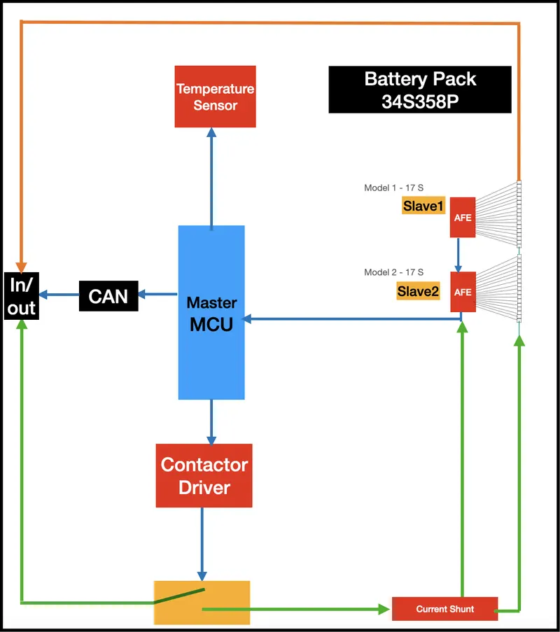
- Master Slave Topology type BMS for an EV battery of 122.4 V and 1253 Ah.
- This BMS can be used in battery packs which consist of more than 18 No. Of cells in series. We have calculated 34 cells in series. So 34*3.6 =122.4 V
- This type of BMS used in four wheelers and Large energy storage battery pack system.
- Battery Pack requirement is 2 Slave BMS which has 17 cells in series in each pack and connected in series so 34 cells in series.
- To distribute 358 cells in parallel as per BMS requirement so capacity of battery pack = 358 * 3.5 = 1253 Ah
- Finally battery pack configuration become 34S358P
- Master Slave Topology BMS architecture type for an EV battery of 122.4 V and 1253 Ah.
Master-Slave: This architecture comprises of the Master and Slave BMS units. The slave unit monitors, balances and controls a group of battery cells within the battery module. It communicates with the master unit through a communication interface.The Master unit is responsible for state estimation, control of Power Distribution Unit (PDU) and external communication. A master-slave BMS is similar to a modular system, in the sense that it uses multiple identical modules (the slaves), each measuring the voltage of a few cells.
- Build a 3S2P battery pack configuration with generic battery block using Matlab/Simulink.
3S2P Battery Pack Configuration Using Simulink Model:
The objective of this article is to connect batteries in 3S2P configuration in Matlab/Simulink. That is 3 cells should be connected in series and 2 cells should be connected in parallel.
Total number of cells in battery pack = No. Of cells in series * No. Of cells in parallel
= 3*2 = 6 cells
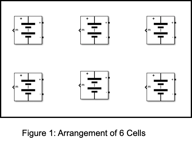
Step : 1 Arrangement of 6 cells
The Figure 1 shows the arrangement of 6 cells. We have to place total number of cells in battery .
Step : 2 Parallel connection
The Figure 2 shows the batteries connected in parallel. For parallel connection, batteries are connected from terminals to same terminals of other batteries that is positive terminal(+) of one battery is connected with positive (+) terminal of other battery and negative terminal (-) of one battery with negative terminal (-) of other battery.
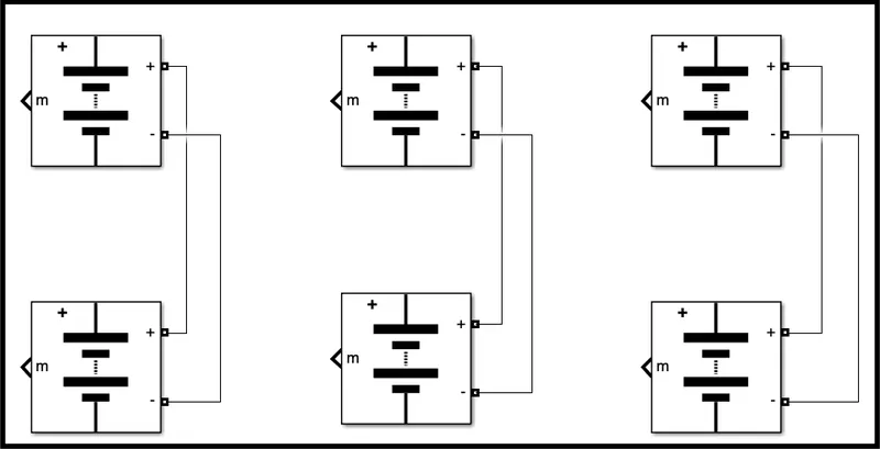
Figure 2: Battery connected in parallel connection
Step : 3 Series connection
The Figure 3 shows the batteries connected in series and parallel combination. Batteries are connected from terminals to terminal in a way that the positive terminal(+) of one battery is connected with negative (-) terminal of other battery and negative terminal (-) of one battery is connected with the positive terminal (+) of the other battery.
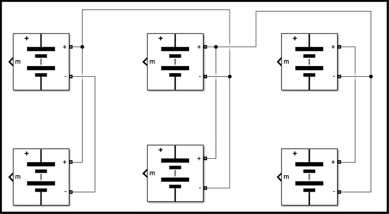
Figure 3: Battery connected in Series and Parallel combination
Model Explanation :
The Figure 4 shows the 3S2P Battery pack simulink model. The voltage measurement block is connected across the battery pack to measure the battery pack voltage. The scope output used for the battery pack consists of SOC (State Of Charge), Current and voltage. The controlled current signal is given as the load to the battery pack. The constant block is determined with battery capacity and it is given to the controlled current block.
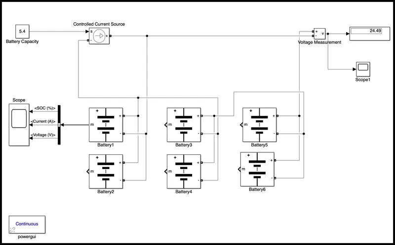
Figure 4:3S2P Battery Pack Simulink Model
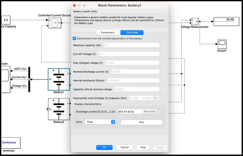
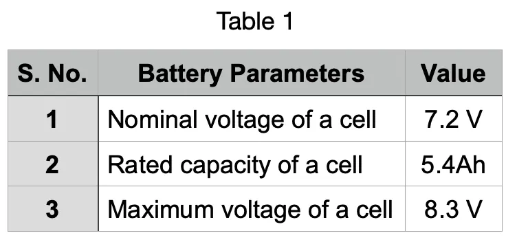
The parameter given inside the battery is given below,
Nominal voltage of the battery pack = No. Of cells in series * nominal voltage of a cell
= 3*7.2 V = 21.6 V
Rated capacity of the battery pack = No. Of cell in parallel * rated capacity voltage of cell
= 2 * 5.4 Ah = 10.8 Ah
The model is for an 21.6 V / 10.8 Ah battery.
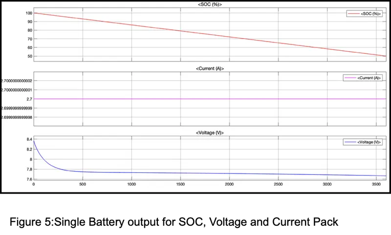
The figure 5 shows the single battery output for SOC, voltage and current.
- Plot 1: The SOC (State Of Charge) is started to reduce from 100% to 50 % corresponding to the load given.
- Plot 2: The current signal is determined by the load and the decrease in current is due to regenerative braking.
- Plot 3: The voltage is around 8.3807 V. The increasing and decreasing voltage is with respect to the regenerative braking.
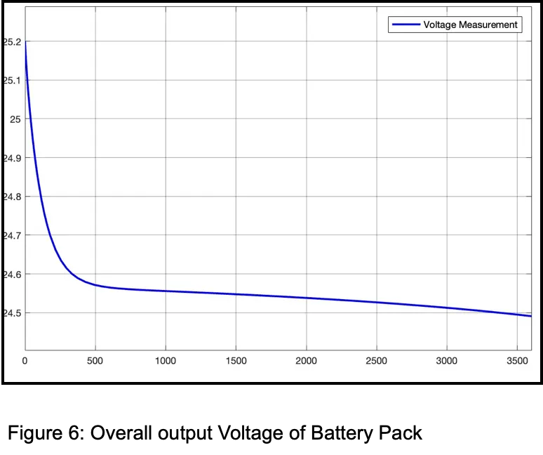
The figure 6 shows the overall output voltage of the battery pack. The calculation for the overall output voltage of the battery pack is given below.
Overall voltage of the battery pack = maximum voltage of the battery * No. Of cells in series
= 8.3807 V * 3 = 25.1421 V