Project 1
Aim and introduction – Ultimate aim is to construct a feasible, sustainable, cost-effective underpass by analyzing and designing raft foundation considering different loads, such as dead load (self weight), superimposed dead load, earth pressure, live load surcharge, breaking load, temperature and live load etc.
In this project Economic Span Arrangemrnt has been carried out with hydraulic and traffic survey data.
Soil density and safe bearing capacity evaluted from soil investigation report.
FRL is also fixed and a fill of 1.5m is adopted.
Materials and it's quality / grade is also finalised.
The design of Raft foundation with other various components of the bridge, in general are based on provisions of IRC. The list of IRC Codes (latest revisions) given below will serve as a guide for the design of structures.
IRC : 5 - 2015 Standard Specifications and Code of practice for Road Bridges, Section I - General Features of Design
IRC : 6 - 2014 Standard Specifications and code of Practice for Road Bridges, Section II - Loads and Stresses
IRC : 112 - 2011 Code of Practice for Concrete Road Bridges
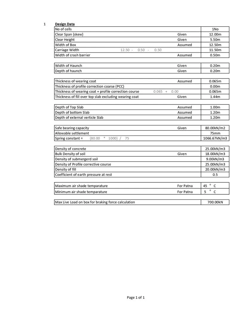
Step 1) Creating a model in STAAD with given dimensions and design data
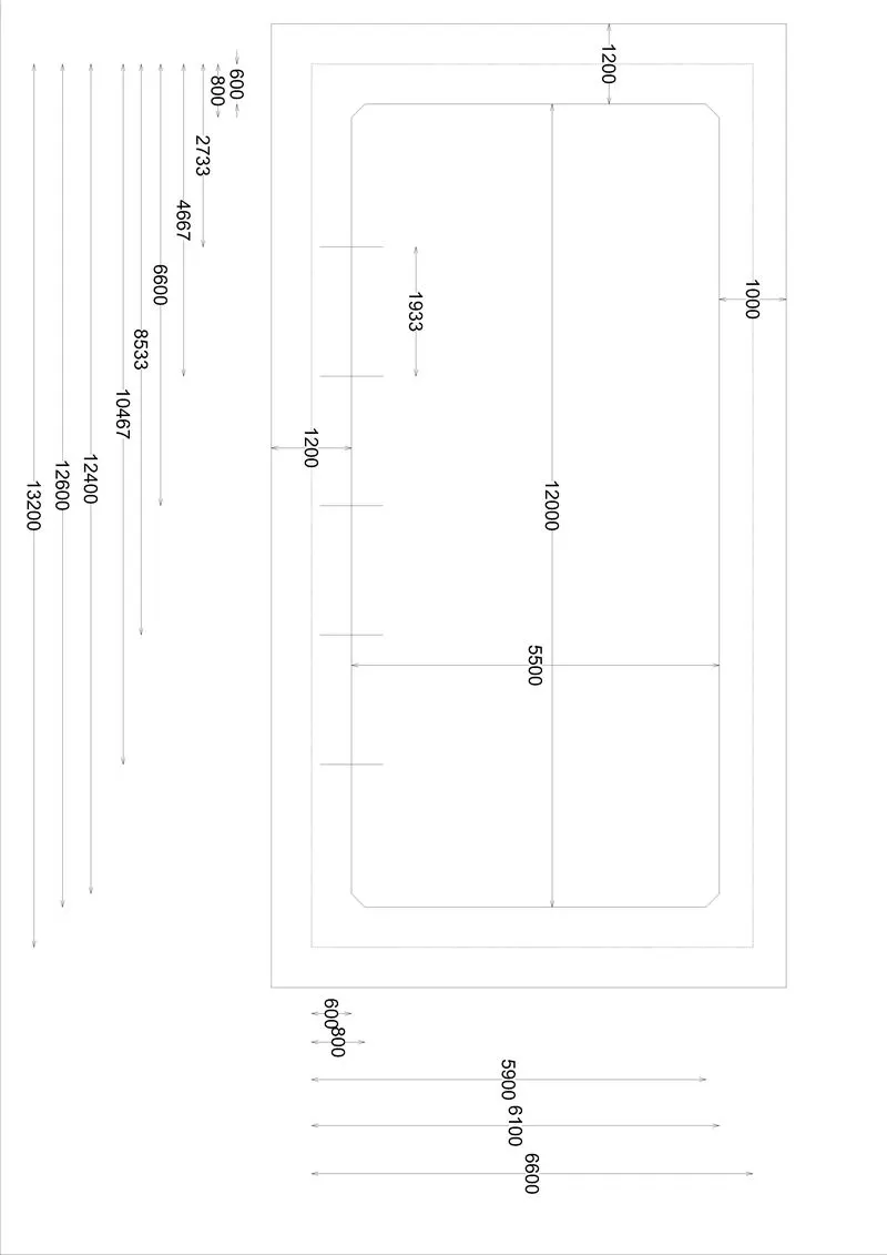
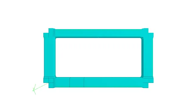
The bridge under pass is modeled as a frame structure taking the centre line dimension.
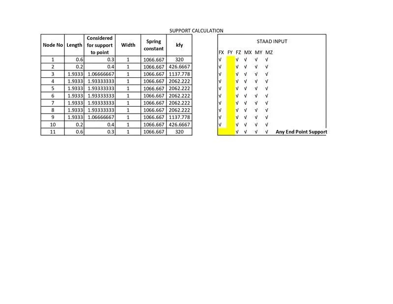
Spring supports for different point finalised, and assigned.
Q-1 Calculate the loads to be applied on the box as per IRC 6
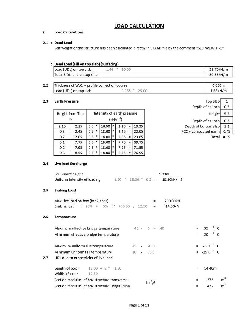
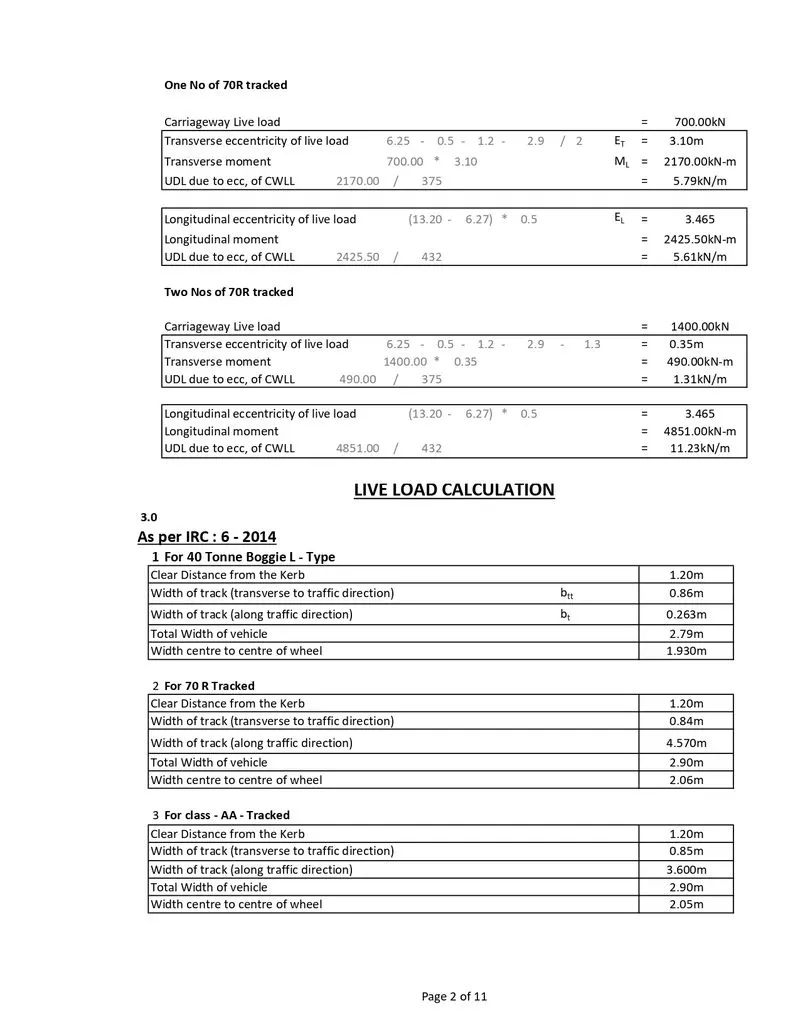
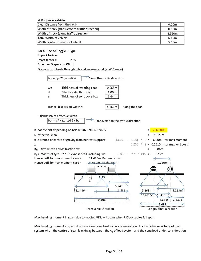
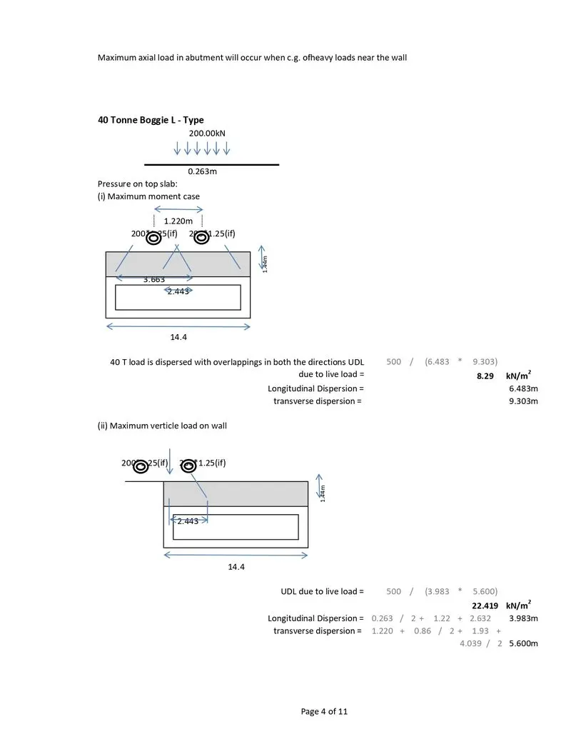
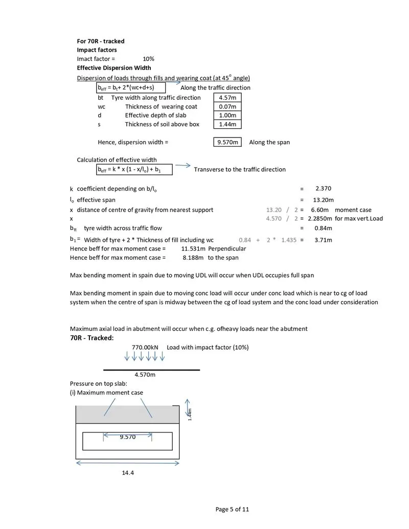
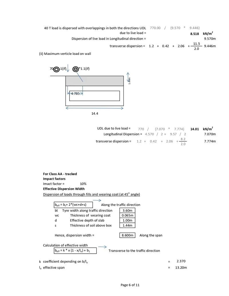
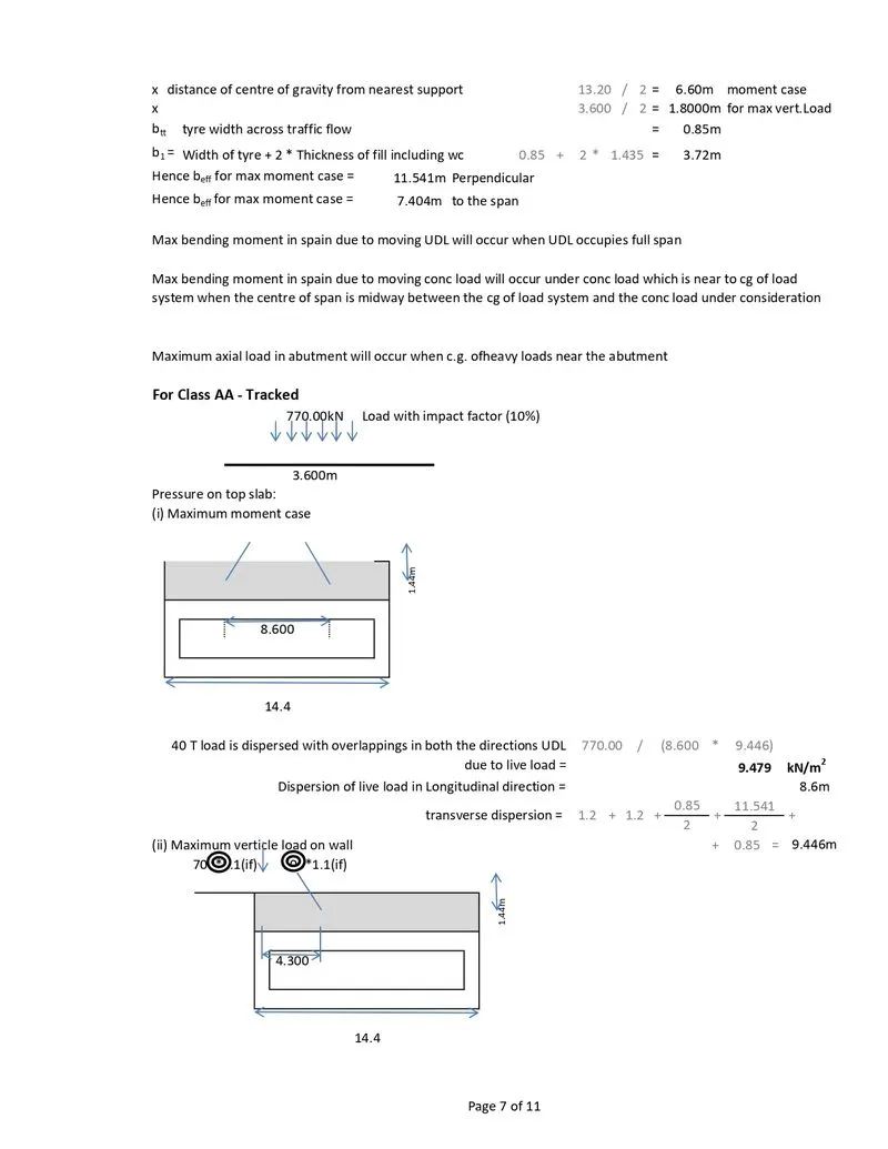
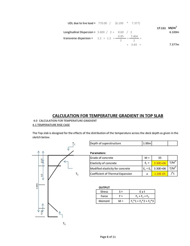
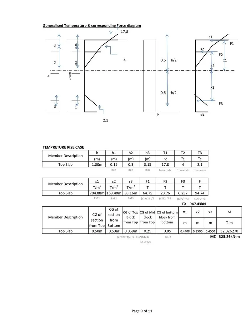
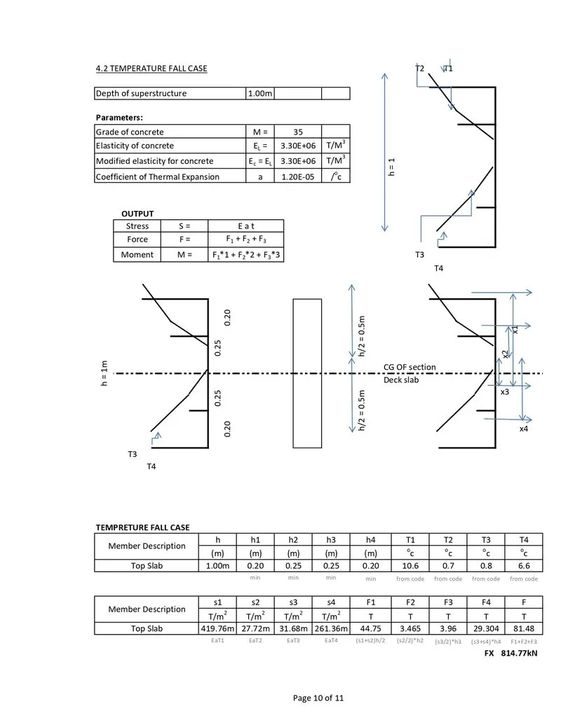
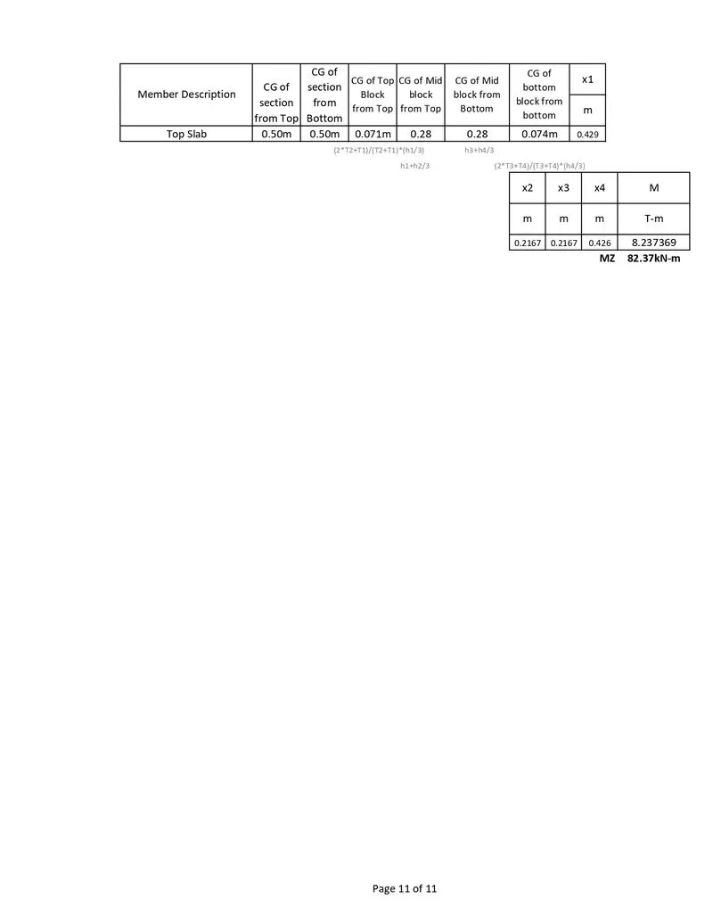
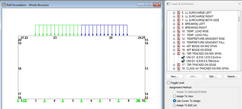
Q-2 Live load analysis and effective width calculation for 70 r and class A done and assigned to respective beams.
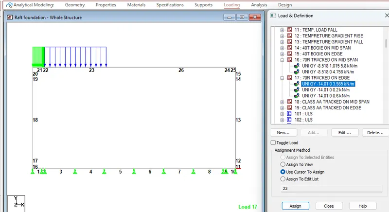
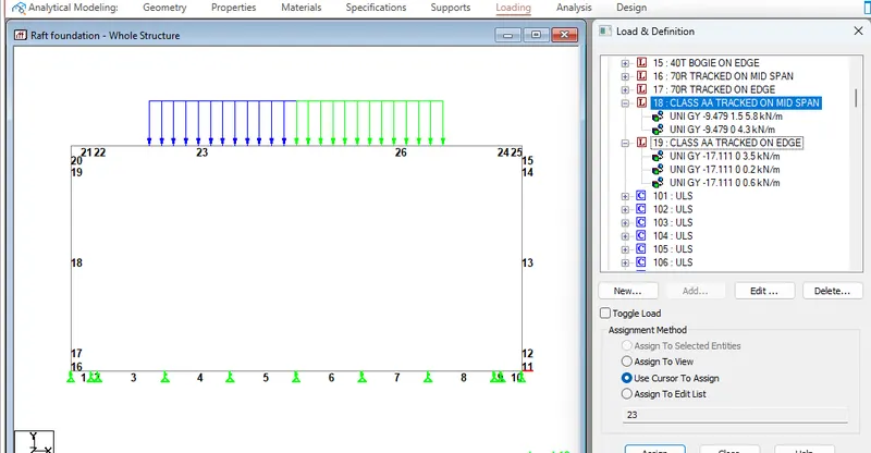
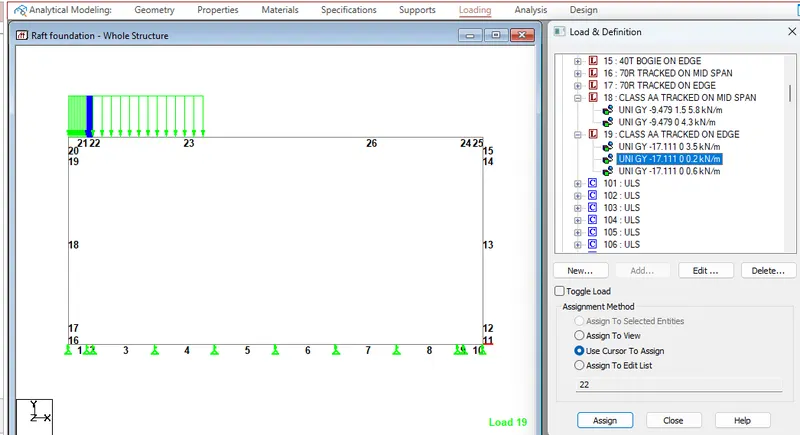
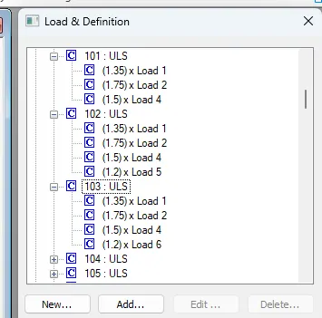
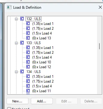
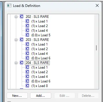
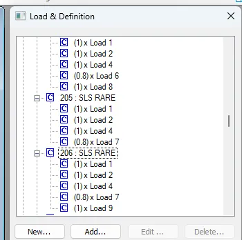
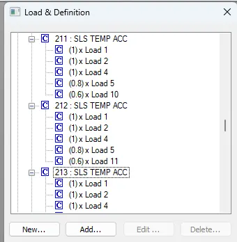
Q-3 Make Load combinations as per IRC 6 for ULS,SLS rare and quasi.
Load combination ULS
Load combination SLS RARE
Load combination SLS RARE Tempreture accompanying
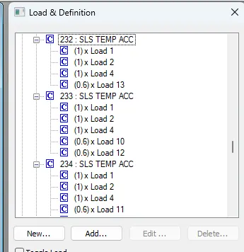 Load combination SLS RARE Tempreture leading
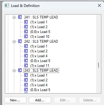
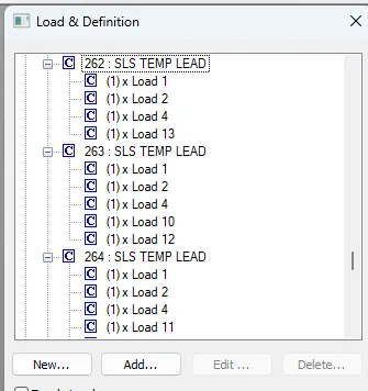
LOAD COMBINATION SLS QUASI PERMANENT
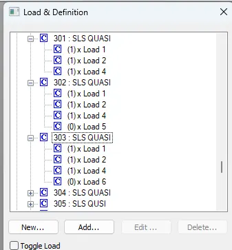
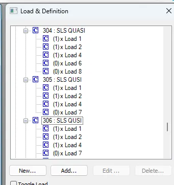
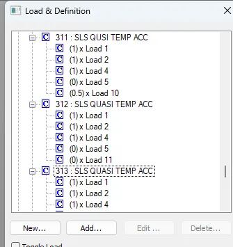
SLS QUASI PERMANENT TEMPRETURE ACCOMANYING
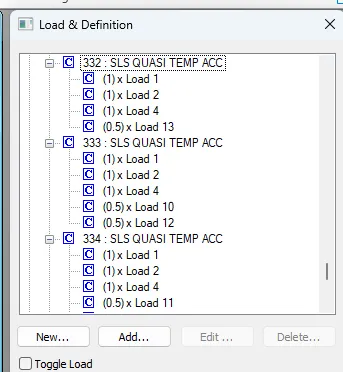
SLS QUASI PERMANENT TEMPRETURE LEADING
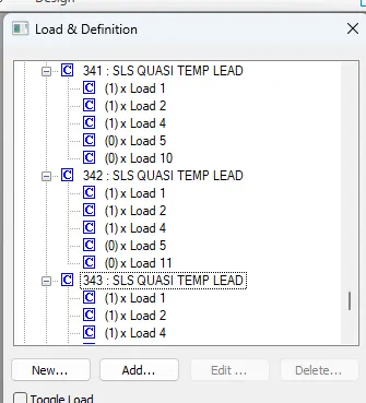
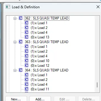
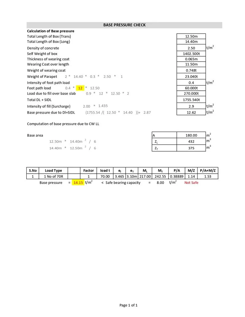
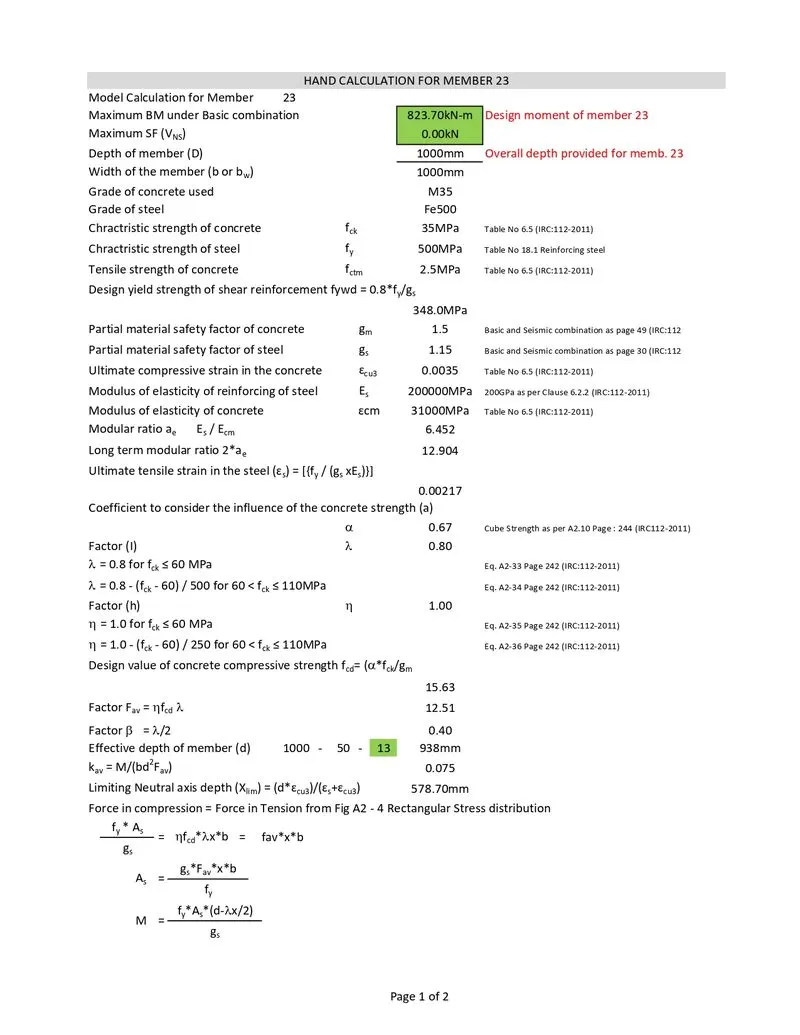
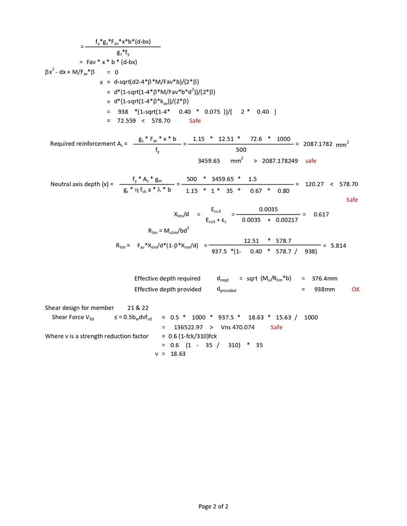
Q-4 Do checks for ULS,SLS rare and quasi and present a hand calculation.
Checks done based on following force summary obtained from STAAD PRO post processing results after analysing.
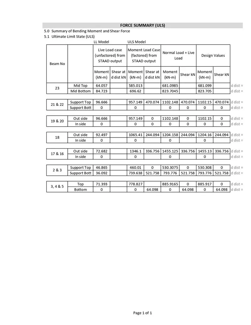
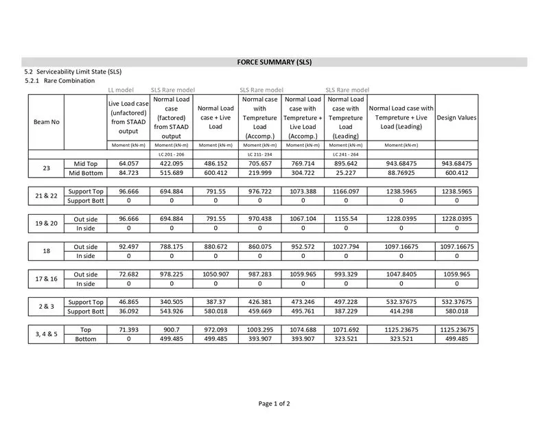
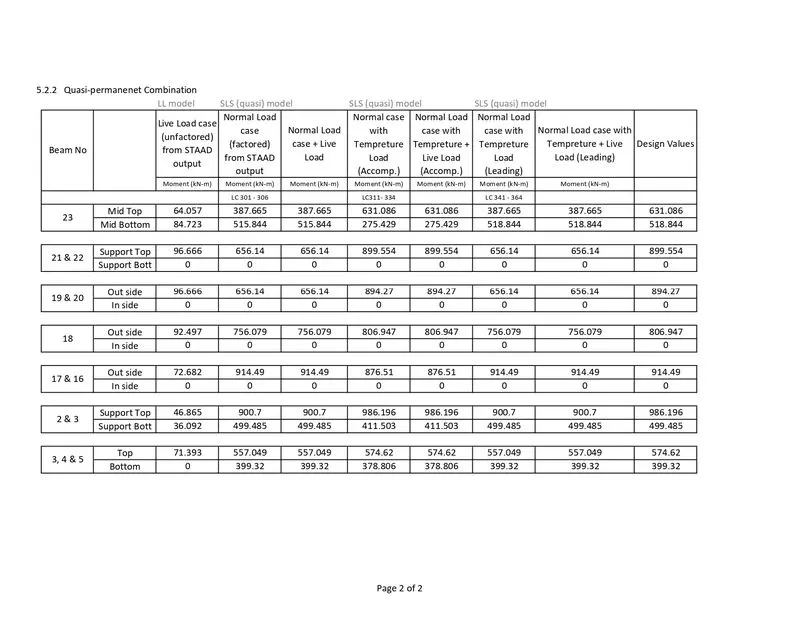
Checks
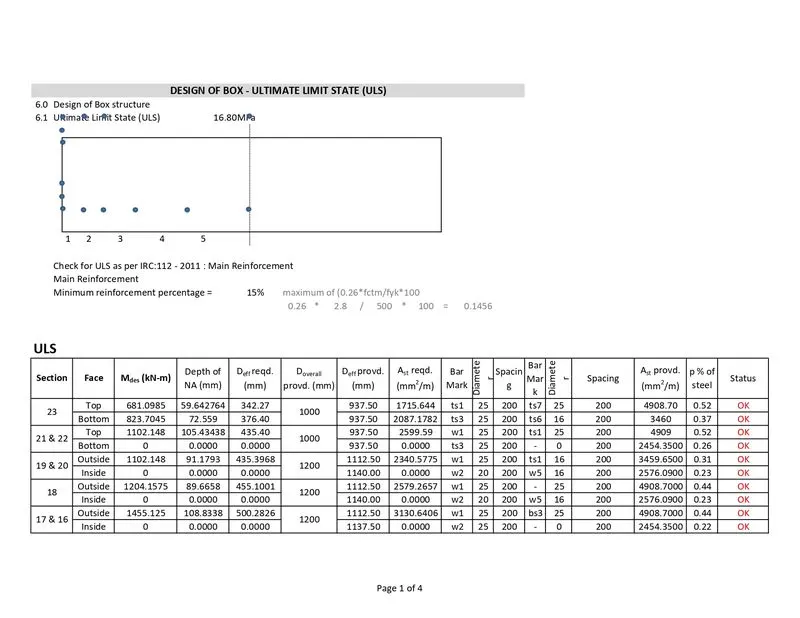
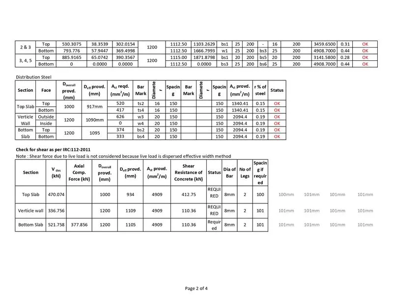
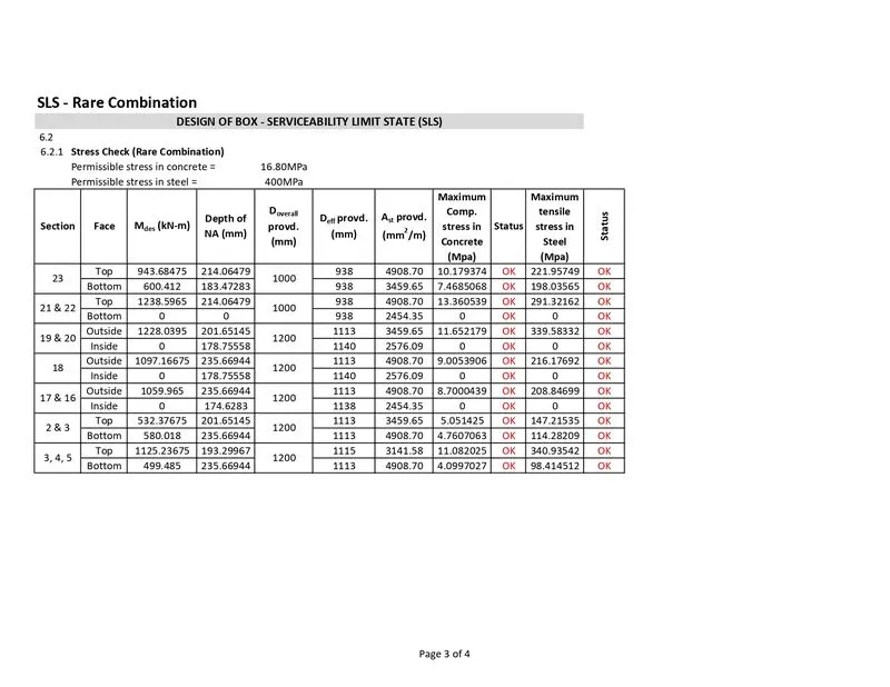
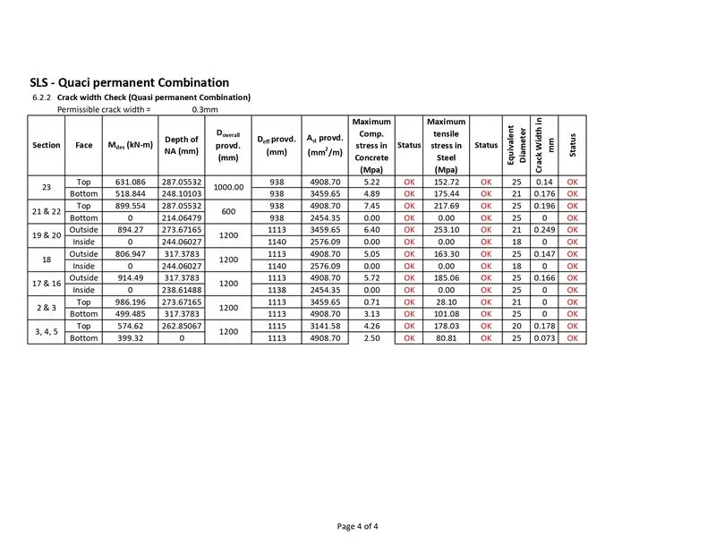
Hand calculation
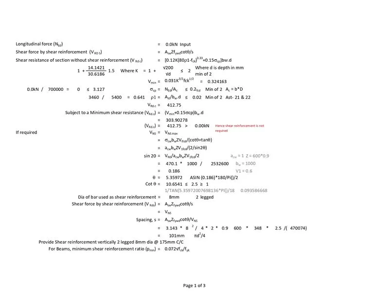
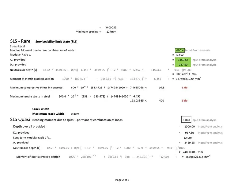
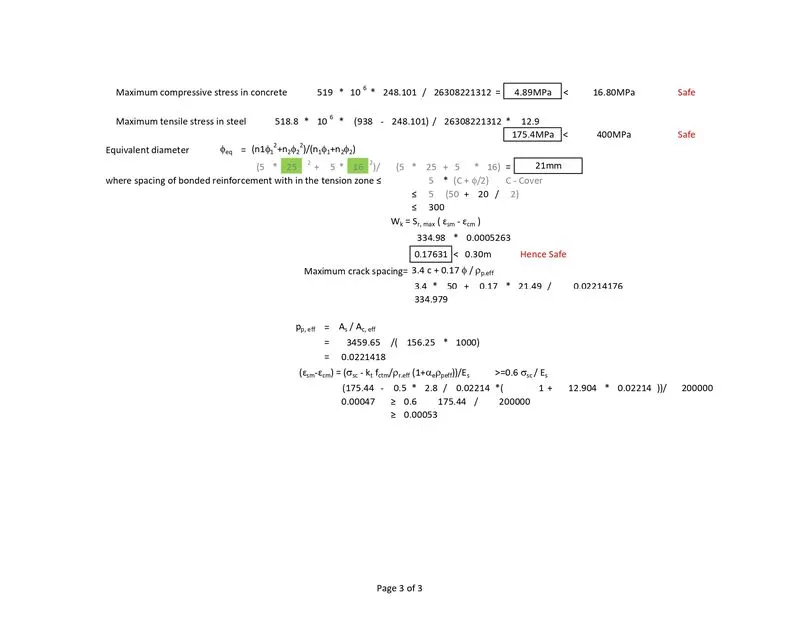
Excel sheet attached
Q-5Also calculate the anchorage length of the bars and minimise the bars wherever you can.
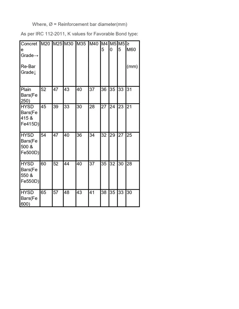
Fe 500 is used so for 25mm dia it will be 25*36 = 900mm
20mm dia it will be 20*36 = 720mm
Q-6Draw rebars to the scale and therefore calculate the kg/cumec of the base slab.
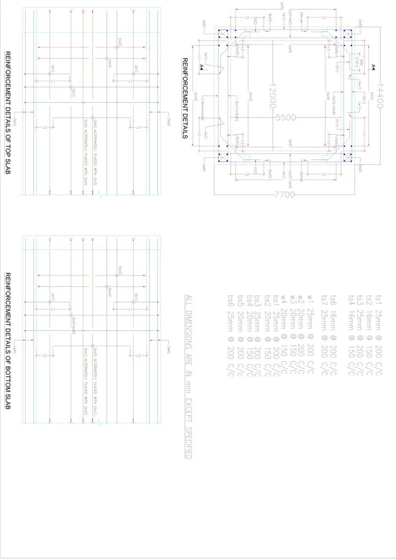
Q calculate the kg/cumec of the base slab.
| 8/14.1 (D)(P) | Plain/Reinforced cement concrete in sub-structure complete as per drawing and technical specifications | |||||||
| (b) RCC Grade M- 35 using batching plant, transit mixer & concrete pump. For height upto 5m. | cum | |||||||
| RCC Box Cell (12.0 m span) | ||||||||
| Bottom | 1 | 12.50 | 14.40 | 1.200 | 216.000 | 216.00 | ||
| Haunch at Bottom Slab | 2 | 12.50 | 0.5x0.2 | 0.200 | 0.500 | 0.50 | ||
| 216.50 |
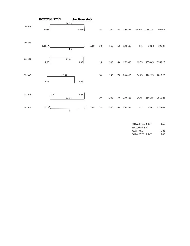
16600.6kg / 216.5 cumec = 76.67kg/cumec