Project 1
1. Design a battery pack for a car roughly 150 Kw with 120 V. Use 3500 mAh 3.6V nominal NMC chemistry cell.
a. Design the battery pack configuration.
b. Draw the BMS topology for this battery pack.
Aim : Design a battery pack for a car roughly 150 Kw with 120 V. Use 3500 mAh 3.6V nominal NMC chemistry cell.
a. Design the battery pack configuration.
b. Draw the BMS topology for this battery pack
To design the battery pack with the capacity 150Kw 120V by using 3500mAh 3.6V. And BMS topology for the battry pack
Let us concider the cells with
Nominal voltage = 3.6v
Capacity = 3500mAh = 3.5Ah
To meet the requirment of 120v and 150Kw, we need to find the number of cells connected in series and parallel.
First convert the battery capacity 150Kw to Ah
Amper hour = Watt hour / Voltage
Amper hour = 150*1000 / 120 = 1,250 Ah
Series:
Number of cells in series = required voltage / Nominal voltage of the cell
Number of cells in series = 120/3.6 = 33.33
We have to round off to lower value and higher value
Case-1) Number of cells in series = 33
Case-2) Number of cells in series = 34
Total volatge = nominal votage of cell * number of cells in series
| Number of cells in series | total voltage | Requred voltage | |
| Case - 1 | 33 | 33*3.6 = 118.8 | 120 |
| Case - 2 | 34 | 34*3.6 = 122.4 | 120 |
The condition to choose the number of cells are
Nomial voltage of battery should not excide the Load volatge
Max Volatge of battery should be less than the Load Max Volatge
Min Volatge of battery should be greater than the Load min Voltage
We have to round off to lower value so that it will not excide the required value
There fore Number of cells in series = 33
Output total volatge will be 118.8V
Parallel:
Number of cells in parallel = required capacity / cell capacity
Number of cells in parallel = 1,250 / 3.5 = 357.14
We have to round off to lower value and higher value
Case-1) Round off to lower value = Number of cells in series = 357
Case-2) Round off to higher value Number of cells in series = 358
The output capacity = cell capacity * number of cells in parallel
| Number of cells in Parallel | total Capacity(Ah) | Requred voltage | |
| Case - 1 | 357 | 357*3.5=1249.5 | 1250 |
| Case - 2 | 358 | 358*3.5=1253 | 1250 |
We can round off to higher value = 358
The output capacity = each cell capacity * number of cells in parallel = 358*3.5=1253
The number of cells in Parallel = 358
The Output Capacity will be 1,253Ah
The Current can be limitted to requied value bu using current limitters.
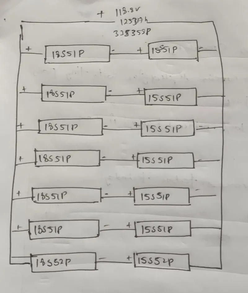
the battery pack is made of 33S358P pack so that it can meet the required output
As the number of cells in series and parallel are very high which makes manufacturing difficult. So, we need to divide it into sub battery packs and remake the connections to get the requried output
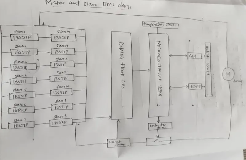
As the BMS Supports the max 18 cells in series so we need to divide the 33 sereis cells to 18 cells series sub battery pack which leads to 2 series sub connections one with 18 and another with 15
To make it compact parallel connectons we need to make 51 cells in parallel for each sub pack which leads to 7 parallel connections
Total result in 2 sub battery packs in sereis one with 18 cells in series and another with 15 cells in series and 7 sub battery pack in parallel each with 51 cells in parallel and any one with 52 to meet the requirment 33S358P.
One sub battery pack configuration is 18S51P and another sub battery pack configuration is 15S51P which results in 33S51P pack with 8 copies. these 7 33S51P are connected in parallel (One of the pack with 33S52P) to make 33S358P
Conclusion:
The battery pack was made to design as 33S358P divided into sub battery packs which is combination of 18S51P series with 15S51P, this combination is paralled with 7 copies as shown above toatl results in 33S417P with capacity of 150Kw with 120V.
To charge and discharge the Total battery pack Master and Slave BMS topology is used which is efficient in all ways like cost, design,control and instalation.
2.Build a 3S2P battery pack configuration with generic battery block using Matlab/Simulink
Aim:
Build a 3S2P battery pack configuration with generic battery block using Matlab/Simulink
The battery pack configuration is a setup in which we get the idea of the voltage and current generation with series and parallel connection variations. The Lithium-ion battery pack is the combination of series and parallel connections of the cell. In this blog batteries in series vs parallel we are talking about Series and Parallel Configuration of Lithium Battery. By configuring these several cells in series we get desired operating voltage. Also the Parallel connection of these cells increase the capacity which directly increase the total ampere-hour (Ah) rating of the battery pack.
Series Configuration
Some of the portable equipment requires higher voltage battery packs. so in thi case the voltage can increase by connecting these cell in series..
Prallel configuration
If the applications require the higher current capacity battery and larger cells are not available then by using the parallel configuration of these cells, the current capacity can increase.
to build a 3s2p battery pack we need the 6 cells and the 3 are connected in series and the 2 is connected parallel and as in the series connection as the all the cells are coonected in series and the voltage will be added as in the parallel the current capacity increases
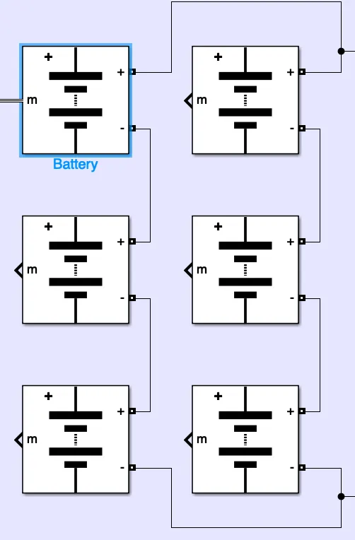
as we can see from above as the 3 cells are connected in series the negative terminal is connected with next cell postivie terminal as in the parallel connection all the postive terminals are connected together and as well as the negative terminal
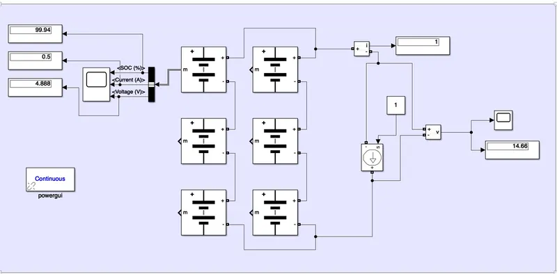
battery parameters:generic battery pack
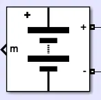
Nominal voltage (V)
The nominal voltage, Vnom, of the battery in V. The nominal voltage represents the end of the linear zone of the discharge characteristics. Default is 7.2.
Rated capacity (Ah)
The rated capacity, Qrated, of the battery in Ah. The rated capacity is the minimum effective capacity of the battery. Default is 5.4.
Initial state-of-charge (%)
The initial state-of-charge (SOC) of the battery. An SOC of 100% indicates a fully charged battery and 0% indicates an empty battery. This parameter is used as an initial condition for the simulation and does not affect the discharge curve (when the option Plot Discharge Characteristics is used). Default is 100.
Battery response time (s)
The response time of the battery (at 95% of the final value). Default is 30. This value represents the voltage dynamics and can be observed when a current step is applied.
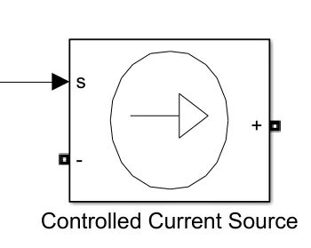
The Controlled Current Source block converts the Simulink® input signal into an equivalent current source. The generated current is driven by the input signal of the block.
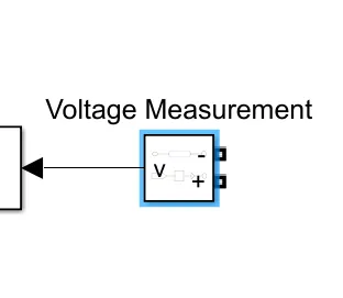
to measure the voltage between two terminals
To display the Values we are using
Powergui Block, make sure Simulation type must be in continuous mode.
from this battery model, we will get 3 output value
1. SoC%
2. Current &
3. Voltage
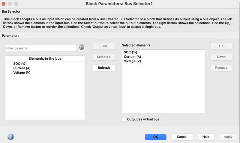
the battery output we connect to the bus selector from the bus selector we measure the all the outputs
1. This model displays the configuration 3S2P where the series 3 series are connected +ve terminal connected to all +ve terminals and 2 of these series connections are connected in parallel -ve to all -ve terminals.
2. The total voltage around the series connection is 4.2x 3 which is 12.6V as 4.2 is fully charged voltage which is connected in 3 series.
3. Total maximum capacity of each cell would be 2.5x2 as 2 cells connected in parallel which would be the total capacity of 5Ah
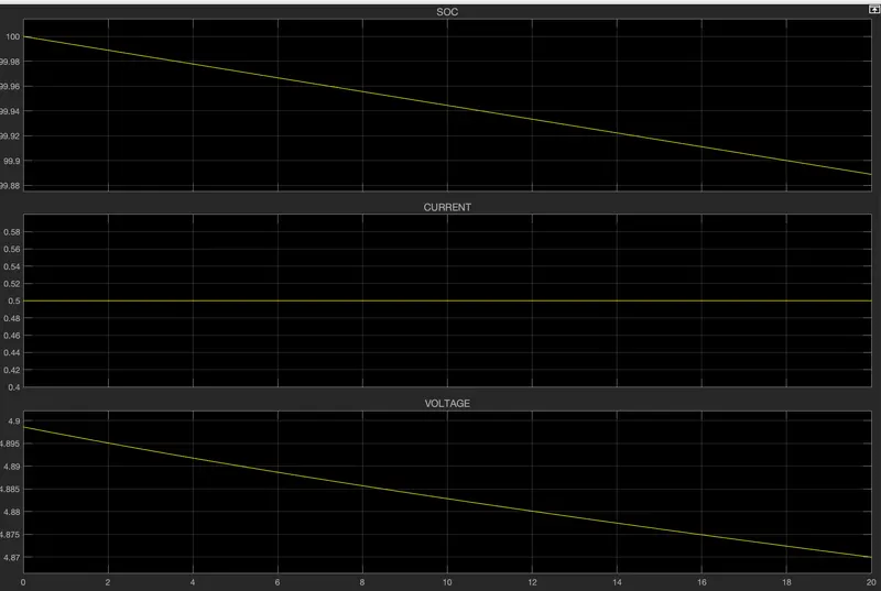
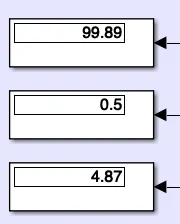
conclusion:as. from the above results we can see that the battery is fully loaded and as in the case of acceleration we pass the power the load we will be having the discharge in the voltage of the battery as well we can observe that the battery is getting discharge then for the 20 sec the the state of charge is about 99.89% and intially it was 100% which is fully charged and we can the current The Controlled Current Source block converts the Simulink input signal into an equivalent current source. The generated current is driven by the input signal of the block. and we from input current signal as the constant we given is as the 1 and it used as the load to it as we see in the scope or the display we getting only 0.5 because the current wil be dividing in parallel a parallel circuit acts as a current divider circuit because it divides all the current in its branches as we see the voltage as the output we will bw gettting the output voltage as 14.61 as we divide with 3 we get4.87 in the series connection acts as a voltage divider as in the above simulink model we connected the output of the only single of battery to the bus selector so we will get only the single cell voltage as displayed .