Project 1
Answer 1.
Aim of the Project:-
The Main Of this project is Design the battery pack configuration ,Draw the BMS topology for this battery pack using given data and also build 3s2p battary pack configaration by using the MATLAB/SIMULINK tool.
Theory:-
Battery Management Stysytem :-
A Bttery management system(BMS) is said to be the brain of a battery pack. The BMS is a set of electronics that monitors and manages all of the battery’s performance. Most importantly, it keeps the battery from operating outside of its safety margins.
The battery management system is critical to the battery’s safe operation, overall performance, and longevity of battery pack.
The primary function of the BMS is to protect the battery cells from damage caused by being overcharged or over-discharged. Additionally, the BMS calculates the remaining charge, monitors the battery’s temperature, monitors the battery’s health and safety by checking for loose connections and internal shorts.
The BMS also balances the charge across the cells to keep each cell functioning at maximum capacity.
Fig--> Battery management system
Solution :-
Given data:-
Required Power = 150 KW
Required Voltage = 120 V.
Battery detalis :-
Batatry capacity = 3500 mAh= 3.5 Ah
Battery Nominal Voltage =3.6V
a) Design the battery pack configuration.
for desiginig the Battery pack Configaration ,Firstly we have to fing the two parameters as followes :-
i) Number of cells connected in Series
ii) Number of cells connected in Parallel.
i) Number of cells connected in Series:-
For this solution let us Take the data from given:-.
Nominal volatge =3.6 v
Cell having capacity of cell(Ah)= 3500 mAh= 3.5 A
Formula:
Cells Connected in series = Required voltage (V) / Nominal cell Voltage (Ah)
From the data
Required Voltage :- 120 v
Nominal Voltage = 3.6 v
Therefore,
*** Cells connected in series = Required voltage (V) / Nominal cell Voltage(Ah) ***
The cells connected in series = 120 / 3.6
=33.3 cells
This Digits vallues are taken as rounding of caluctions as followes :
Rounding of calculation:-
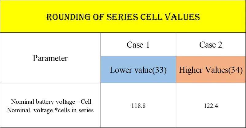
>>When compare with rated voltage, the battery voltage is greater in case 2 then case 1.
So,
No.of cell in series= 34 S
Number of cell connected In Series = 34S.....................(1)
ii) Number of cells connected in Parallel:-
Formula for number of cells connectd in parallel:-
Number of cell connectd in parallel:- Required contuinous Current (I) / Cell Nominal Voltage (V)
Given data:-
Required Power = 150 KW
Required Voltage = 120 V.
NMC Battery detalis :-
Batatry capacity = 3500 mAh= 3.5 Ah
Battery Nominal Voltage =3.6V
We know that ,
Power (P) = Current (I) * Voltage (V)
From Above Formula..
Current (I) = Power (P) * Voltage (V)
hence, From formula,
Current(I) = power(P) / Voltage(V)
= (150 *1000) / 120
Current(I) = 1250 Amps
NMC Battery detalis :-
Batatry capacity = 3500 mAh= 3.5 Ah
Battery Nominal Voltage =3.6V
Therefore,
Number of cells Connected in paralle :- Required contuinous Current (I) / Cell Nominal Voltage (V)
from the data ,
Current(I) = 1250 Amps
Cell nominal Voltage = 3.6 V
then ,
Number of cells Connected in paralle = Required Current (I) / Cell Nominal Voltage(V)
=1250 / 3.6
=358 P
There fore,
Number of cells Connected in paralle = 358 P......................(2)
From Value (1) & (2)
Number of cell connected In Series = 34 S
Number of cells Connected in paralle = 358 P
Rounding off to higher digit as extra current is also helpful
The required number of cells in parallel in 358
the battery configuration is 34S358P
may be we can split it to 2x17s and 2x179P
b).Battery Management System Topology:
Basically BMS topology is classified into following foure(4) types:-
1)Centralised Topology;-
This Topology is used for only pack of 18 cells or less than 18 cells in a series only.
2)Master and Slave topology:-
This Topology is used for pack of 18 cells or grater than 18 cells in a series .
High Energy storage purpose
3)Modular Topology :-
This Topology is used for pack of 18 cells or grater than 18 cells in a series .
Large Energy storage purpose
4)Distributed Topology:-
This Topology is used for pack of 18 cells or grater than 18 cells in a series .
Very large Large Energy storage purpose.
The above battery Configaration has 34 cells in series
it is above 8 cells in series so circular&distributed topologies is not used
it is below 7000 cells and to reduce cost modular topology is not used
we are using master and slave topology,
Here we mainly used the Master Salve topology because This architecture comprises of the Master and Slave BMS units.so by this The slave unit monitors balances and controls a group of battery cells within the battery module.It communicates with the master unit through a communication interface.The Master unit is responsible for state estimation control of Power Distribution Unit PDU and external communication.The master-slave BMS is similar to a modular system in the sense that it uses multiple identical modules the slaves each measuring the voltage of a few cells.However the master is different from the modules and does not measure voltages.It only handles computation and communications.
let us draw the Topology to understand more about the above battery configuration
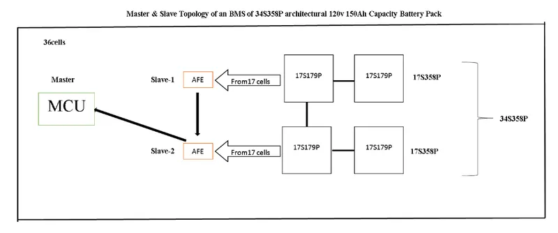
by observing the above topology
the slave 1 recieves the data from 17 cells connected to it and sends to slave 2
the slave 2 reads the data from 17 cells connected to it and from slave 1 and sends the data to master
The master reads the data from slave 2 which consists of the data of slave 2 and slave 1
thus the master manages the battery pack by collecting data
Importance of BMS Architecture for EV Battery Systems:
Measurement Precision
Connection Reliability
Expansion Versatility
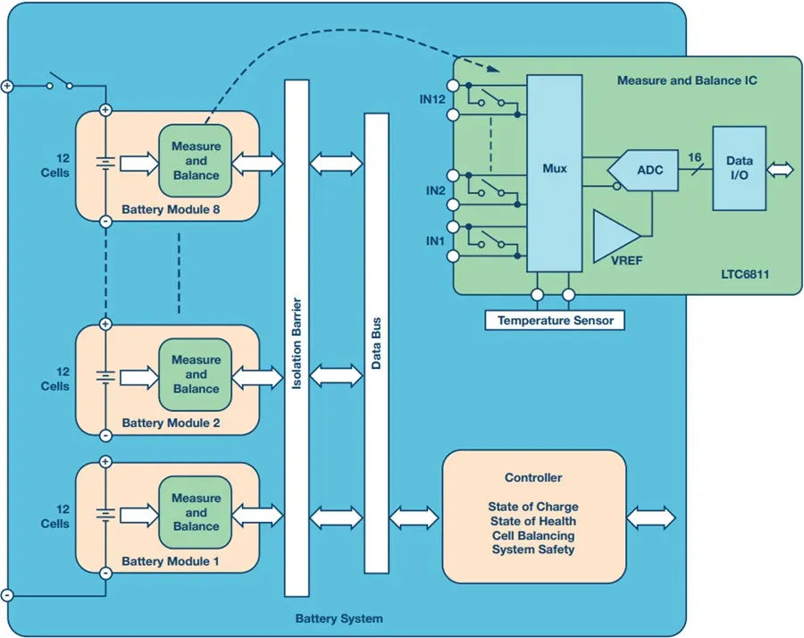
Here The main function of Battery Management System BMS is to ensure that the battery is protected and any operation out of its safety limit is prevented.
It monitors the battery pack's state of charge SOC along with the state of health SOH
Battery management system (BMS) is technology dedicated to the oversight of a battery pack, which is an assembly of battery cells, electrically organized in a row x column matrix configuration to enable delivery of targeted range of voltage and current for a duration of time against expected load scenarios. The oversight that a BMS provides usually includes:
Monitoring the battery
Providing battery protection
Estimating the battery’s operational state
Continually optimizing battery performance
Reporting operational status to external devices
Here, the term “battery” implies the entire pack; however, the monitoring and control functions are specifically applied to individual cells, or groups of cells called modules in the overall battery pack assembly. Lithium-ion rechargeable cells have the highest energy density and are the standard choice for battery packs for many consumer products, from laptops to electric vehicles.While they perform superbly, they can be rather unforgiving if operated outside a generally tight safe operating area (SOA), with outcomes ranging from compromising the battery performance to outright dangerous consequences. The BMS certainly has a challenging job description, and its overall complexity and oversight outreach may span many disciplines such as electrical, digital, control, thermal, and hydraulic.Battery management systems do not have a fixed or unique set of criteria that must be adopted.The technology design scope and implemented features generally correlate with:The costs, complexity, and size of the battery packApplication of the battery and any safety, lifespan, and warranty concerns.
Certification requirements from various government regulations where costs and penalties are paramount if inadequate functional safety measures are in place
There are many BMS design features, with battery pack protection management and capacity management being two essential features. We’ll discuss how these two features work here. Battery pack protection management has two key arenas: electrical protection, which implies not allowing the battery to be damaged via usage outside its SOA, and thermal protection, which involves passive and/or active temperature control to maintain or bring the pack into its SOA.
Electrical Management Protection: Current
Monitoring battery pack current and cell or module voltages is the road to electrical protection. The electrical SOA of any battery cell is bound by current and voltage. Figure 1 illustrates a typical lithium-ion cell SOA, and a well-designed BMS will protect the pack by preventing operation outside the manufacturer’s cell ratings. In many cases, further derating may be applied to reside within the SOA safe zone in the interest of promoting further battery lifespan.
conculsion:
We can conclude from above calculations.The battery Pack configaration is 34S358PBattry BMS Topology is "Master and Slave " Topology is is designed and explained thery regarding BMS topology.
Question 2:
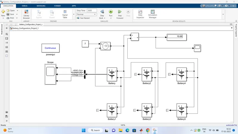
Aim: To build a simulink model of 3S2P battery configuration by using the generic battery block from special power systems in simscape blockset of MATLAB/SIMULINK
To build a simulink model first of all we have to know about the total number of cells that we are going to use
Total Number of cells=Number of cells in series×Number of cells in parallel
Total number of cells=3×2 = 6.
let us see the system level configuration
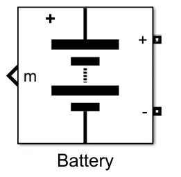
this is an generic battery from special powersystems segment of electrical in simscape library.
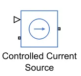
this is an controlled current source from the same library.
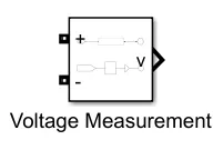
this is an voltage measurement block from the same library

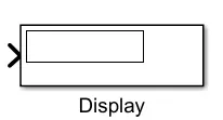
scope and display from foundation library
Model Parameters:
Battery:
Nominal Voltage = 3.6V
Max. Capacity = 3.5Ah
Total Voltage of the Battery = 3x3.6V=10.8V
Total Capacity of the Battery = 7Ah
Total simulation run time=3600s
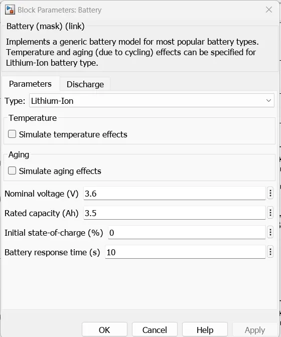
Simulink Module:
Procedure:
The given battery configuration 3S2P
I took the cell specifications of
Nominal Voltage 3.6V
capacity 3.5Ah
So the total vltage rating of the battery is 3x3.6V is 10.6V
capacity of the battery is 2x3.5Ah is 7Ah
the initial soc% is 0%
2 cells are connected in parallel in 3 pairs connected in series
the controlled source voltage is set to 7 to charge the battery
the simulink run time is set to 3600s
Now run the simulation model to see the simulation
Results:
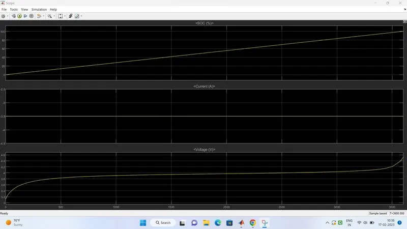
we can see individual cell SOC%, Current(A), and Voltage(V)
we can observe that the soc% increasing from 0 to 100%
as well as the voltage charging
let us see the overall battery pack nominal voltage
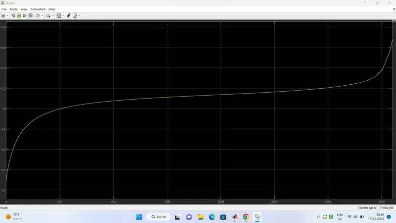
we can obesrve the voltage increasing gradually while charging.
Conclusion: The Batery Configuration for given battery specifications is designed and the BMS Topology is drawn.The Simulink Model for 3S2P Battery configuration with cell specification 3.6V, 3500mAh is built and simulated.