Project 1
Q.1 .
Aim - To design the battery pack configuration & also draw the BMS topology for this battery pack configuration.
(a)
for designing the battery pack configuration
Power of the car =150KW
voltage =120 V
power = volatage * current
150*1000=120*I
where I is the current across the battery pack.
so I = 1250 A
battery capacity =3500 mAh=3.5 Ah
Nominal voltage =3.6 V
No of cells in series =Total volatage /nominal voltage =120/3.6 =33.3.
No of cells in parallel = Total current /single cell current = 1250/3.5=357.1
so total cells needed = no of cells in parallel * No of cells in series = 357.1*33.3=11892.8.
So total number of cells = 11893.
(b ) Draw the bms topology for this battery pack
SO topology needs to be used here is Master slave topology beacause it consists of 18 numbers of cells in series .
here we can not used modular because it is used when a large number of energy storage applications are required .
we also can not use centralised topology because it consists of 18 or less number of cells in series .It generally used in small energy storage applications .
So finally topology used here is MASTER SLAVE TOPOLOGY .
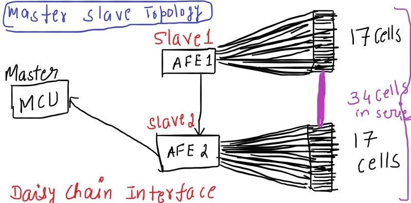
Pros of master slave topology
1.scalability possible
2.Can read ore than 18 cells max in series
CONS - Implementation is difficult in comparison to centralized topology.
Q.2 Build a 3S2P battery pack configuration
REQUIREMENT
1. we need three battery source in series it means that we have to make an end to end connection in the case of series connection .
2. when two nodes are common then it is called as parallel connection .In this we will makle common negative and positive of battery will also be connected as common.
3. we need one controlled current source.
4. One bus selector is needed .
so in simulink
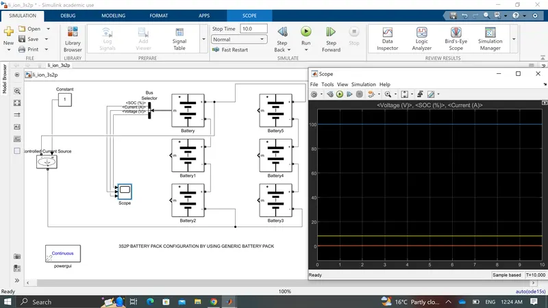
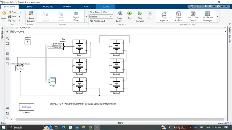
BY THIS WAY WE CAN DESIGN 3 SEREIS AND TWO PARALLEL BATTERY PACK CONFIGURATION BY HAVING 3 SERIES AND TWO PARALLEL PACKS BY HAVING POITIVE AND NEGATIVE AS COMMON .