Project 1
Aim :-
Develop a double-acting actuator model using Simscape Multibody and Simscape components.
Objectives :-
The mechanical system of the cylinder needs to be built using Simscape Multibody library components/blocks, and the hydraulic system needs to be modeled using Simscape library physical components.
Theory :-
The schematics show the cylinder in three configurations: half-retracted, fully retracted, and fully extended.
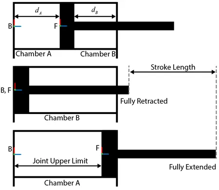
Working Of Double Acting Hydraulic Actuator :-
Double-acting hydraulic cylinders have a Cylindrical housing and one piston. When hydraulic oil is supplied to its cap end port, hydraulic pressure force will be applied over the piston and the end cylinder will be extended. During the extension of the piston hydraulic oil at the rod, the end side will be pushed out and directed towards the reservoir.
For the returning stroke, the hydraulic direction is reversed with the help of the direction control valve. During the returning stroke hydraulic oil is supplied to the rod end side and hence piston is retracted. During the retracting of the piston cap end, oil is directed toward the reservoir. hence the double-acting hydraulic actuator operated in both the directions.
Model :-
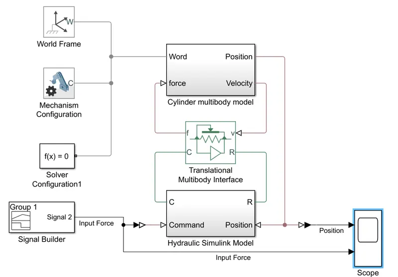
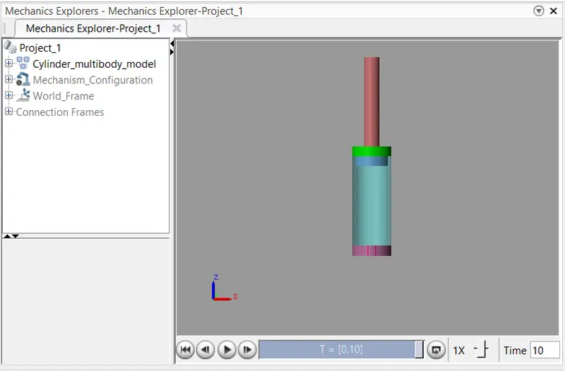
Cylindrcal Multibody Model :-
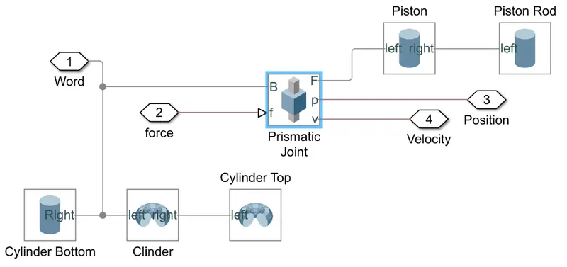
Hydraulioc Simulink Model :-
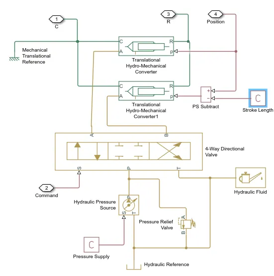
Used block details given below.
Prssure Supply :-
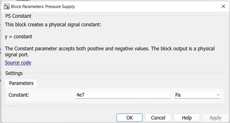
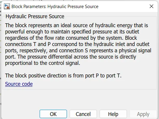
As we need constant pressure supply ps-constant block used along with Hydraulic pressure source block with pressure 4e7 Pa. Block parameter given as below.
PS Constant -
Hydraulic Pressure Source -
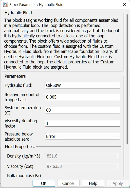
Hydraulic Fluid :-
Hydraulic fluid Oil-50W is used for hyadraulic actuator working. Block parameter are given below.
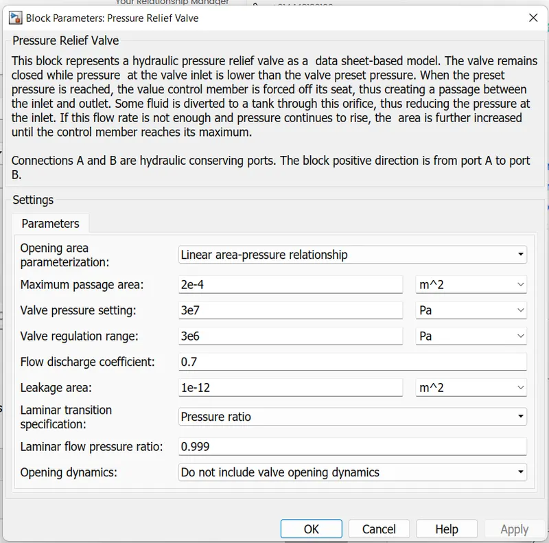
Pressure Relief Valve -
Pressure relief valve is used for controlling the pressure of fluid for smooth working of hydraulic actuator. Parameters of given below.
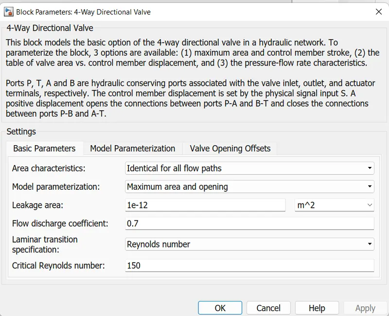
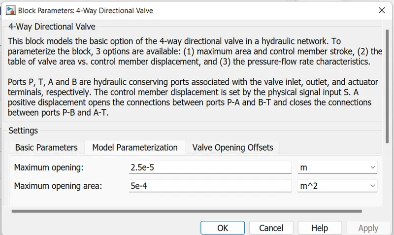
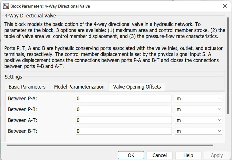
4-Way Directional Valve -
To Control flow of fluid as per requirement to hydraulic actuator 4-Way directional Valve is used. Input signal given from signal builder to port S. P port is connected to pressure supply & T port is connected to hudaulic fluid unit. A & B port output is connected to hydro-mechanical conveters. Parmeters are given below.
Translational Hydro-Mechanical Converter -
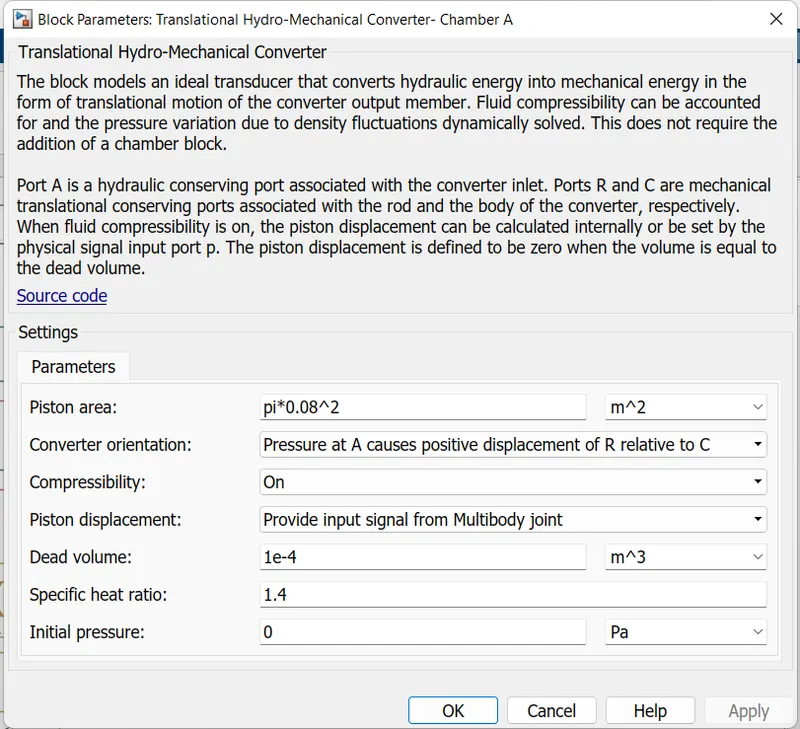
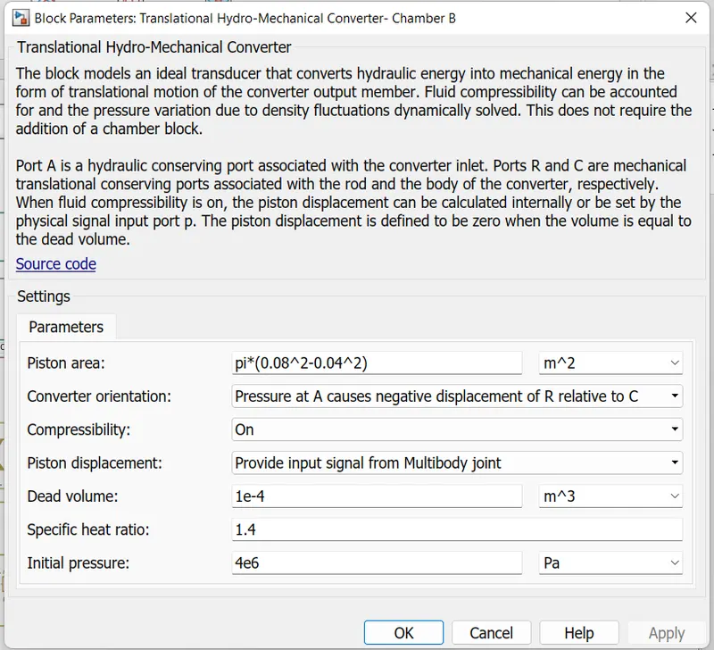
This block is used for converting hydaraulic pressure energy to mechanical actuation of hydraulic actuator for both Chamber A & B in positive & negative directions. Hydraulic atuator position feedbacke subtracted form stroke length is given to chameber B & Position feedback given to chamber A as input to port P. R & C ports are connected to R & C ports translational multibody interface respectively. Parameter of both chambers are as follows.
Chamber A -
Chamber B -
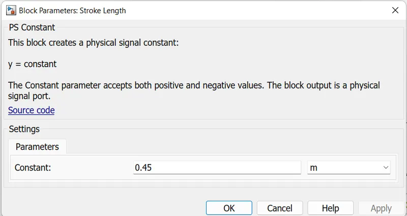
Stroke length :-
Stroke length is given as hydraulic actuator displacement in cylinder between Cylinder bottom & Cylinder top by PS Constant block as 0.45m.
Cylinder Unit :-
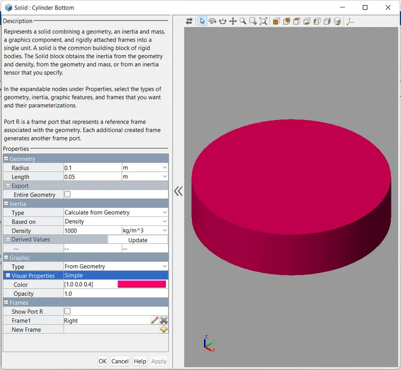
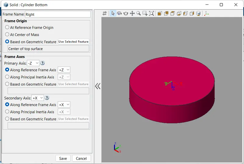
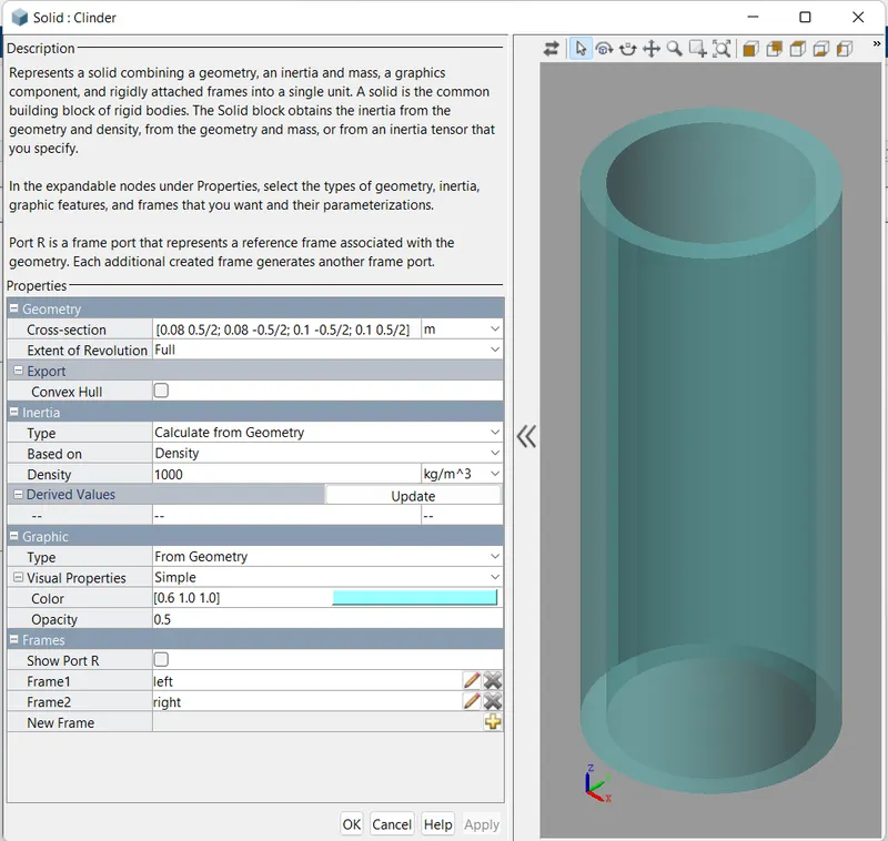
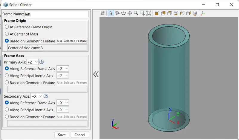
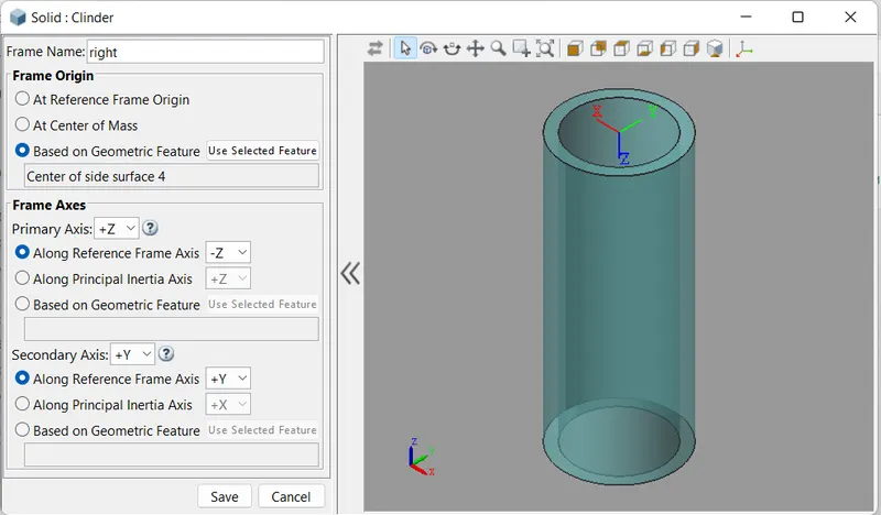
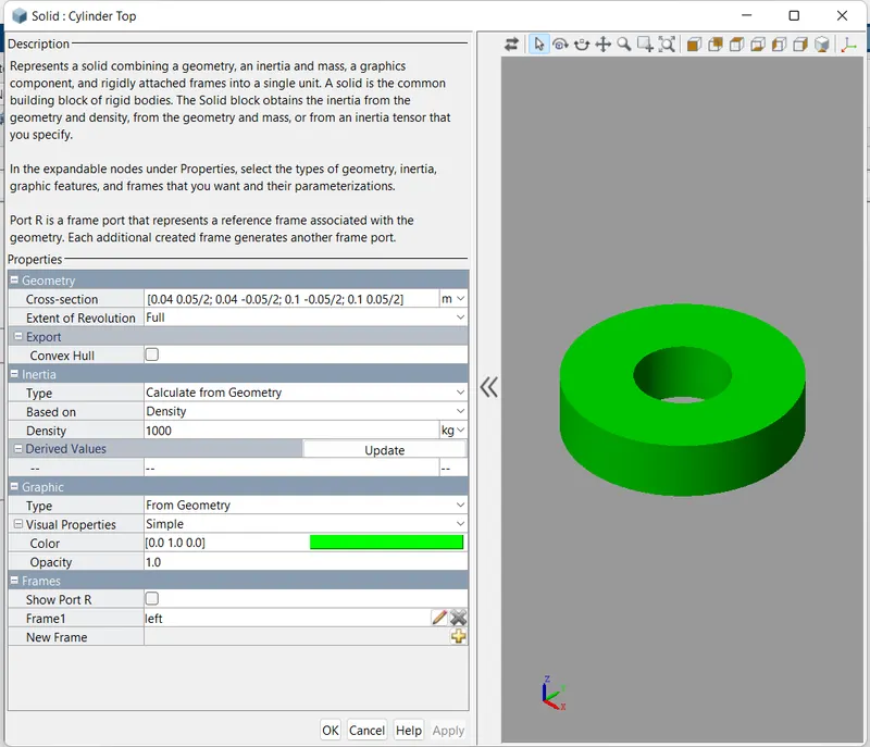
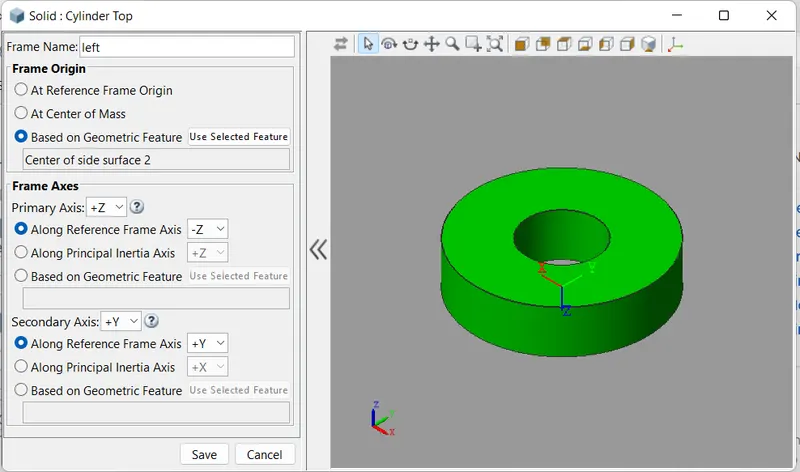
Cylinder unit consist of cylinder, cylinder bottom & cylinder top build using simscape multibody elements. Cylinder bottom is bulid by Cylindrical Solid block from multibody- Body elements library. Cylinder and Cylinder top is build from Revolved solid from multiboby- body elements library. Both cylider top & cylinder bottom are connected to cylinder throuh frames.
Cylindrcal unit is connected to B port of prismatic joint. Also connected to mechanical configuration, solver configuration & world farme.
Parameters of each block given below.
Cylinder Bottom :-
Cylinder -
Cylinder Top -
Piston & Piston Rod Assembly :-
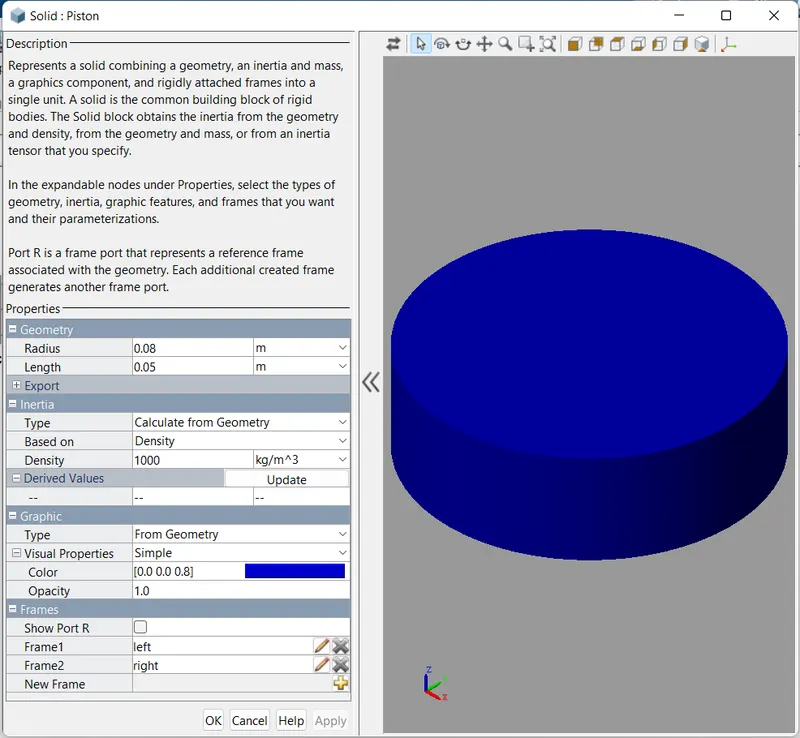
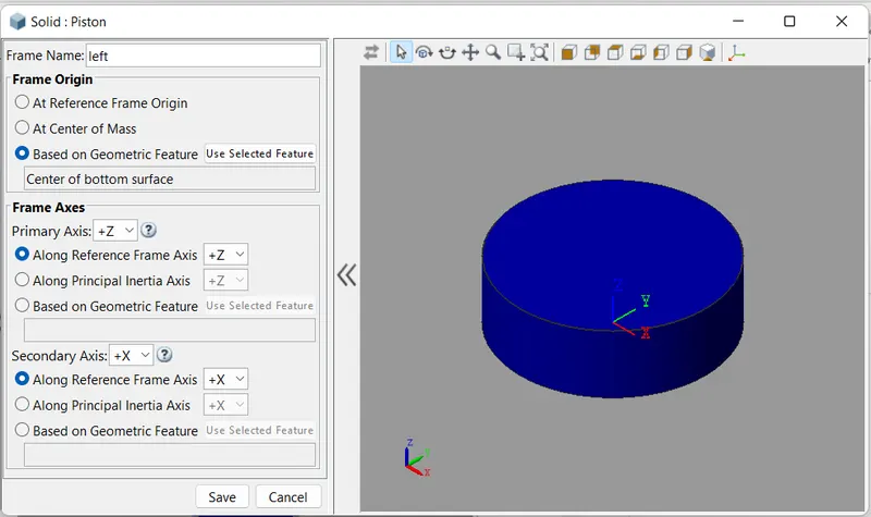
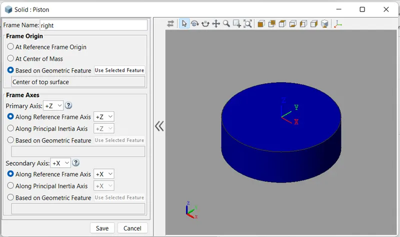
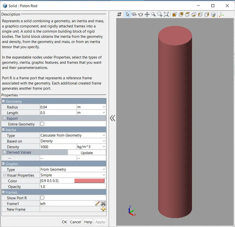
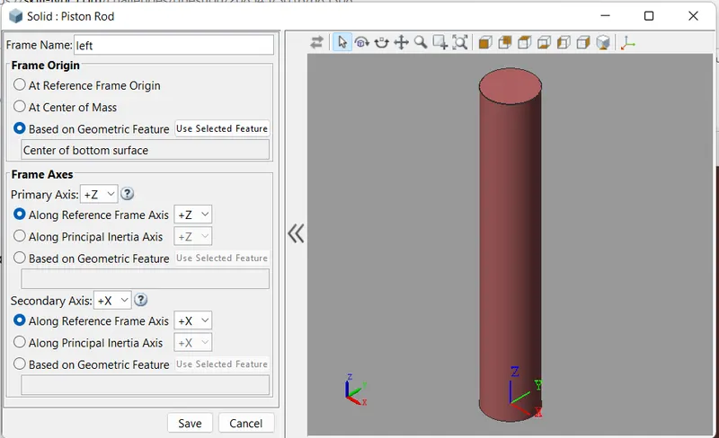
Piston and piston rod assembly is connected to F port of Prismatic joint for piston movement. Both piston & piston rod are bulid by Cylindrical Solid block from multibody- Body elements library. The paramerer of both block are as follows.
Piston -
Piston Rod -
Prismatic Joint -
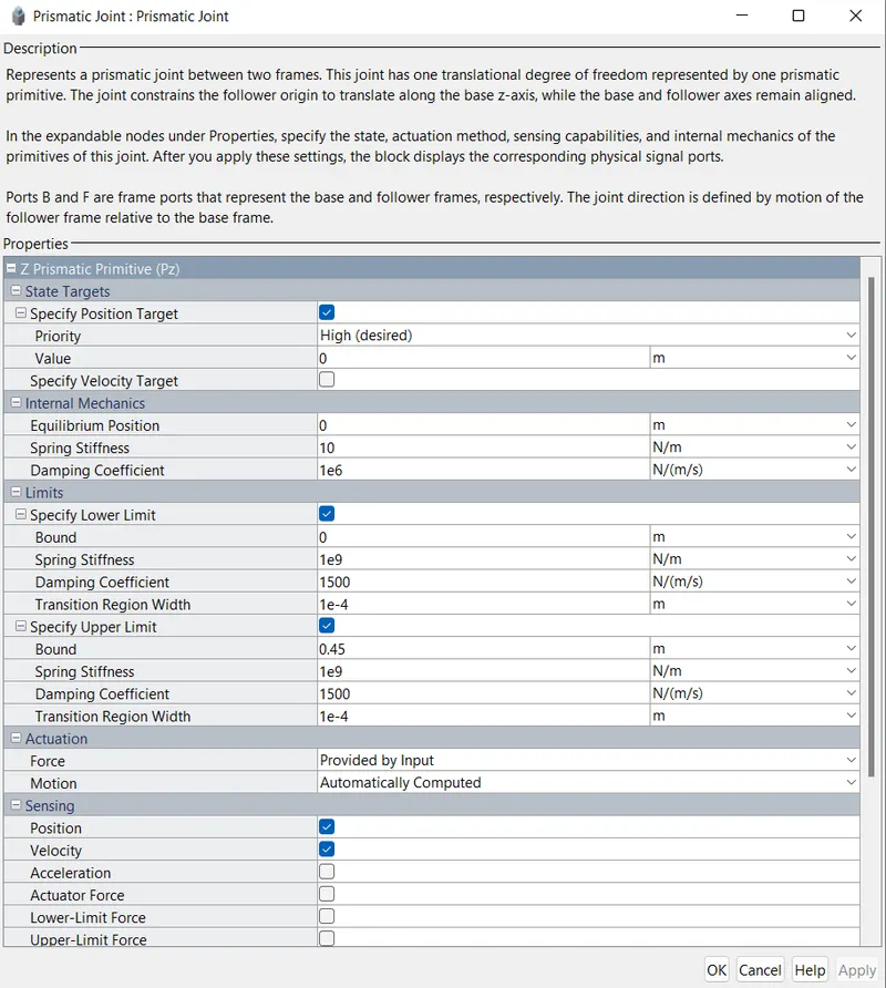
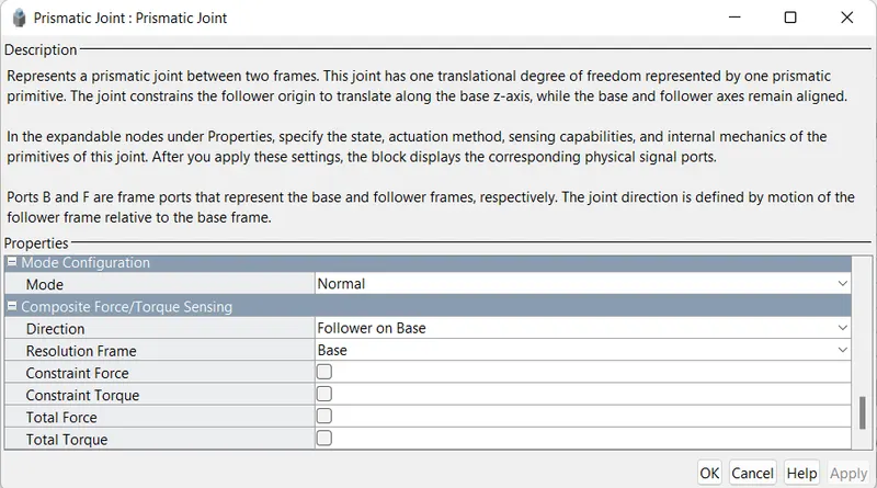
Prismatic joint block is used for controlling motion of piston assembly. Port B is connected to Cylinder assembly, Port F is connected to Piston Assembly, port p is connected to translational hydro-mechanical convrter uint as position feedback, port v is connected to translational multibody Interface as velocity feedback & port f is conncted from translational multibody Interface as force input. The parmaeters of block are as follows.
Translational Multibody interface :-
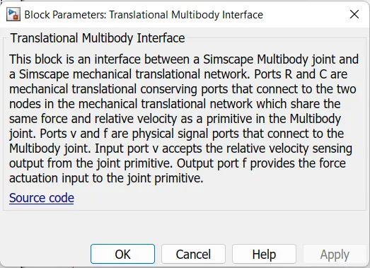
Both cylinder multibody & Hydraulic simulink model is connected through Translational Multibody interface.
Input Force -
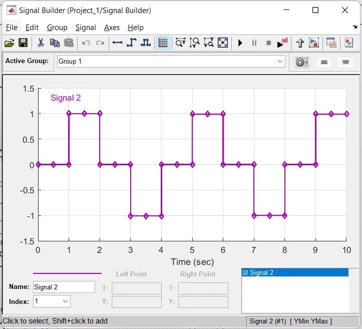
Input force for spool valve to operate hydraulic unit is given by signal builder. Input force signal is given below.
Screenshot of mechanics explorer -
Screenshot of Scope output -
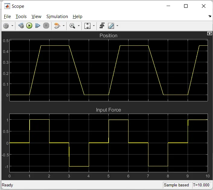
According to input signal actator position vairies.