Project 1
Aim: To Design the Mathematical Model of a Three-Phase Induction Motor using Simulink and plot different parameters for different reference frames with given specifications
Dynamic Simulation is one of the most important processes in the validation of the motor drive system's design process, as it eliminates design errors and the resultant problems in prototype fabrication and testing.
Let us assume that the Airgap is uniform, the construction is a squirrel cage type, windings in the stator and rotor are balanced and distributed sinusoidally, and saturation and parameter variation is not taken into account
let us see the block diagram of the dq0 equivalent circuit of Three phase induction motor
let us convert three-phase to dq0(two-phase) so that we can generate fluxes
For the squirrel cage induction motor, the rotor voltages `V_(qr)andV_(dr)` in the flux equations are set to zero since the rotor cage bars are shorted.
The three-phase stator voltages of an induction machine under balanced conditions are expressed as
`V_a=sqrt2V_(rms)sin(omegat)`
`V_b=sqrt2V_(rms)sin(omegat-(2pi)/3)`
`V_c=sqrt2V_(rms)sin(omegat+(2pi)/3)`
The three-phase voltages are transferred to a synchronously rotating frame in only two phases(d-q axis transformation) This can be done using the following equations
`[(V_(alpha)),(V_(beta))]=2/3[[1,1/2,-1/2],[0,sqrt3/2,-sqrt2/2]][(V_a),(V_b),(V_c)]`
Then the direct and quadrature axes voltages are
`[(V_d),(V_q)]=[[costheta,sintheta],[-sintheta,costheta]][(V_(alpha)),(V_(beta))]`
this can be modeled in the simulation as
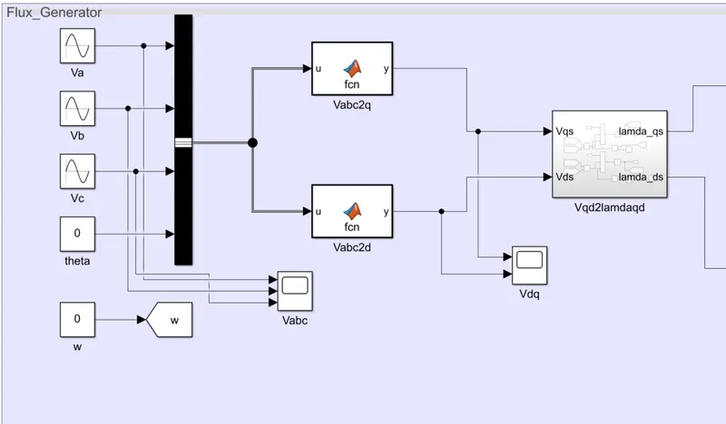
The MatLab function is having conventions that let us see the conversions

the above function is for converting abc to q axis
let us see the d-axis conversion too

The instantaneous values of the stator and rotor currents in a three-phase system are ultimately calculated using the following transformation
`[(i_(alpha)),(i_(beta))]=[[costheta,sintheta],[-sintheta,costheta]][(i_d),(i_q)]`
and
`[(i_a),(i_b),(i_c)]=2/3[[1,0],[-1/2,-sqrt3/2],[-1/2,sqrt3/2]][(i_(alpha)),(i_(beta))]`
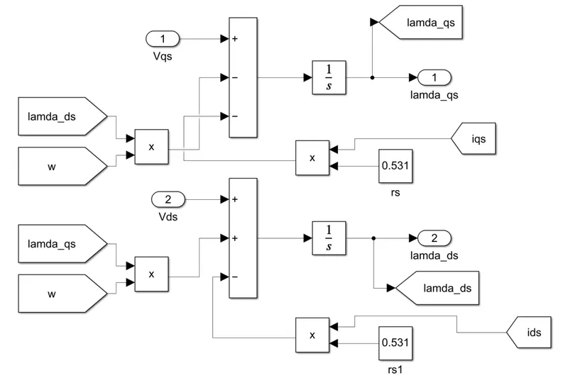
The flux linkages equations associated with the above equivalent circuit is shown below
`(dpsi_(qs))/(dt)=omega_b[V_(qs)-omega_e/omega_bpsi_(ds)+R_s/X_(ls)(psi_(mq)-psi_(qs))]`
`(dpsi_(ds))/(dt)=omega_b[V_(ds)-omega_e/omega_bpsi_(qs)+R_s/X_(ls)(psi_(md)-psi_(ds))]`
where
`psi_(mq)=X_(ml)[psi_(qs)/X_(ls)+psi_(qr)/X_(lr)]`
`psi_(md)=X_(ml)[psi_(ds)/X_(ls)+psi_(dr)/X_(lr)]`
`X_(ml)=1/((1/X_m+1/X_(ls)+1/X_(lr))`
The flux linkages are modeled in the Simulink as follows
Then substituting the values of the flux linkages to find the currents
`i_(qs)=1/X_(ls)(psi_(qs)-psi_(mq))`
`i_(ds)=1/X_(ls)(psi_(ds)-psi_(md))`
`i_(qr)=1/X_(lr)(psi_(qr)-psi_(mq))`
`i_(dr)=1/X_(lr)(psi_(dr)-psi_(md))`
and also the rotor flux linkages are given by
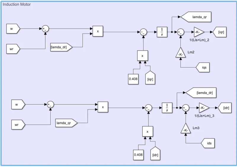
`(dpsi_(qr))/(dt)=omega_b[V_(qr)-(omega_e-omega_r)/omega_bpsi_(dr)+R_r/X_(lr)(psi_(mq)-psi_(qr))]`
`(dpsi_(dr))/(dt)=omega_b[V_(dr)-(omega_e-omega_r)/omega_bpsi_(qr)+R_r/X_(lr)(psi_(mq)-psi_(dr))]`
The above stator and rotor currents and the rotor flux linkages are given by
Now Based on the above equations, the torque and rotor speed can be determined as follows:
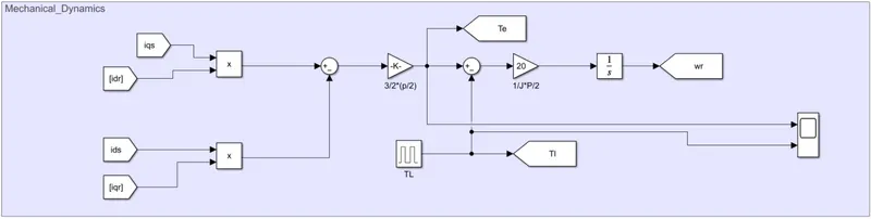
`tau_e=3/2(P/2)1/omega_b(psi_(ds)i_(qs)-psi_(qs)i_(ds))`
`omega_r=intP/(2J)(tau_e-tau_L)`
the mechanical dynamics of the motor are given by
let us design the reference frames so that we can switch to the desired reference frame
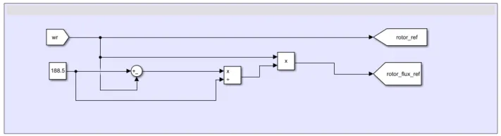
a): stationary d-q reference frame:
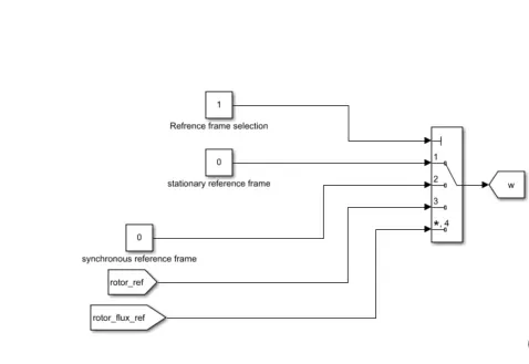
at the stationary d-q reference frame the speed is considered to be zero
the reference frame selection is made like
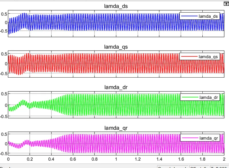
let us see the output characteristics
the voltage linkages are shown as
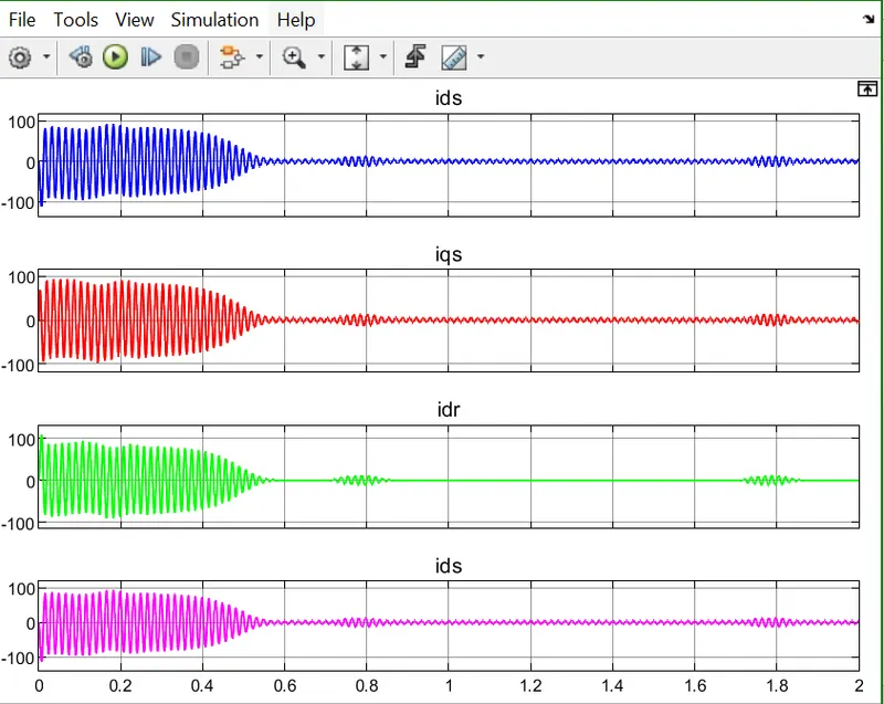
the currents are shown as
the torques are shown as
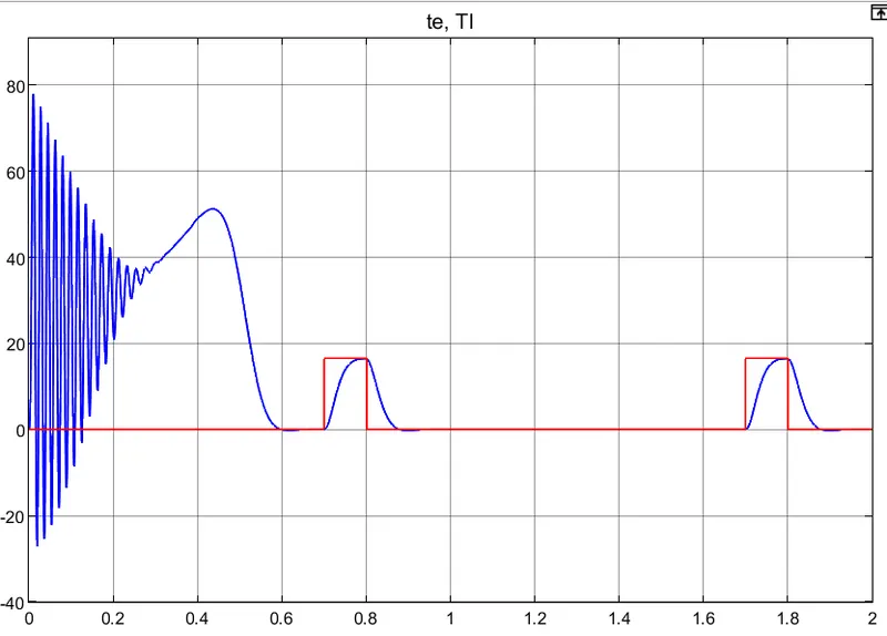
the rotor speed is given by
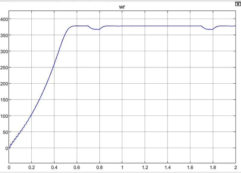
b): synchronous reference frame:
let us select the synchronous reference frame as follows
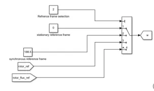
let us see the output characteristics
the flux linkages
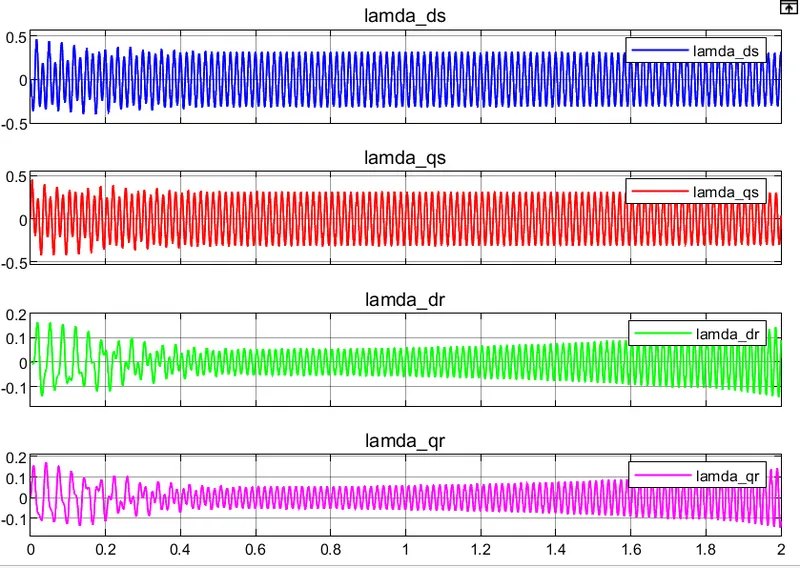
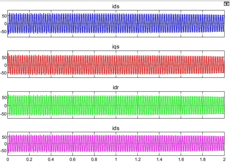
the currents are given by
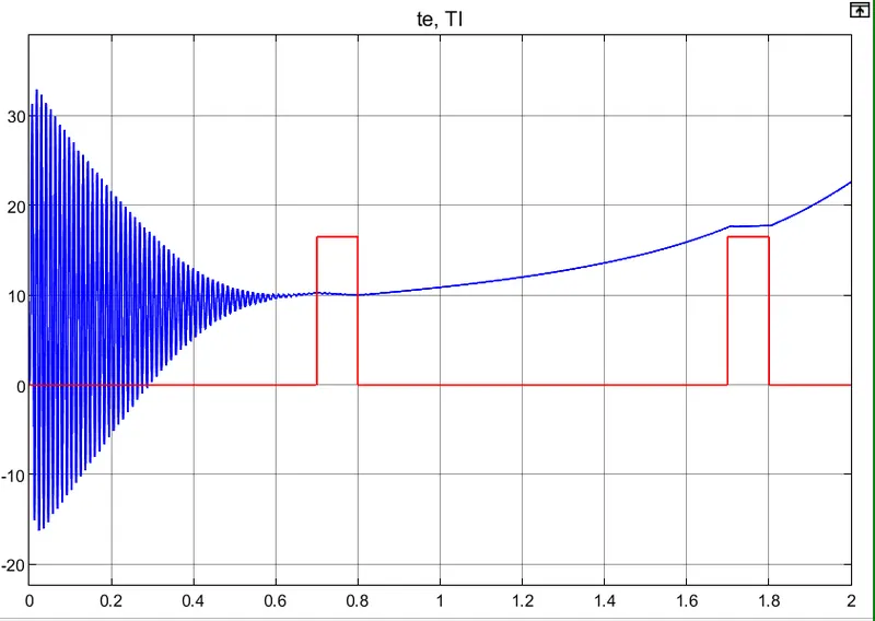
the torques are given by
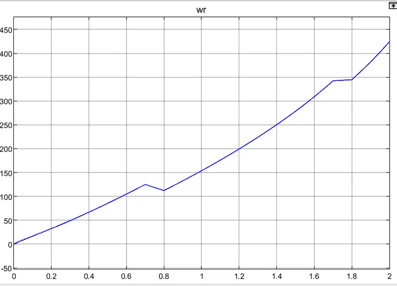
the rotor speed is given by
C): rotor reference frame:
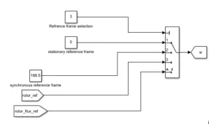
let us select the rotor reference frame as follows
the flux linkages are given by
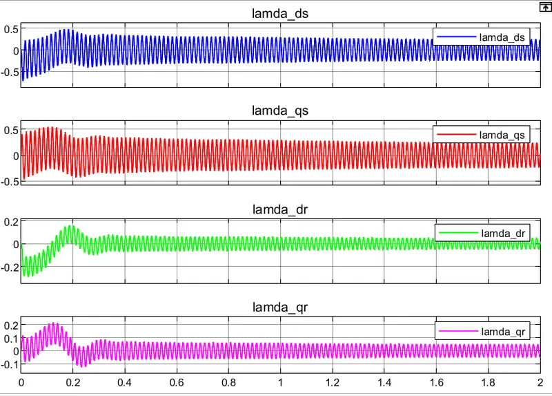
the currents are given by
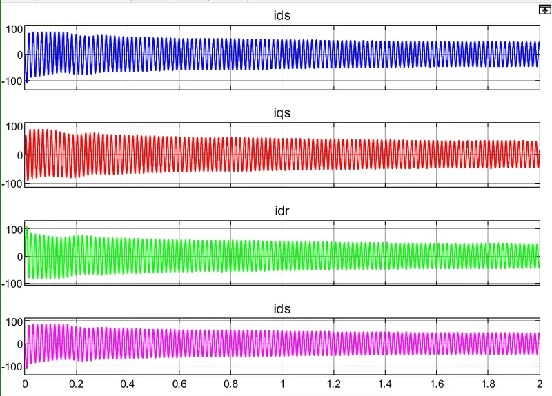
the torque are given by
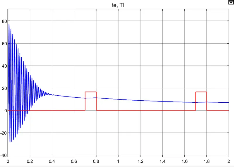
the rotor speed is given by
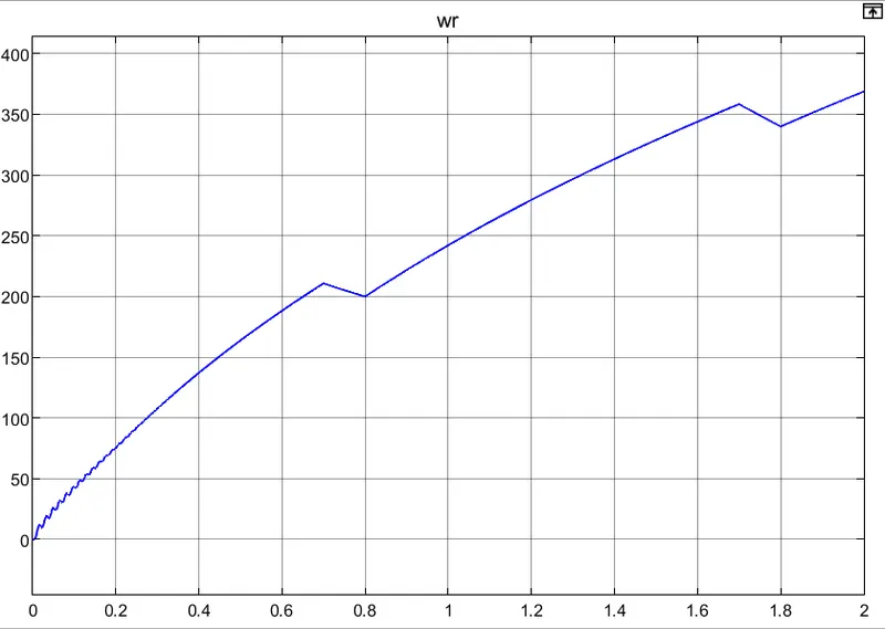
D): Rotor flux reference frame:
the rotor flux reference frame is given by

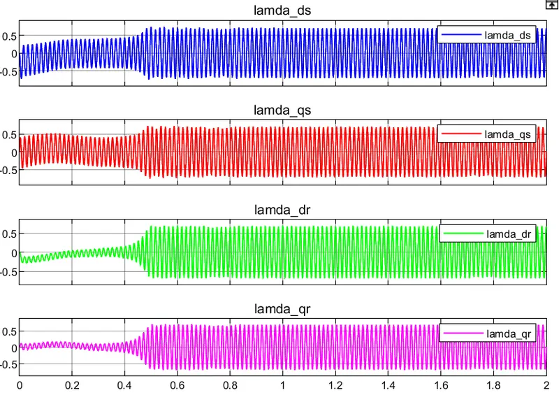
the flux linkages are given by
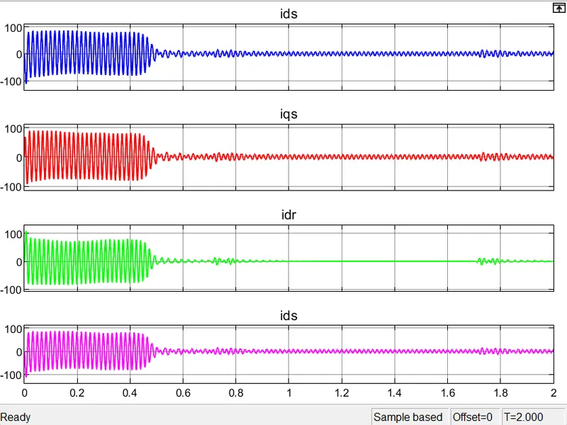
the currents are given by
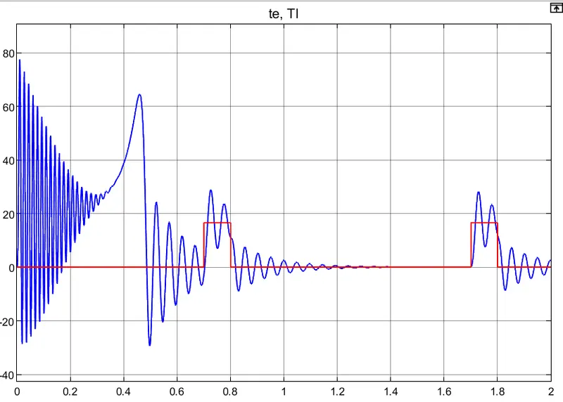
the torques are given by
the rotor speed is given by
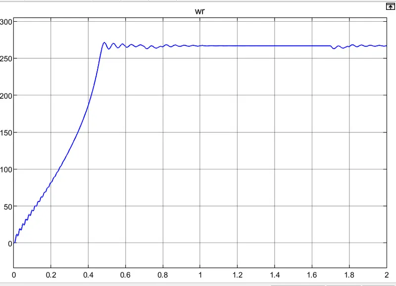
by observing all the reference frames the different speed profiles are applied and the flux linkages and currents of the d-q axes of the stator and rotor and also the electromagnetic torque of the motor varies by changing the reference frames.
Conclusion: The given specifications are applied to the mathematical model of the induction motor by using the Simulink and different reference frames are applied so that the flux linkages, currents, and torque as well as the rotor speed characteristics are observed