Project 1
Given;
Power = 150 kW
Voltage = 120 V
Capacity = 3500 mAh = 3.5 Ah
Nominal/single cell voltage = 3.6 V
Then, the no. of cells in series = Total voltage/single cell voltage = 120/3.6 = 33.34 = 34 cells.
Power = V*I
I = Power/Voltage = 150000/120 = 1250 A
No. of cells in parallel = Current/Capacity = 1250/3.5 = 358 cells
So, there are 34 cells in series and 358 cells in parallel
ie, the battery pack configuration is 34S 350P.
BMS topology :
The BMS is a system that works in an integrated fashion with other devices such as a battery charger, sensors and the battery pack itself. The topology of BMS could be either centralized, distributed or modular. The centralized topology would include one control unit that is connected to each cell in the battery pack through separate wiring.
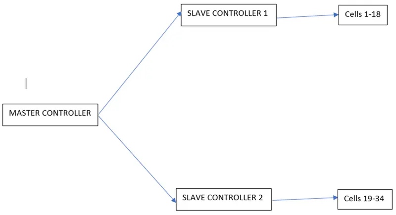
As there are about 34 cells in series in the battery pack, we have to use Master-Slave topology as the BMS topology in which Master/slave is a model of communication for hardware devices where one device has a unidirectional control over one or more devices. This is often used in the electronic hardware space where one device acts as the controller, whereas the other devices are the ones being controlled.
Here, a master controller is connected to 2 slave controllers with their respective AFEs , where the first slave controller is having 18 cells (maximum cells that can be connected to an AFE) and the second controller is having 16 cells.
The major communication protocols that you may use or find when working with a battery management system.
When working with a BMS, you usually use a BMS IC. Depending on the BMS IC being used to control your BMS, you may need to connect to an external microcontroller or another external IC.
These ICs need to be able to communicate with each other to send and/or receive information from one another. For example, you may have a BMS IC that doesn't have the capability of measuring current. Therefore, you use an external IC that measures current. This current data then needs to be fed to the BMS IC. Or, another example, is you have a microcontroller connected to the BMS IC that reads the data from the IC to make decisions governing the BMS.
So communication protocols are vital for a battery management system with multiple ICs to be able to communicate with each other.
Communication Protocols for a Battery Management System (BMS)
- UART. UART, which stands for Universal Asynchronous Receiver/Transmitter, is the most widely used communication protocol...
- I2C. I2C, Inter-Integrated Circuits communication, is a protocol used for IC to IC communication. I2C is intended...
- SPI. SPI, Serial Peripheral Interface, is a master-slave type protocol that provides a simple and low cost interface...
- CAN. CAN, Controller Area Network, is the most widely used communication protocol in the automotive.
Blocks used in the model:
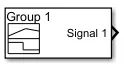 |
Signal builder block used to create a desired input signal with respect to simulation time |
 |
Controlled current source used to create the current signal corresponding to the given physical input signal. |
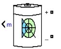 |
The Battery block implements a generic dynamic model that represents most popular types of rechargeable batteries. |
 |
This block represents voltage measurement used to measure the voltage across the connected terminals. |
 |
Scope used to plot the obtained results with respect to the simulation time. |
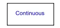 |
The powergui block allows you to choose one of the methods to solve the circuit.
|
 |
Demux block used to split vector signals into scalars or smaller vectors. Check 'Bus Selection Mode' to split bus signals. |