Project 1
Project-1
Question: -1
- Design only a Main Frame with Lean (Grid 2) & Gable Frame without Lean (Grid 15)
Assume purlin load as 8.77 kg/m
Assume Gantry girder wt. = 158.24 kg/m
Assume Rail weight = 53 kg/m
Aim:- To Model and Desogn a Proposed Coil Centre in Chennai using STAAD Pro.
Procedure:-
Step 1:-
First we have model and design a Main Frame with Lean (Grid 2).
Open STAAD Pro Software, and create a new file.
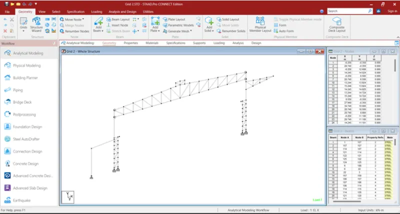
In Geometry Tab, Create a Main frame model using Nodes, Beams and Mirror commands as shown below.
Step 2:-
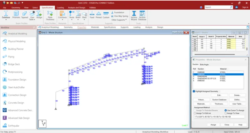
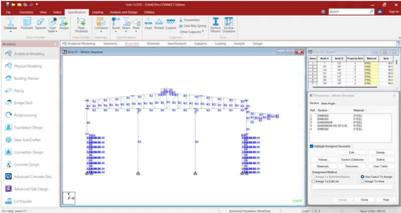
Select Properties Tab, and create a Sections in Section Database.
And Assign the sections to the members as shown below.
Step 3:-
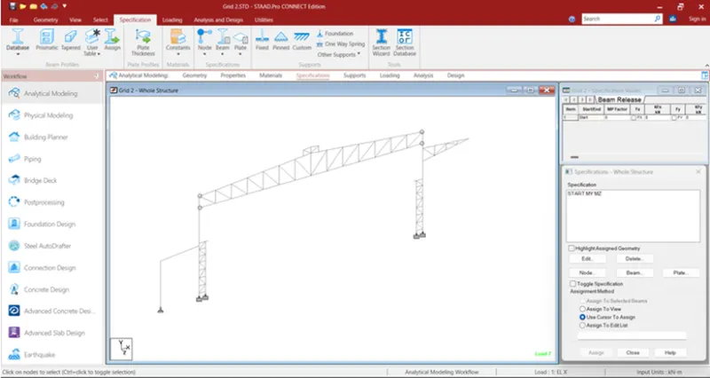
In Specification tab, create and assign the Moment Release to the required beams.
Step 4:-
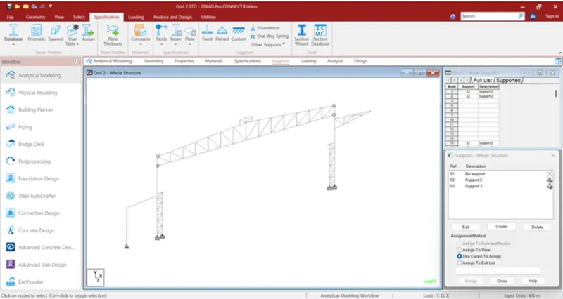
Select Support Tab, create Fixed and Pinned Supports.
Then assign the Fixed support to Main Frame column and Pinned support Lean column.
Step 5:-
Then Prepare inputs for loads.
Dead Load Calculation:
Given data:-
Dead Load = 0.14 kN/m2 (for main portion without false ceiling)
Collateral Load = 0.15 kN/m2
Total Dead load = 0.14 + 0.15 kN/m2 = 0.29 kN/m2 (for roof extension)
Let’s Assume Purlin and Girt weight as 8.77 kg/m
Bay Spacing = 10m
Therefore,
Purlin Load on Roof = 8.77 x 10/2 = 43.85 kg = 0.44 kN
Purlins on Wall:
Total number of Purlin in Near Side wall = 5
Total number of Purlin in Near Side wall (Crane supported column) = 3
Total number of Purlin in Far Side wall = 2
Therefore,
Purlin Load on NSW = 5 x 8.77 / 6.1 = 7.2 kg/m2 = 0.072 kN/m2
Purlin Load on NSW = 3 x 8.77 / 3.5 = 7.52 kg/m2 = 0.075 kN/m2
Purlin Load on FSW = 2 x 8.77 / 2.1 =8.35 kg/m2 = 0.0835 kN/m2
Total DL over truss = (0.14) x 10 = 1.4 kN/m
Total DL over Cantilever portion = (0.29) x 10 = 2.9 kN/m
Total Dead load on NSW = (0.14 + 0.072) x 10 = 2.12 (above crane supporting column)
Total Dead load on NSW = (0.14 + 0.075) x 5 = 1.075 (in crane supporting column)
Total Dead load on FSW = (0.14 + 0.0835) x 10 = 2.24 (on wall above cantilever)
Gantry weight = 158.24 kg/m
Rail weight = 53 kg/m
Weight on bracket = 211 x 5 = 1056 kg = 1056 kN
Lattice tie of 200 kg is between the column
Load on column = 200 /2 = 100 kg = 1kN as joint load
Totally 9 Purlins
Load on column due to Purlins = (9 x 8.87 /11.1) = 7.2 kg/m2 = 0.072 kN/m2
Load on column = 0.072 + 0.14 = 0.212 kN/m2 = 0.212 x 10 = 2.12 kN/m
Live Load Calculation:
Given data:-
Live Load = 0.75 kN/m2
Live Load on Rafter = 0.75 x 10 = 7.5 kN/m
Wind Load Calculation as per IS 875 Part III:
Given data:-
Wind speed = 50m/s
K1 = 1; K2 = 0.94 (terrain category 3); K3 = 1; K4 = 1.15 (cyclone zone)
Ka = 1; Kd = 0.9; Kc = 0.9
Basic wind speed Vb = 50 m/s ( For Chennai as per IS 475 part-3 Fig. 1)
Design wind speed Vz = Vb x K1 x K2 x K3 x K4
Therefore Vz = 1.0 x 0.94 x 1.0 x 1.15 x 50 = 54.05 m/s
Wind pressure Pz = 0.6 (Vz)2
Where,
Pz = wind pressure at height z in N/m2
Vz = design wind pressure at height z in m/s
Therefore
Pz = 0.6 x (54.05)2 = 1.752 kN/m2
Design wind pressure Pd = Kd x Ka x Kc x Pz
Therefore
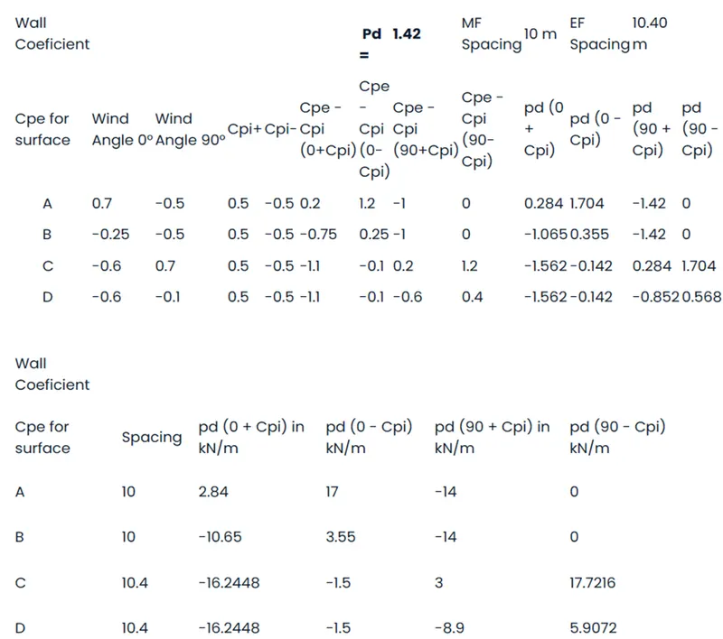
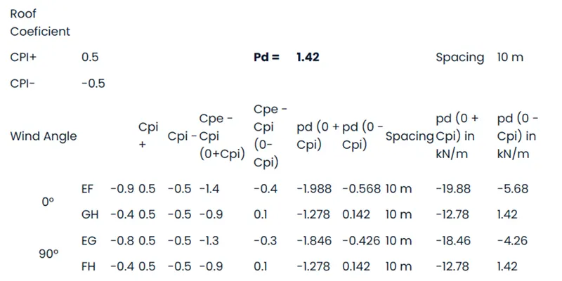
Pd = 1.0 x 0.9 x 0.9 x 1.752 = 1.419 kN/m2
Wind load acting in a direction normal to the individual structural element or cladding unit
F = (Cpe – Cpi) x A x Pd
Where,
Cpi = internal pressure coefficient
Cpi = +0.5 and -0.5 for opening of 15% of wall area i.e. medium permeability (Clause 7.3.2.2 of IS :475, part 3)
External pressure coefficient:
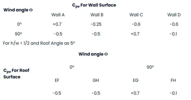
L = 140 m; w = 41 m; h = 11.7 m
h/w = 11.7 / 41 = 0.29
l/w = 140 / 41 = 3.41
Thus as per table 5 of clause 7.3.3.1 of IS:475, Part 3
For h/w < 1/2 and 3/2 ≤ l/w < 4
For Cantilever portion alone reduction due to area averaging.
Ka = 0.85 (since tributary area is 10 x 6 = 60 m2)
Thus kd x ka x kc < 0.7 Taken as 0.7 (upper limit)
Pd = 0.7 x 1752.8 = 1.23 kN/m2
Crane Load Calculation:
Capacity = 30MT
Selfweight = 35MT
Vertical impact = 1.25
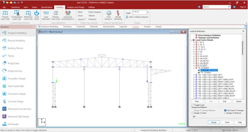
Load for Left end = 1.25 (300 + 175) = 593.75 kN
Lateral Impact = 0.2 x Crane Weight = 0.2 x 35 = 7 kN
Half of the Selfweight of Crane acting on the other side.
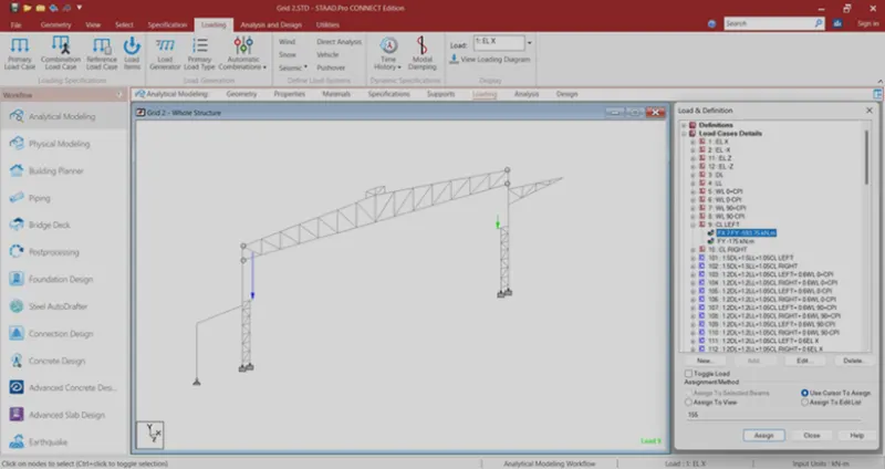
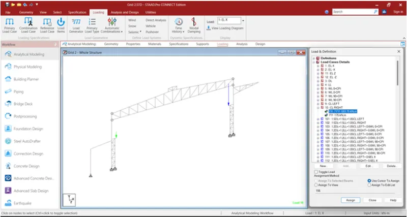
Step 6:-
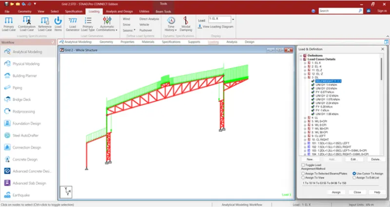
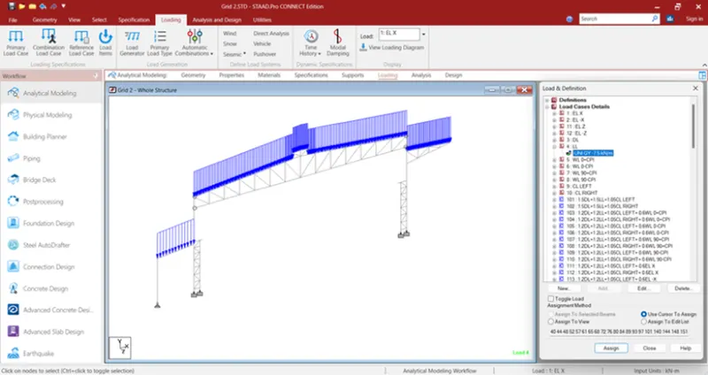
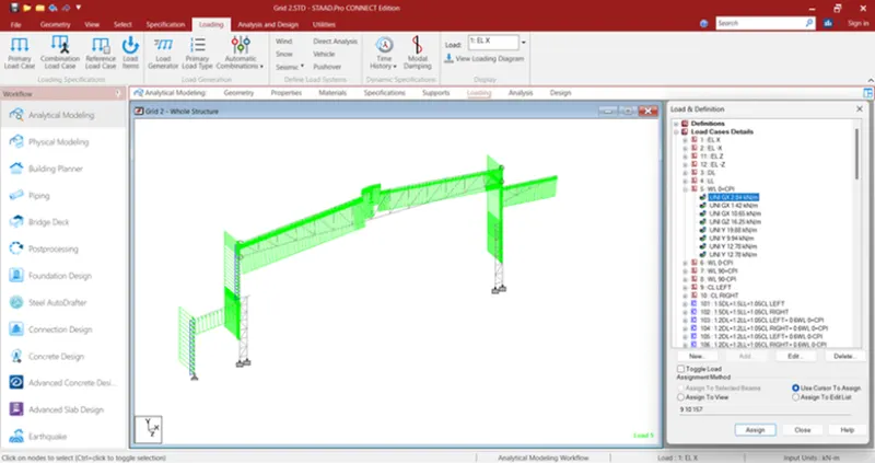
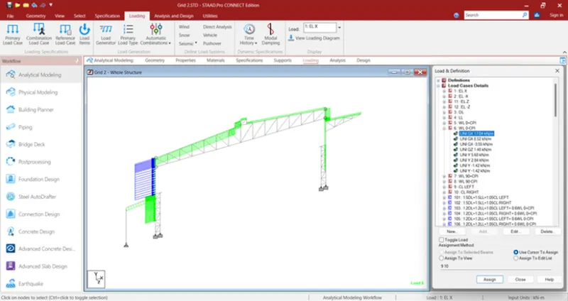
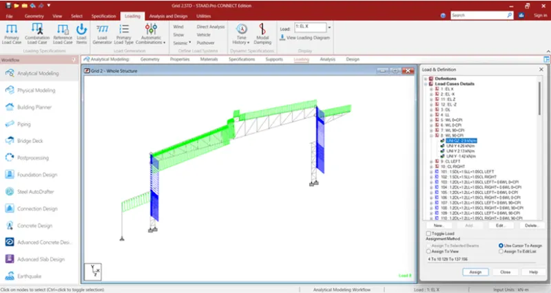
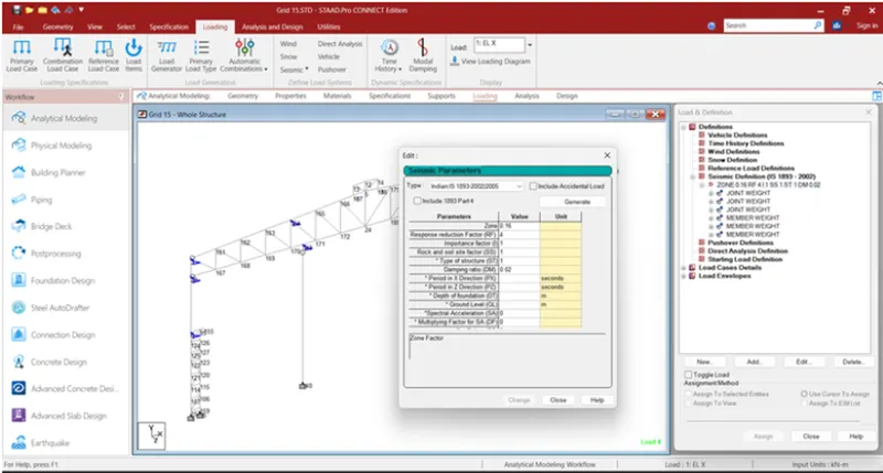
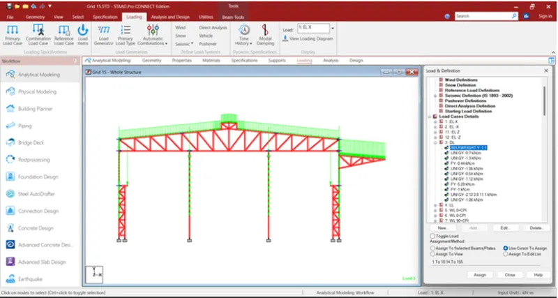
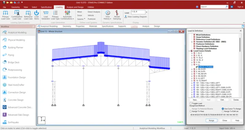
Select Loading Tab, add Earthquake, Dead load, Live load, Wind load, Crane load and Load Combinations as shown below.
Then Assign the above loads and load combinations to the members as shown below.
Step 7:-
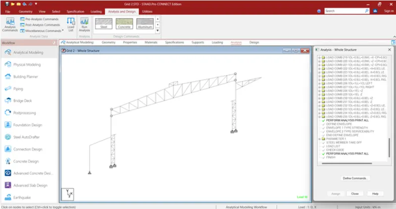
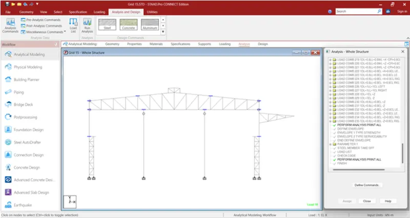
Now go to Analysis Tab, and click Define Commands.
Then create and assign Perform Analysis at each end of earthquake load and Final of commands.
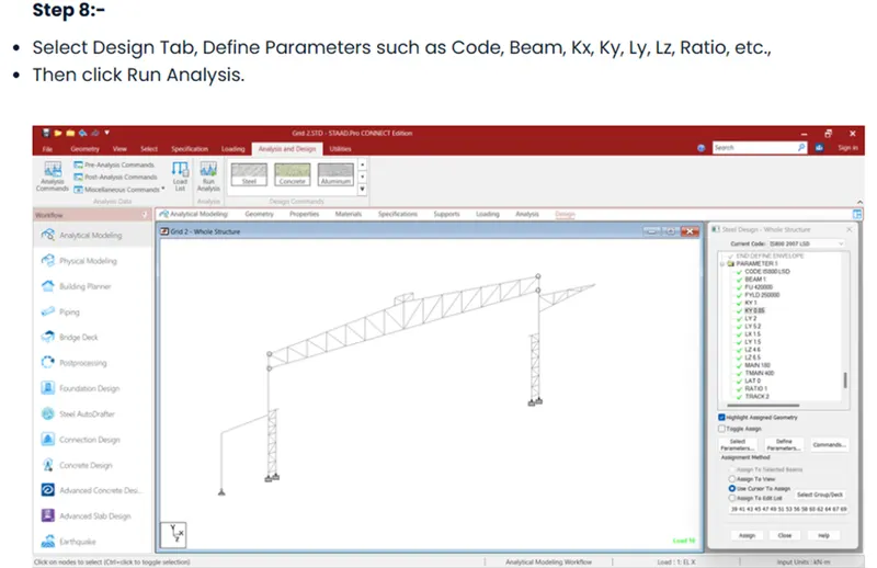
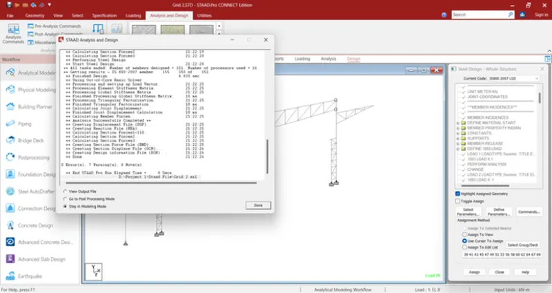
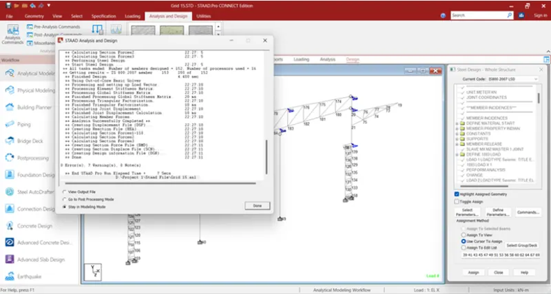
Output shows 0 error:-
Step 9:-
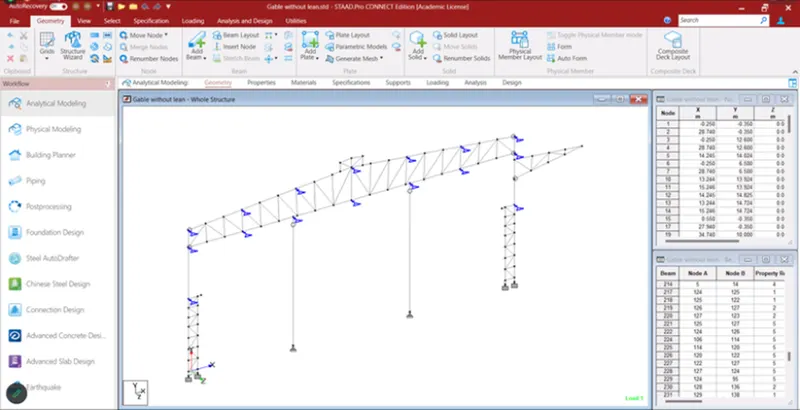
Similarly model and design the Gable Frame as did in Main Frame.
Only difference is Half of the loads only acts the Gable Frame.
Result:-
Model & Design a Proposed Coil Centre, Chennai using STAAD. Pro for following input from Client was done successfully.
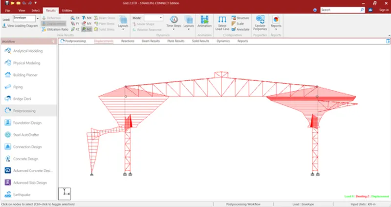
Bending Moment diagram for Main Frame (Grid 2).
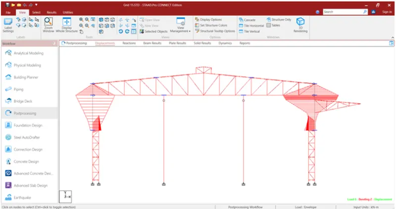
Bending Moment diagram for Gable Frame (Grid 15).