Project 1
1.Design the mainline alignment.
2.Create the existing ground profile of the above created alignment. Design the proposed profile for the mainline alignment.
3.Design alignments for remaining 4 intersecting streets (use mainline alignment CL to tie in).
4.Export the alignments, profiles to Land XML and save it in geometry folder.
*(Use appropriate curves, pay attention to tie-in conditions in plan and profile. Do check the snaps while building your geometry. Use appropriate feature definitions)
1.Design the mainline alignment.
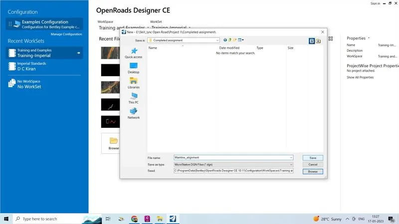
- To design alignment create a 2D seed file called mainline alignment
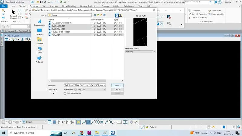
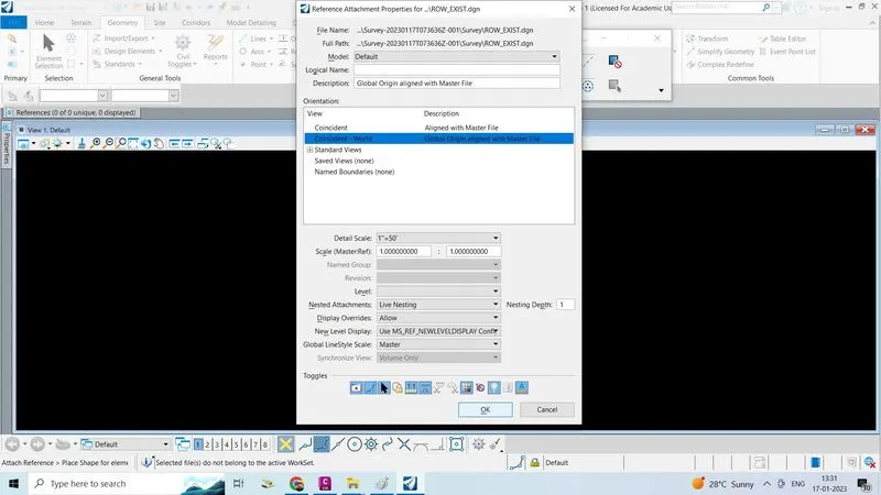
- Do design alignment we want some base called existing surface data, topo,ROW, survey file, click open
- Select model as defualt nested attachment as live nesting give nesting dept as 1 click ok
- Set the co-ordinate system now it is utilities tab
- Go to attributes set background map as aerial
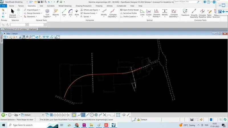
- Start desiging alignment select the element and copy the element and place it same position turn off the ROW topp for some time
- Select the copied element and go to properties change the class from primary to construction so that we can design alignment in green feild
- For joining or adding horizontal curves
- Go to geometry tab-->horizontal sections-->Click on arc select arc between -->Select simple arc
- Locate primary element and secondary element give radius right click horizontal curve is created
- Like wise do the same procedure for all horizontal curves
2.Create the existing ground profile of the above created alignment. Design the proposed profile for the mainline alignment.
- After creating alignment is created
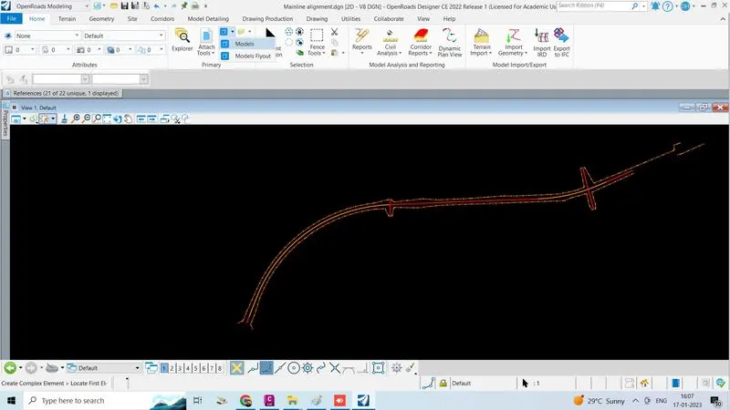
- Go to home tab, click on model select the defualt option and then
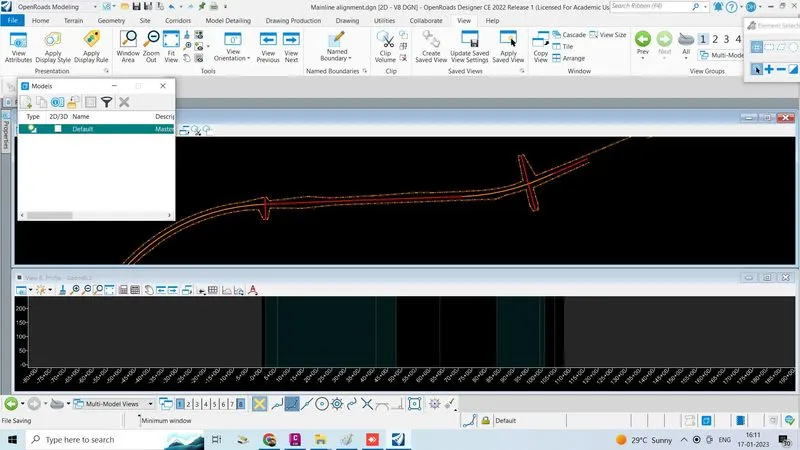
- Goto geometry, click on open profile model and locate plan element in one layout sheet locate sheet locate plane element in other layout sheet
- Now import the terrian {we want terrain for existing grade profile
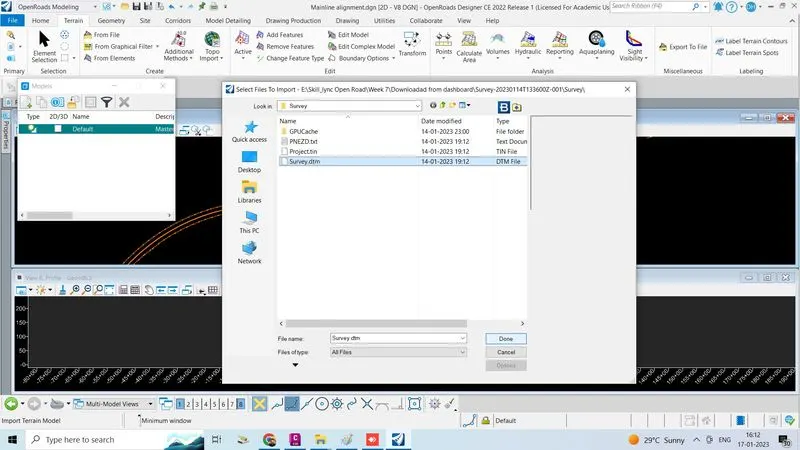
- Go to terrain tab, click on from file
- Select any type of formate like DTM, TIN,TXT
- Click on done
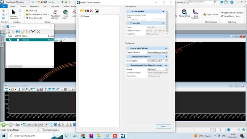
- Set feature defintion
- Set triangulation options as import terrain
- Set GCS click on import
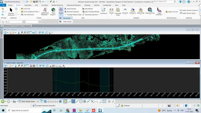
- Terrain is imported and select the terrain model activate the terrain
- Now want to draw proposed profile so
- Go to geometry tab in vertical selection
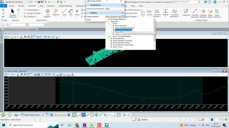
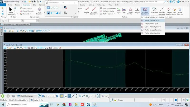
- In complex geometry select profile complex by PI and draw the vertical alignment
- Set the feature defintion and give the curve lenght and radius
- Proposed profile is created
3.Design alignments for remaining 4 intersecting streets (use mainline alignment CL to tie in).
- For design alignment for remaining 4 intersection streets
- Go to geometry tab
- Go to horizontal section
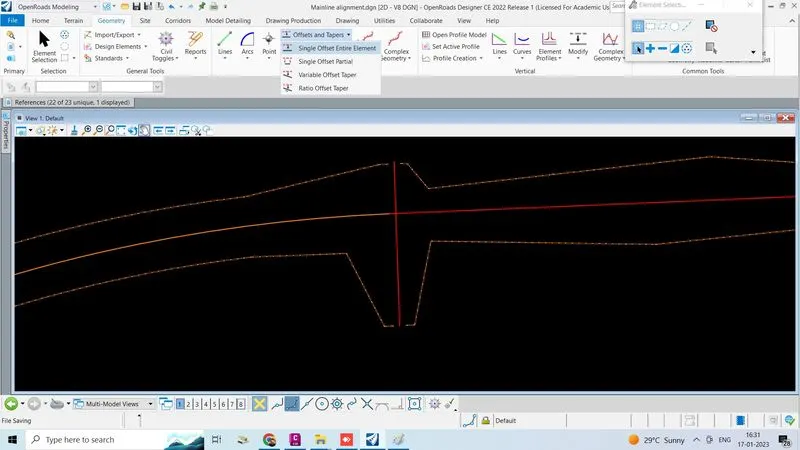
- Select line and draw in the intersection position and create offset alignment
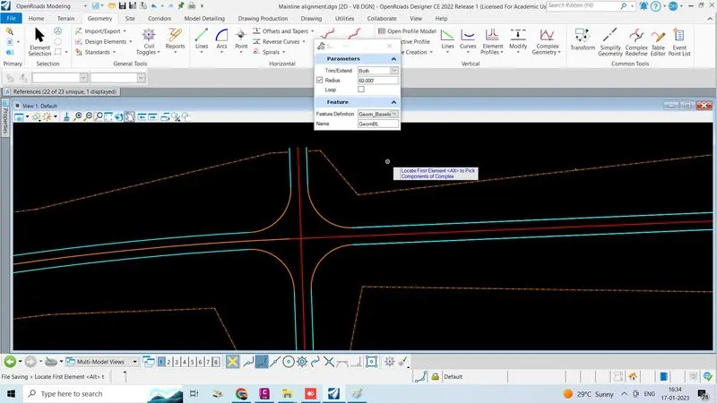
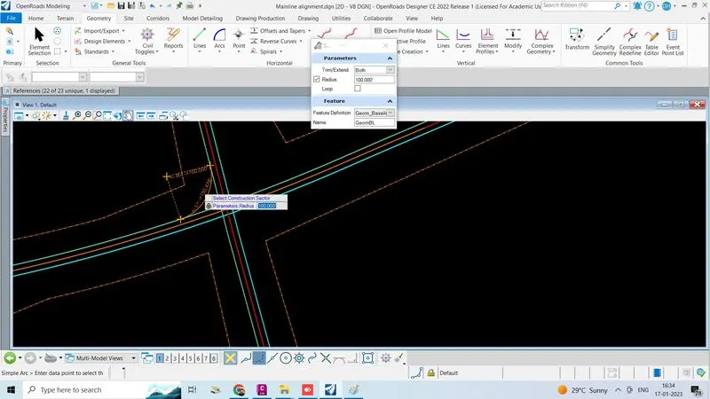
- Click on arc, select simple arc, locate 1st entity and 2nd entity and give the radius the intersection is created
- Repeate the same procedure for all intersection point
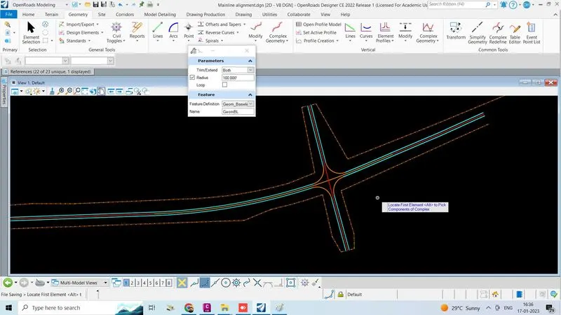
4.Export the alignments, profiles to Land XML and save it in geometry folder.
- For export or import into landxml
- Go to geometry tab
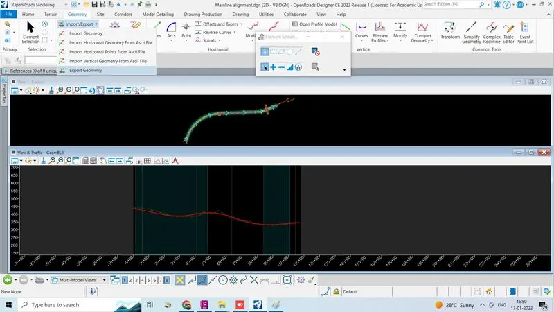
- In geometry tools section Click on import/export
- Click on export geometry
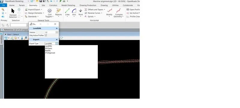
- Select export type as Landxml and right click
- Chose the landxml version 1.2
- For landxml only active profiles chose
- And save it in the proper folder click on save