Project 1
DOUBLE-ACTING ACTUATOR
Objective :
- Develop a double-acting actuator model using simscape multibody and simscape components.
- The Mechanical system of the cylinder needs to be built using simscape multibody library components.
- Hydraulic system needs to be modelled using simscape library physical components.
Introduction of Double-Acting Actuator :
Double acting hydraulic cylinder is also one type of hydraulic cylinder which is used for pulling, lifting, moving and holding the load. In a double acting cylinder, both chambers can be pressurized. Of the two chambers, the one that accommodates the cylinder rod will have little surface in contact with the hydraulic fluid, since we cannot take into account the surface area of the piston already occupied by the cylinder rod.
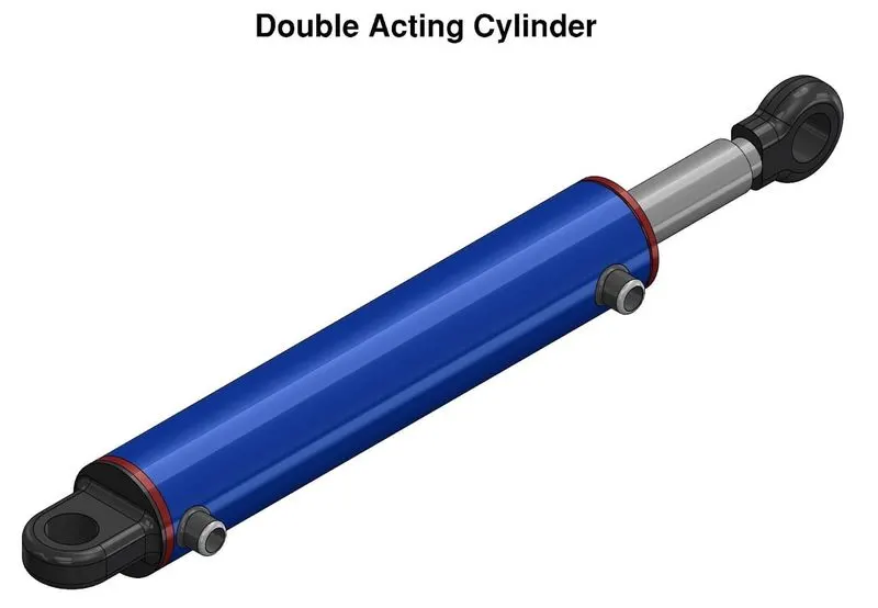
Cylinder Model
The following cylindrical model schematics show the cylinder three different configurations:
- Half-retracted
- Fully retracted
- And fully extended.
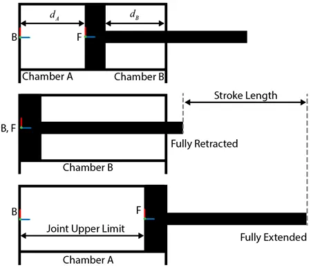
We can model the mechanical part of the system in Simscape Multibody. For example, to model the cylinder and piston, we can use the Revolved solid (Simscape Multibody) and Cylindrical solid (Simscape Multibody) blocks. To provide the translational degree of freedom for the piston, use a Prismatic joint (Simscape Multibody) block. To easily calculate the lengths of the chambers A and B, we can attach the base frame (B) and follower frame (F) of the joint to the centers of the left inner surface of the chamber A and the left surface of the piston, respectively. The Z-axes of the B and F frames are aligned and both point toward chamber B.
Using this convention, the length of the chamber A, dA, is the position output of the joint block, and the length of the chamber B, dB, equals the difference of the stroke length and dA. This is to ensure that the piston does not travel beyond the ends of the cylinder, we can specify the upper and lower position limits of the Prismatic Joint block.
Cylinder Model Explaination :
In chamber A, a pressure at port A moves the piston from 0 to stroke length. The displacement of the piston equals to the position output of the Prismatic Joint block. To model chamber A:
-
Connect the ports C and R of the Translational Multibody Interface block to the ports C and R of the upper Translational Mechanical Converter (IL) block, respectively.
-
In the Translational Mechanical Converter (IL) block, set Interface displacement to provide input signal from multibody joint to enable port P.
-
Connect ports P of the Prismatic Joint block and Translational Mechanical Converter (IL) block.
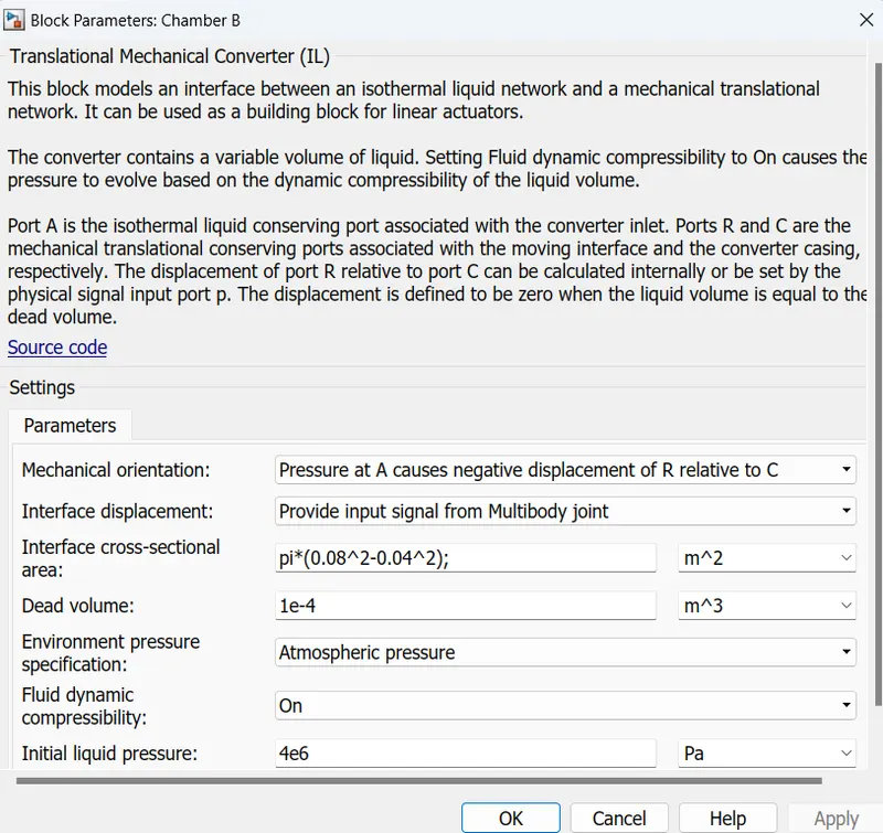
In chamber B, the pressure at port A moves the piston from 0 to negative stroke length. Therefore, you need to change the default orientation and add an offset to the input position signal of the lower Translational Mechanical Converter (IL) block. The offset equals -dB.
-
In the lower Translational Mechanical Converter (IL) block, set Mechanical orientation to pressure at A couses negative displacement of R relative to C.
-
Set Interface displacement to provide input signal from multibody joint to enable the port P.
-
Add a PS-contant block and specify the constant as the stroke length of the cylinder.
-
Add a PS-substract block, then connect it to the PS Constant and Prismatic Joint blocks as shown in the diagram. Note that the output of the PS Subtract block equals -dB.
To limit the travel of the piston:
-
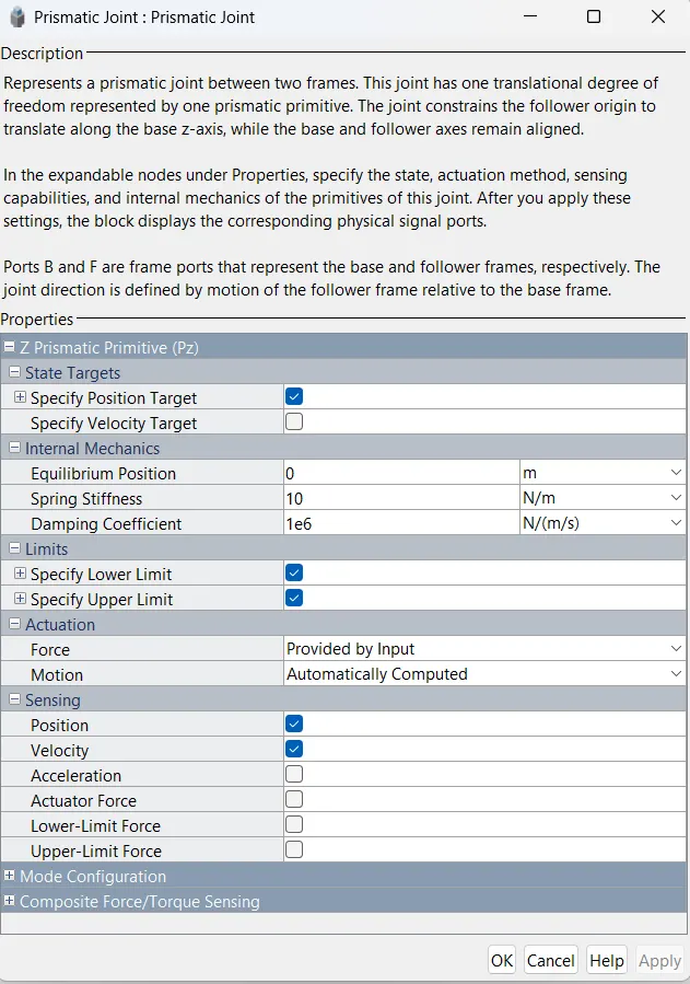
In the Prismatic Joint block, under the Limits section, select the Specify Lower Limit and Specify Upper Limit parameters.
-
Under the Specify Lower Limit section, the Bound parameter indicates the minimum distance between the frames B and F of the joint block. In this example, specify the Bound parameter as 0 m.
-
Under Specify Upper Limit, the Bound parameter indicates the maximum distance between frames B and F of the Prismatic Joint block. In this example, specify the Bound parameter as the stroke length of the cylinder.
How does the Double-Acting Cylinder work
Double acting hydraulic cylinder will have one piston within a cylindrical housing. When hydraulic oil will be supplied to its cap end port, hydraulic pressure force will be applied over the piston or plunger and hence piston will be extended and this stroke of cylinder will be termed as forward stroke. During extension of the cylinder piston or plunger, hydraulic oil at rod end side will be pushed out and will be directed towards reservoir.
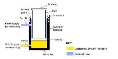
Double-Acting hydraulic cylinder
For return stroke or retraction of cylinder, hydraulic fluid direction will be reversed with the help of direction control valve. During return stroke, hydraulic oil will be supplied to its rod end port and therefore hydraulic pressure force will be applied over the piston or plunger from rod end side and hence piston will be retracted and this stroke of cylinder will be termed as return stroke. During retraction of the cylinder piston or plunger, hydraulic oil at cap end side will be pushed out and will be directed towards reservoir.
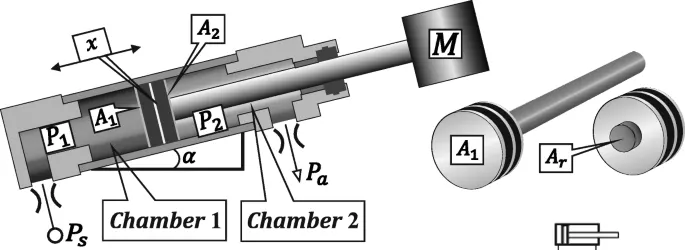
Working of double acting hydraulic cylinder
Simscape Model :
This model shows the block diagram of the double-acting actuator model in Simscape library. The model uses two Translational Mechanical Converter (IL) blocks to model the chambers A and B of the cylinder. A Translational Multibody Interface block connects the Translational Mechanical Converter (IL) blocks to the Prismatic Joint block. See Connecting Simscape Network to Simulink Multibody Joints for details of how to use the Translational Multibody Interface block.
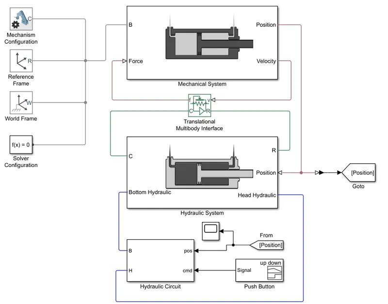
- Subsytem of Mechanical System :
Mechanical System
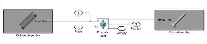
Cylinder Assembly
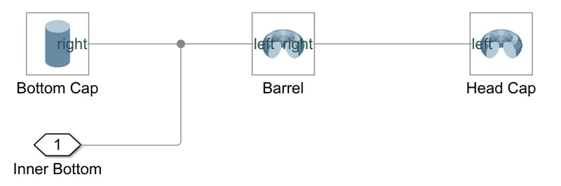
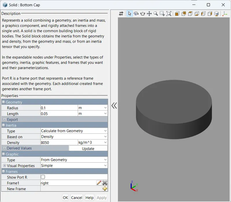
Parameter taken in cylindrical assembly
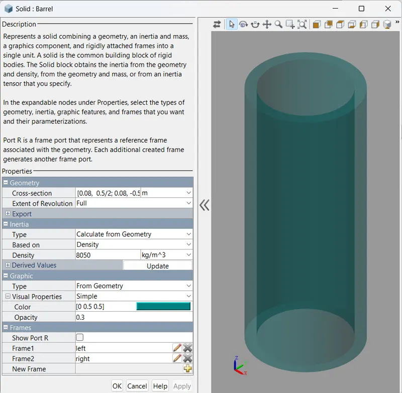
Bottom Cap : Barrel :
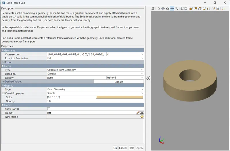
Head Cap :
Prismatic Joint :
Piston Assembly :
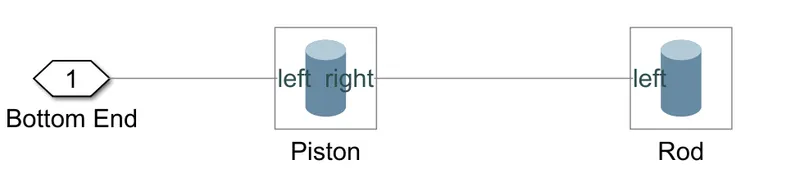
Parameter taken in Piston assembly
Piston : Rod :
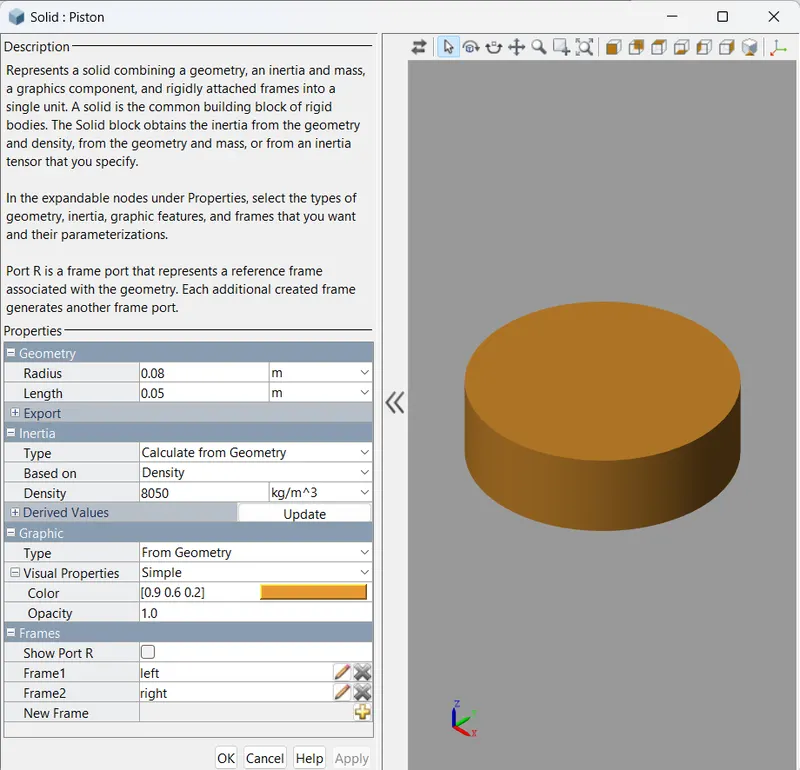
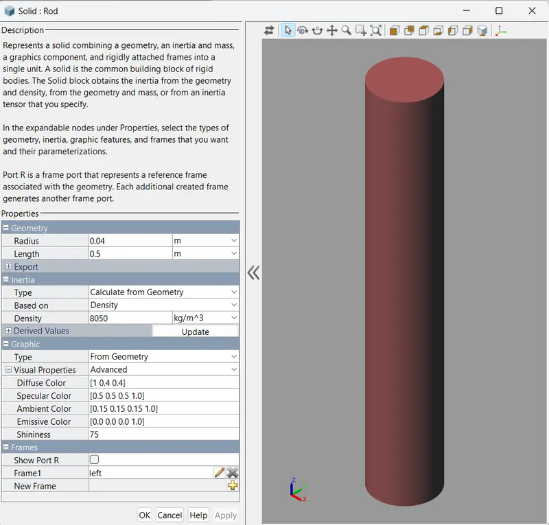
- Subsytem of Hydraulic System :
Hydraulic System :
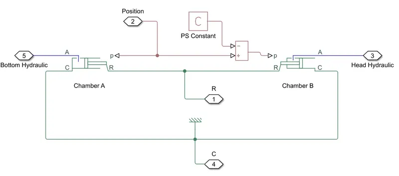
Chamber A : Chamber B :
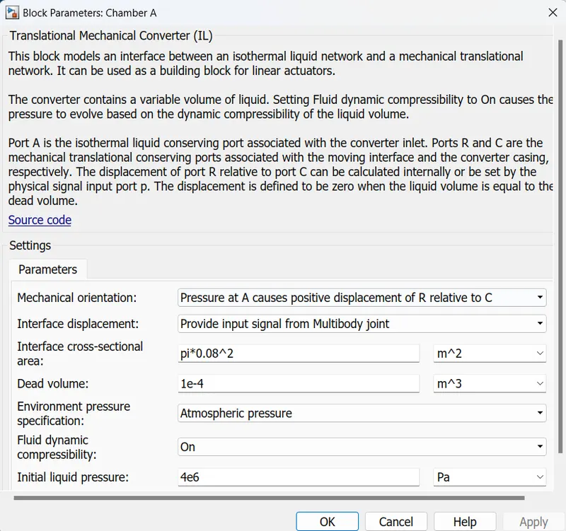
PS Constant : 0.45 m
- Subsystem of Hydraulic Circuit :
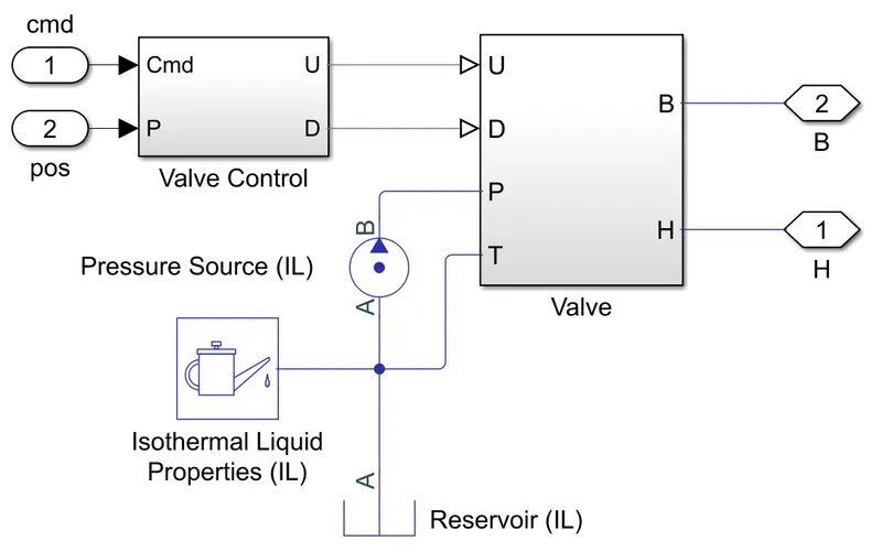
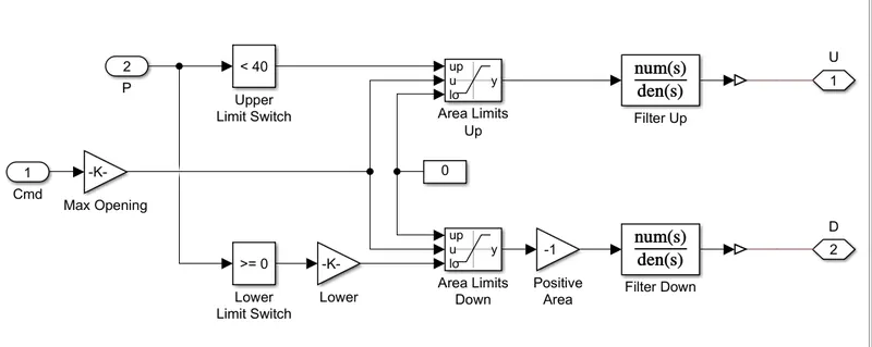
Valve :
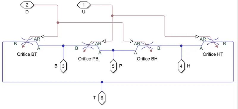
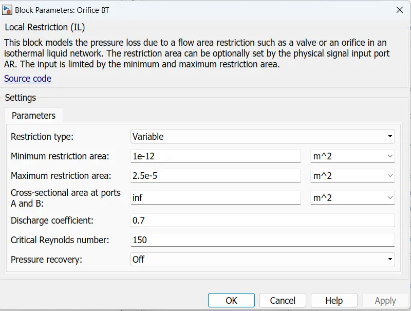
Parameter taken for the model in different orifice
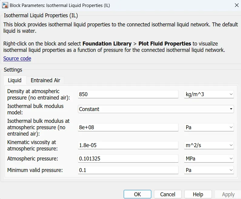
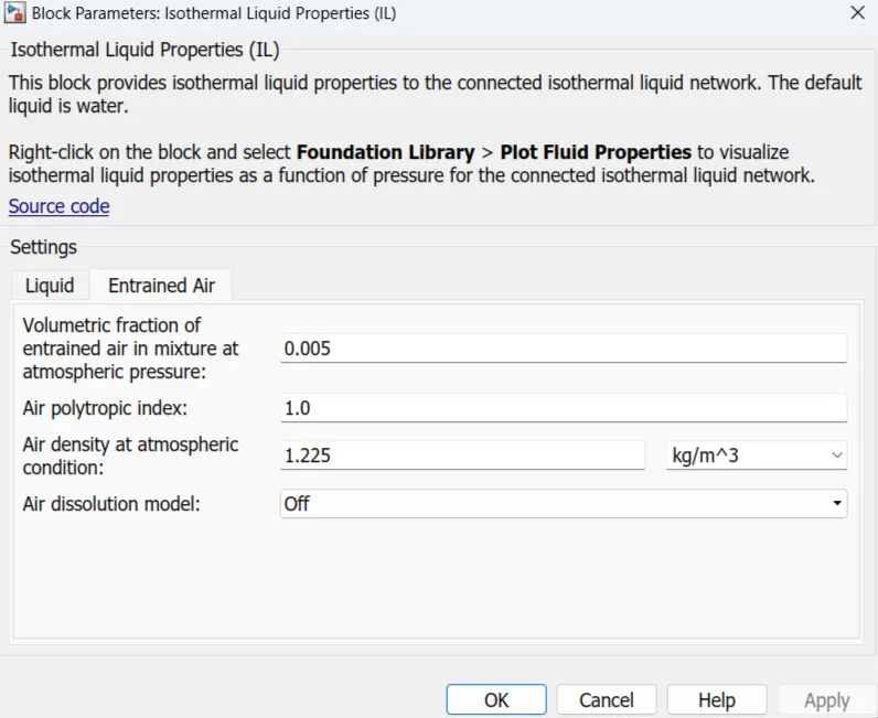
Isothermal Liquid Property :
Isothermal liquid domain, the working fluid is a mixture of liquid and a small amount of entrained air. Entrained air is the relative amount of non-dissolved gas trapped in the fluid. we can control the liquid and air properties separately : here we can specify zero amount of entrained air.
Orifice BT,PB,BH and HT
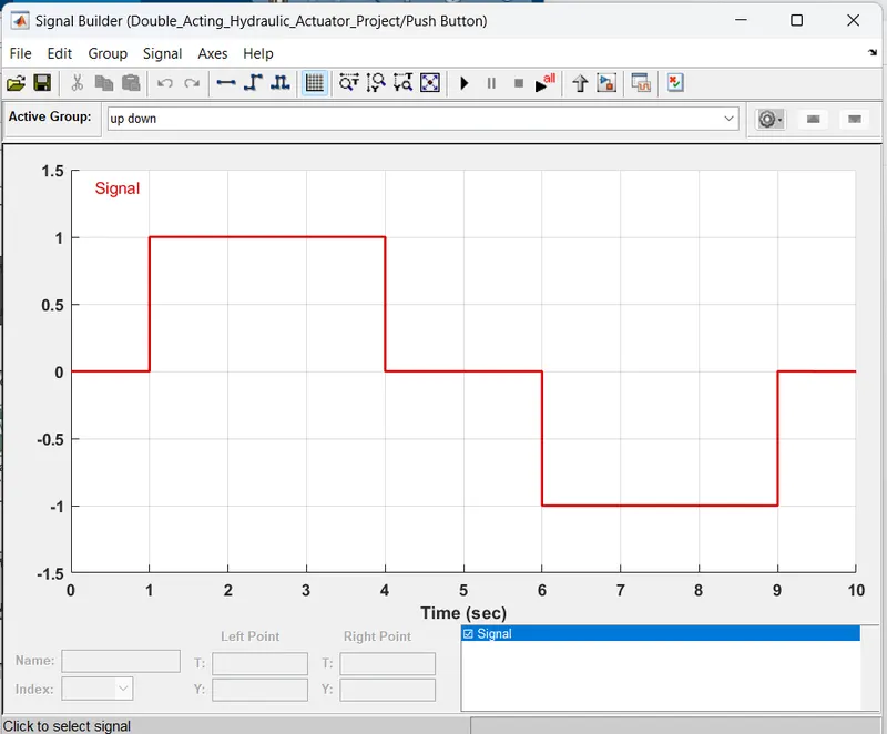
- Push Buttom (signal builder) :
Results :
The Double-Acting actuator model shown below.
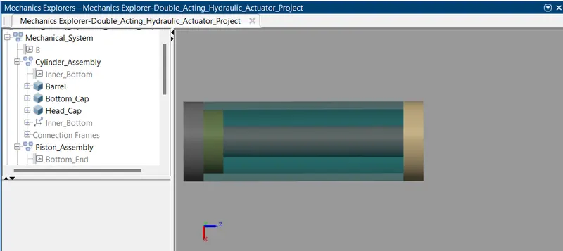
- Initial condition : Initailly Double-Acting actuator is rest when no load is applied.
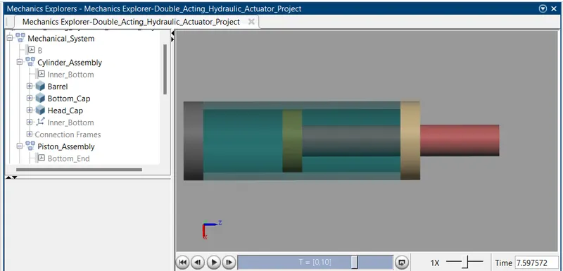
- Half-retracted : When hydraulic oil will be supplied to its cap end port, hydraulic pressure will be applied over the piston or plunger and hence piston will be extended and this stroke of the cylinder will be termed as forward stroke. During extension of the cylinder piston or plunger, hydraulic oil at rod end side will be pushed out and will be diredted towards reservoir.
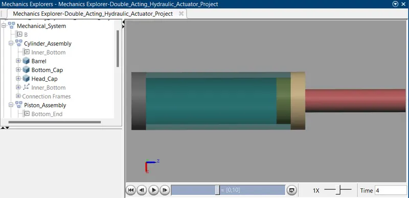
- Return Stroke : During return stroke, hydraulic oil will be supplied to its rod end port and therefore hydraulic pressure force will be applied over the piston or plunger from rod end side and hence piston will be retracted and this stroke of cylinder will be termed as return stroke. During retraction of the cylinder piston or plunger, hydraulic oil at cap end side will be pushed out and will be directed towards reservoir.
Conclusion :
We develop a double-acting actuator model using Simscape multibody which is used for pulling, lifting, moving and holding the load.