Project 1
Aim:
1) Mention the need for a metro rail in a developing economy.
- 'Metro Rail' is a commuter-friendly transport providing the traveling public with c a fast, safer, reliable, comfortable, pollution-free, affordable, convenient, and eco-friendly service. The high-capacity Metro Rail System would reduce the ever-increasing traffic congestion on the city roads.
- The most efficient transportation system is space occupancy, energy consumption, and numbers transported.
- They are very high-capacity carriers, transporting many people during peak hours.
- Unlike buses and other modes of public transportation, metro rails are eco-friendly, cause much less sound pollution, and have no air pollution.
- They possess greater traffic capacity. It carries as much traffic as seven lanes of bus traffic and 24 lanes of car traffic.
- It reduces the journey time from 50% to 75%.
- The usage of metros should be promoted more and more as it helps in reducing the levels of greenhouse gases.
- The number of road accidents has also gone down drastically as people have chosen the Metro. Speeding usually happens when people are late for their work.
- Metro provides air-conditioned traveling with the best comfort at relatively cheap rates
2) Perform longitudinal analysis of 3 x 25m prestressed I-girder for metro viaduct in STAAD by creating the nodes, beams, and supports being assigned to those nodes for a slab and girder that has been presented in the videos.
--> Procedure:
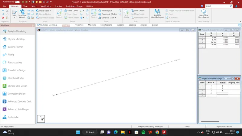
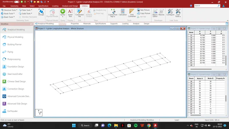
Step 1: Creating Grid Modeling in STAAD.Pro
Creating node (0,0,0) -> Selecting Node using node cursor -> Copy it in X direction using Translation repeat option
Connect both the node -> Geometry -> Add beam
- According to the suitable size create a Girl model
Step 2:
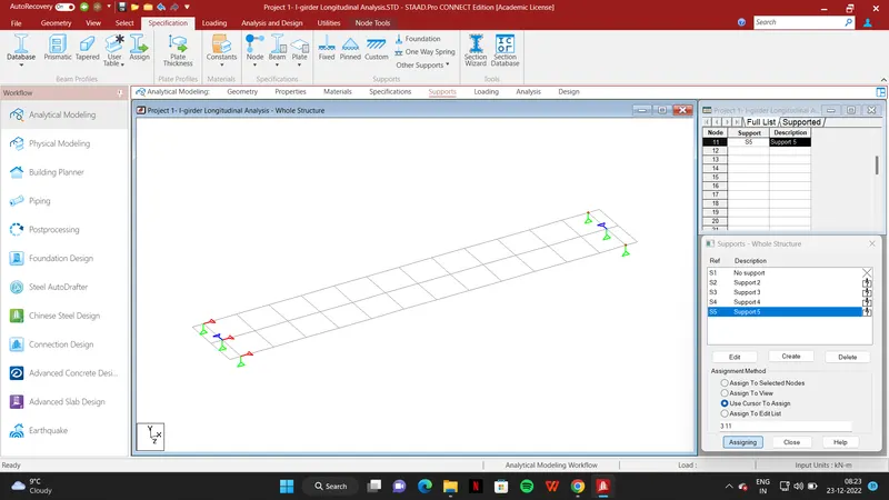
Assigning Support
Specification -> Support -> Create -> Fix but -> Release ( MX, MY, MZ ) -> Add -> Select support 2 -> Select node -> Assign to selected nodes -> Assign
Specification -> Support -> Create -> Fix but -> Release ( FX, MX, MY, MZ ) -> Add -> Select support 3 -> Select node -> Assign to selected nodes -> Assign
Specification -> Support -> Create -> Fix but -> Release ( FZ, MX, MY, MZ ) -> Add -> Select support 4 -> Select node -> Assign to selected nodes -> Assign
Specification -> Support -> Create -> Fix but -> Release ( FX, FZ, MX, MY, MZ ) -> Add -> Select support 5 -> Select node -> Assign to selected nodes -> Assign
- Select a node according to suitable support and assign to it
Step 3:Assign Property to Model
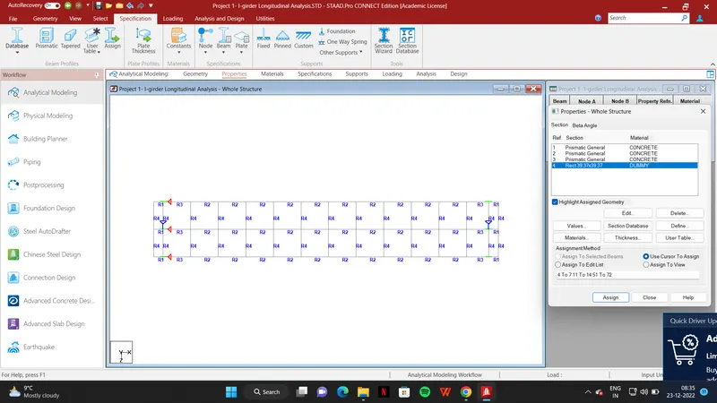
Specification -> Property -> Define -> General -> Insert the value Cross-section dimension of beam -> Add -> Select the property -> Select the beam -> Assign to selected beam -> Assign
Step 4: Applying Loading on Model
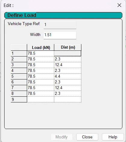
I. Vehicle Definition
Loading -> Load & Definition -> Definitions -> Vehicle Definition -> Add
II. Dead Load.
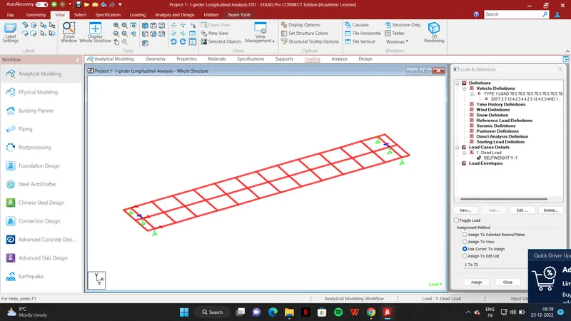
Loading -> Load & Defination -> Load Case Detail -> Title ( Dead Load ) -> Add -> Select Dead Load -> Add -> Self Weight Factor -1 -> Add -> Select Selfweight - 1 -> Assign to view -> Assign.
III. SIDL
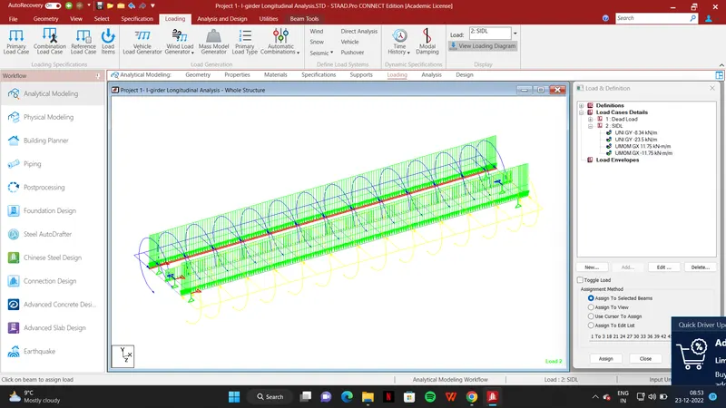
Loading -> Load & Definition -> Load Case Detail -> Title ( SIDL ) -> Add -> Select SIDL -> Add -> Member Load -> Uniform Force -> W1 -8.34 Direction GY-> Add -> Select Load -> Select Suitable beam Beam -> Assign to selected beam -> Assign
- Repeat the same procedure for different beams according to suitable force.
IV. Load Generation
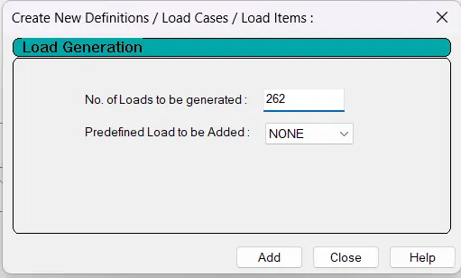
Loading -> Load & Definition -> Load Case Detail -> Add -> Load Genaration -> No of load to be generated -> Add -> Generted Load -> Position of coordinate -> Add
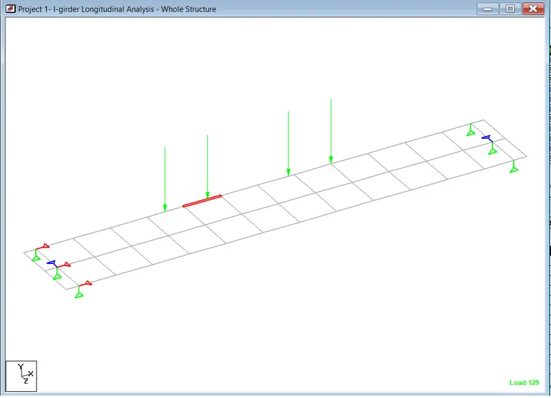
Step 5: Analysis and Results
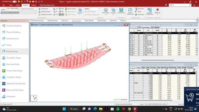
Analysis And Design -> Analysis Commands -> Run Analysis -> Go to post prossing mode -> Done
Result Extraction:
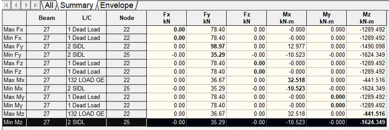
For Dead Load:
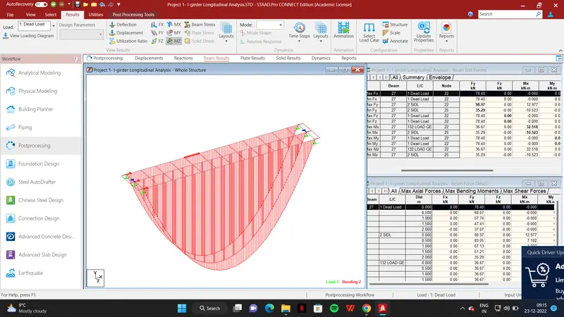
For SIDL:
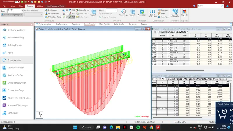
For Moving Load:
3) Prepare a transverse STAAD model of U-girder with the following specifications:
- Finite element model of U-girder with a span length of 30m.
- Having supports at 0.7m from both ends.
- Having the following geometrical properties:
- Thickness of bottom slab – 300mm
- Thickness of top web (both sides) – 240mm
- Thickness of slant web - varying from 300mm to 240mm
- Concrete grade M55.
Reference inputs can be taken from the relevant video sessions if needed.
--> Step 1: Creating Grid Modeling in STAAD.Pro
- Arranging the node in the shape of U Grider
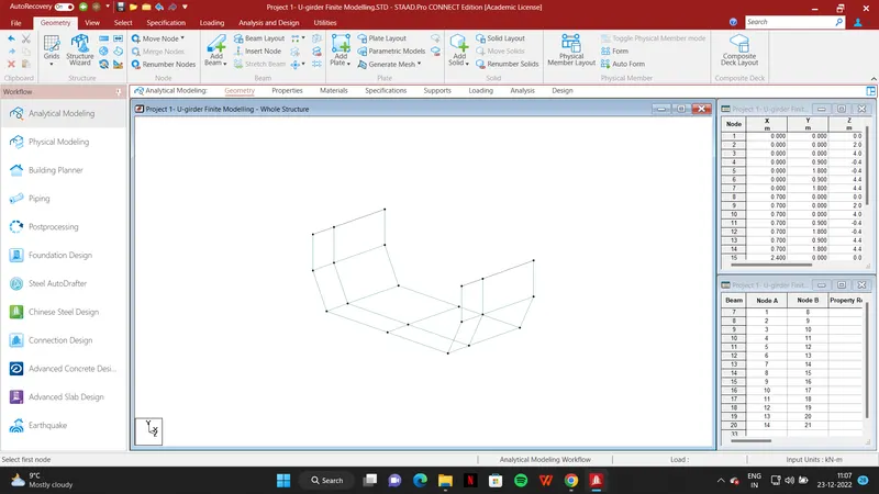
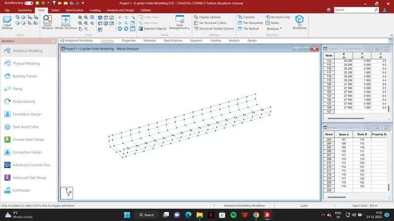
- Making Full U Girder model using translation repeat option
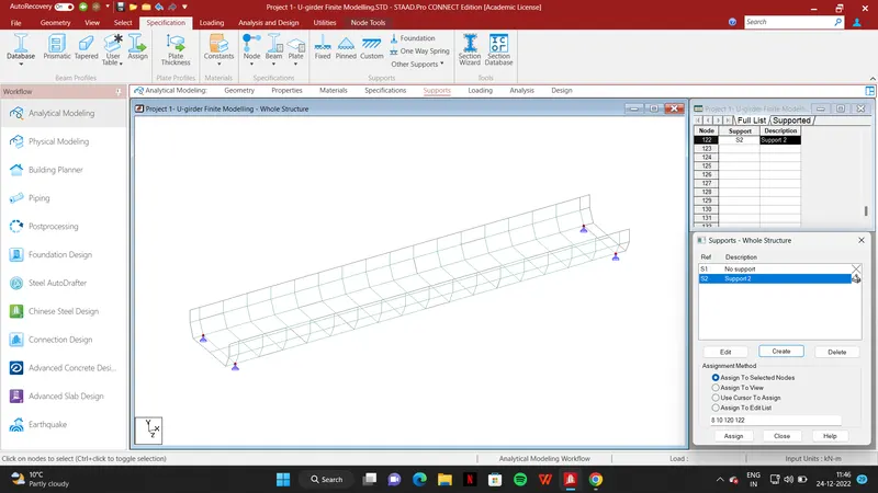
Step 2: Assigning Pinned Supports
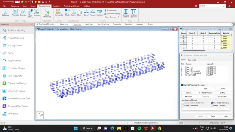
Step 3: Assign Property to Model
For Plate
Specification -> Property -> Thickness -> (Insert Plate thickness size) -> Add -> Select Plate -> assign
- Repeat the same procedure for different plates & also assess thickness in variable conditions.
For Beam
Specification -> Property -> Define -> Rectangular -> Size 0.01 x 0.01 material as DUMMY -> Select beam -> Assign to selected beam -> Assign
Step 4: Applying Loading on Model
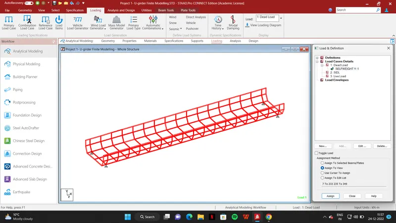
I. Dead Load.
Loading -> Load & Defination -> Load Case Detail -> Tital ( Dead Load ) -> Add -> Select Dead Load -> Add -> Self Weight Factor -1 -> Add -> Select Selfweight - 1 -> Assign to view -> Assign.
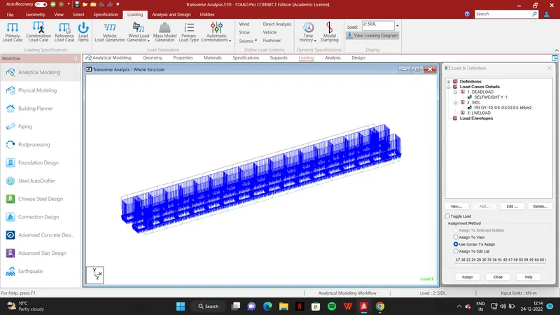
II. SIDL
Loading -> Load & Definition -> Load Case Detail -> Title ( SIDL ) -> Add -> Select SIDL -> Add -> Plate Load -> Partial Plate Pressure -> W1=-10 , X1= -0.8 , X2=0.8 , Y1=-0.5 , Y2=0.5 , Direction GY-> Add -> Select Load -> Select all bottom plate -> Assign to selected plate -> Assign
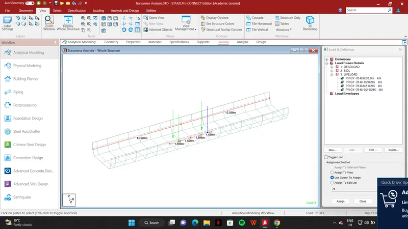
III. Live Load
Loading -> Load & Definition -> Load Case Detail -> Title ( Live Load ) -> Add -> Select Live -> Add -> Plate Load -> Concentrated Load -> W1=-78 , X= 0.2 , Y=0.245 , Direction GY-> Add -> Select Load -> Select Suitable plate -> Assign to selected plate -> Assign
- For Other Plate repeat the same procedure and change the value of X, Y
IV. Combination Of SLS & ULS
Loading -> Load & Definition -> Load Case Detail -> Add -> Define Combination -> Select load and inser the factor according to given in IRS CBC -> Add -> Close
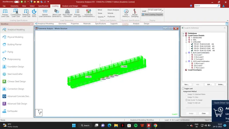
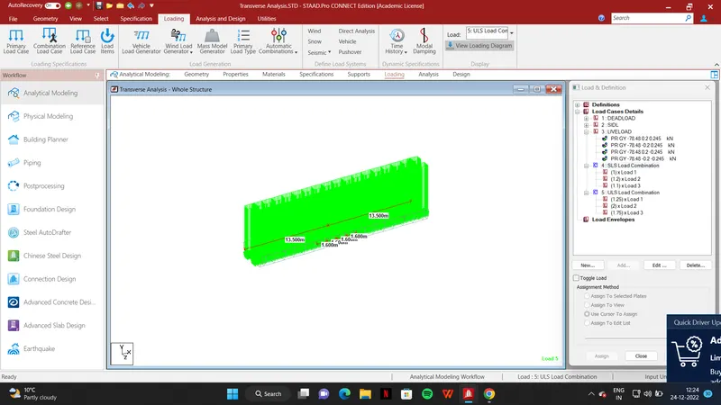
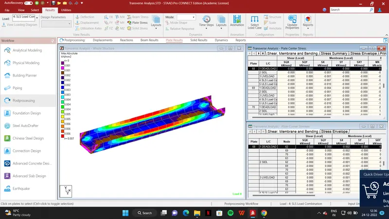
Step 5: Analysis And Result
Analysis And Design -> Analysis Commands -> Run Analysis -> Go to post prossing mode -> Done
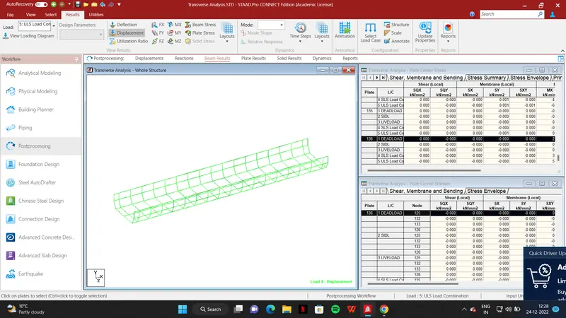
Maxm. MY in SLS Combination
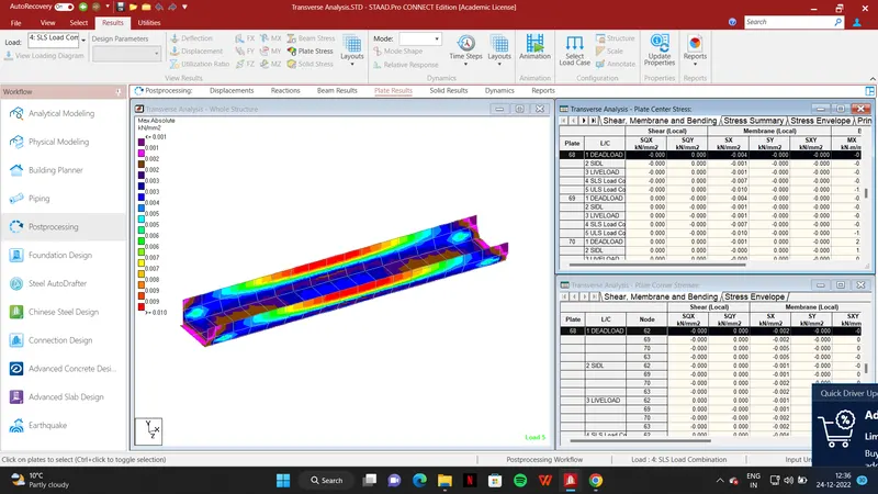
Maxm. MY in ULS Combination
4) For a prestressed U girder, calculate the following with the given data,
Given Data:
- Area = 2.1735m2
- I = 0.74035m4
- Calculate Prestressing force considering 76.5% jacking stress with 72 no. of strands.
- Calculate Section Modulus of U-girder considering ybot = 0.594m
- Calculate eccentricity of Prestress tendons from CG of section considering ybot = 0.594m and cg of PT cables = 0.140m from soffit level.
- Calculate Stress at bottom of U-girder considering M=10628.58kN-m and details mentioned previously.
Assumption data of characteristics of prestressing steel:
- Nominal area of strand:As = 140 mm2
- Nominal ultimate stress: fpu = 1860 Mpa
- Maxm. jacking stress : 0.765 fpu = 1422.9 Mpa
- Modulus of elasticity : Ep= 195000 Mpa
--> i) Calculate Prestressing force
Soln: No. of strand used (n) = 72
Prestressing force applied (P)
= ( 0.765fpu x As x n X (1-Loss)) / 1000 kn
= (1422.9 x 140 x 72 x 76.5) / 1000 kn
= 10972.2 kN
ii) Calculating section modulus (Z) = I/y
Soln: For Checking stress at bottom, ybot = 0.594m
Z= 0.74035/0.594
= 1.2464 m3
iii) Calculate eccentricity of Prestress tendons from CG of section
Soln: CG of the section to CG of tendons (e)
= 0.594 - 0.140 m
= 0.454 m
iv) Calculate Stress at bottom of the U-girder
Soln: Stress @ bottom
= P/A + P x e/Z - M/Z
= 10972.2/2.1735 + 10972.2 x 0.454 / 1.2454 - 10628.58/ 1.2464
= 0.517 N/mm2