Project 1
ENGINE WIRING HARNESS CREATION:
1. Context Assembly:
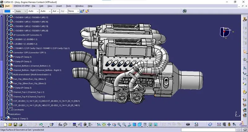
Create a product file as a context assembly and name it "Assy. Engine Harness Context".
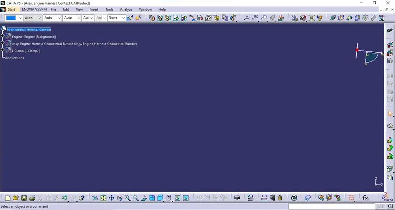
2. Import Background:
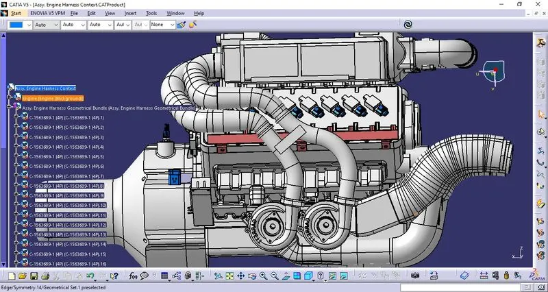
The CAD file of the Engine is provided as background for the wiring harness. Import the engine CAD file into the context assembly.
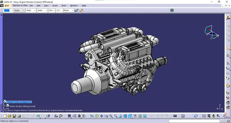
3. Create Engine Harness Geometrical Bundle:
A product file is created into the context assembly as Geometrical Bundle and named "Assy. Engine Harness Geometrical Bundle".
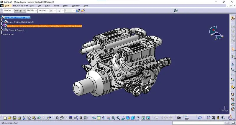
i. Define Connectors Electrically:
Define all the required connectors electrically.
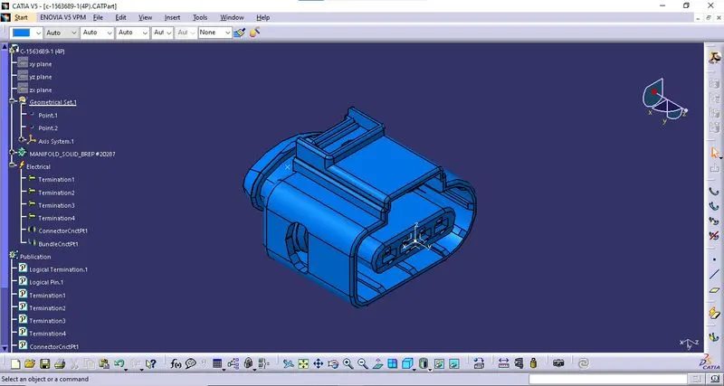
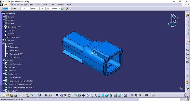
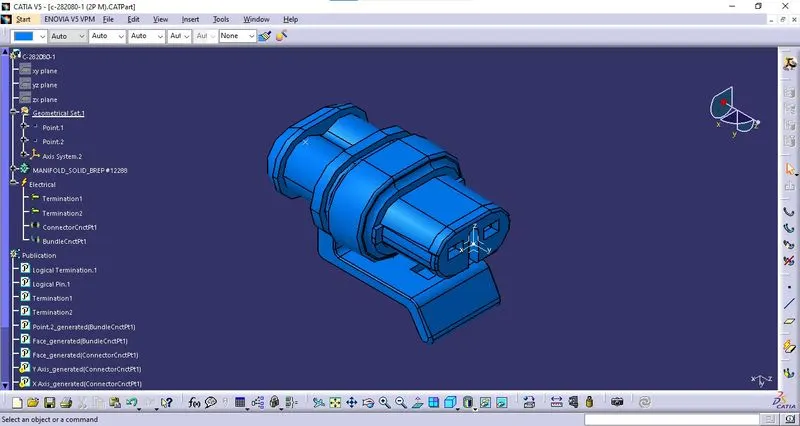
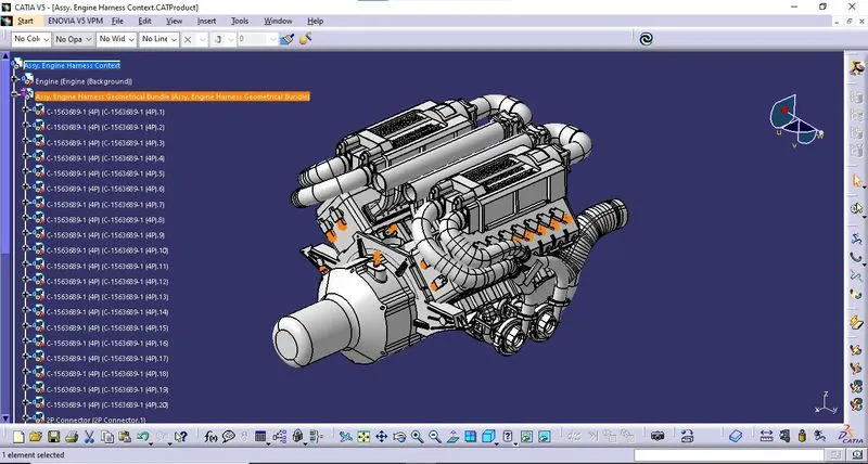
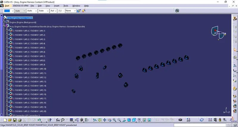
ii. Import & Locate Connectors:
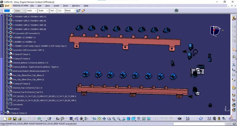
All the connectors that are required for the connections are imported into the geometrical bundle and placed at the required locations.
iii. Inter Connector:
An Interconnector is used to separate the engine harness from the main harness bundle.
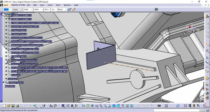
a. L Bracket:
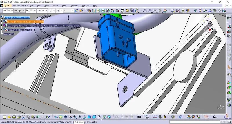
For the positioning of the interconnector, the L bracket was added to the engine block.
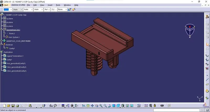
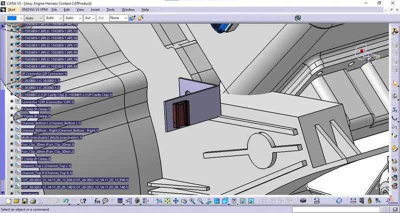
b. Cavity Clip:
A cavity clip was electrically defined and placed over the L Clamp.
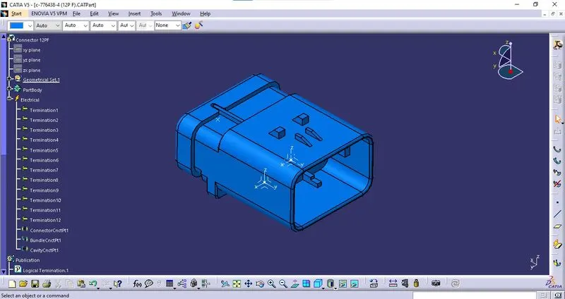
c. Inter Connector:
A 12-pole connector was chosen as an interconnector. It is electrically defined and positioned using the cavity clip.
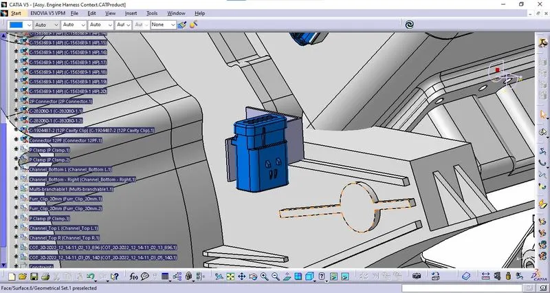
iv. Clamps & Clips:
The Clamps & Clips are electrically defined as the support equipment.
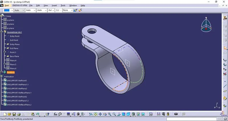
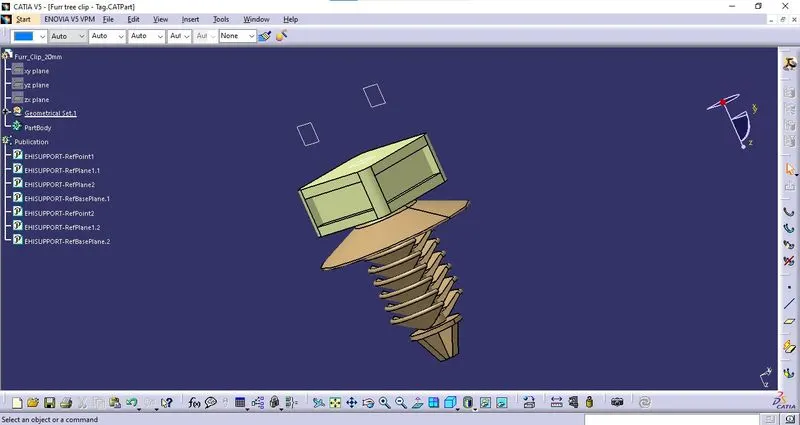
Thus defined clamps & clips are placed into the Geometrical bundle at the required positions to route the harness.
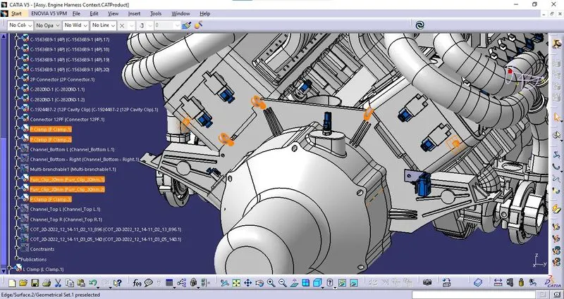
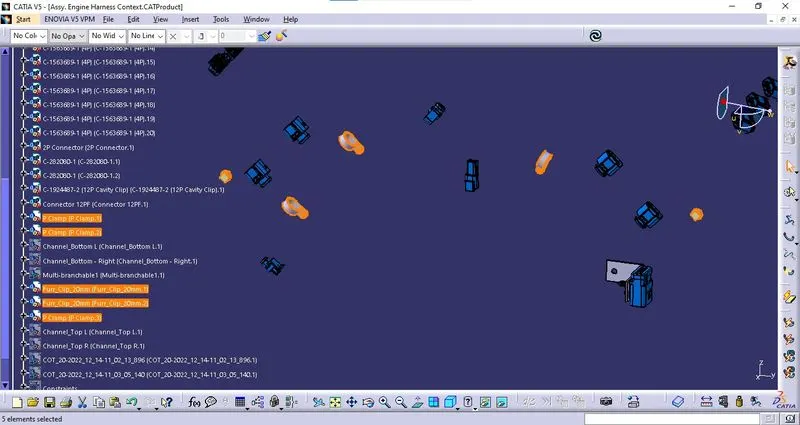
v. Channel:
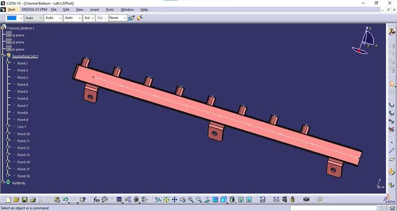
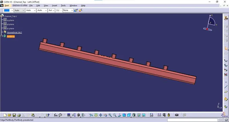
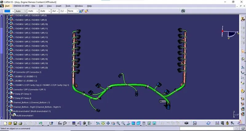
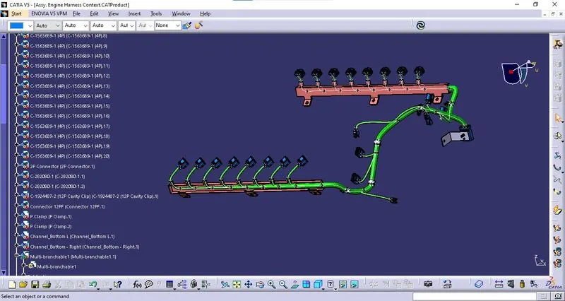
A Channel was created for the connectors present at the left and right blocks of the Engine. This is created to guide the wires and protect them from heat.
The thus created channel is electrically defined and points were created for routing of the harness.
a. Channel - Left:
b. Channel - Right:
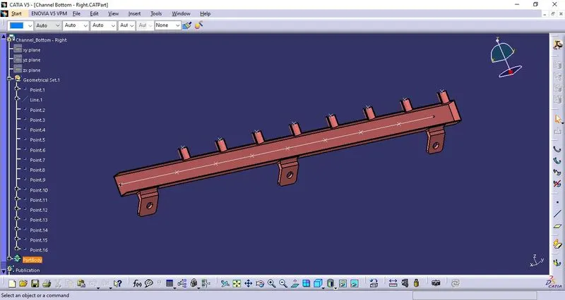
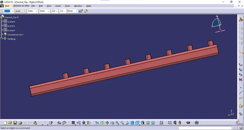
Bottom channels are imported into the geometrical bundle assembly.
vi. Creating Wiring Bundle:
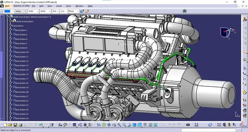
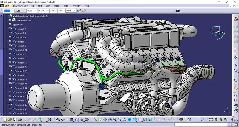
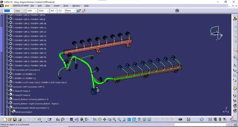
Create a wiring bundle from the interconnector to the various connectors with the appropriate routing and bundle diameter size. Multiple branching points were taken for appropriate routing and positioning. Required slacks were provided in a few bundles.
vii. Protective Covering:
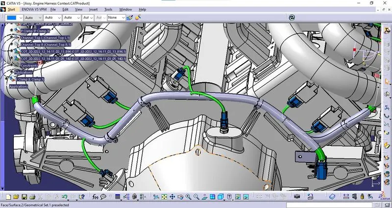
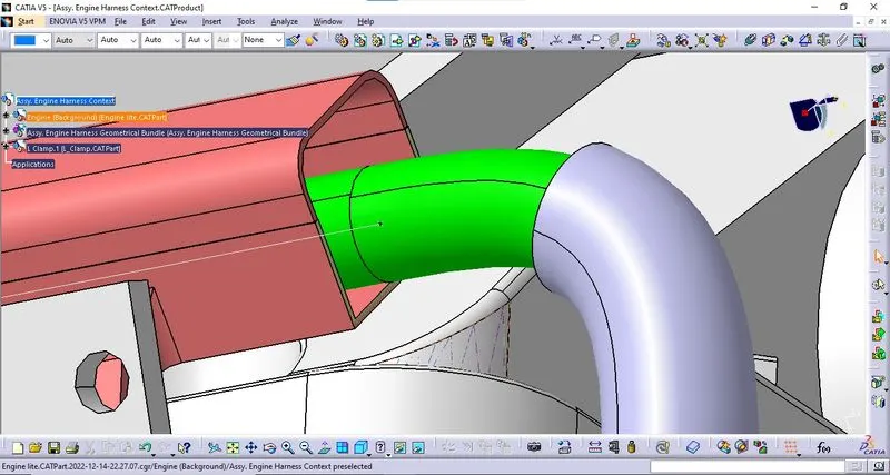
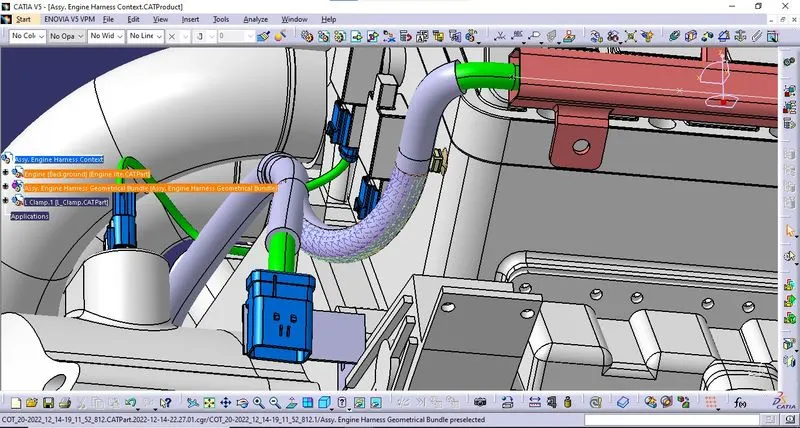
At places where the harness might be exposed to heat from the engine, corrugated tubes of appropriate size are used as protective covering.
viii. Channel Lid:
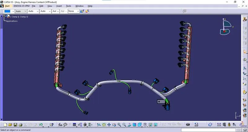
the channels provided were covered with their counterparts to ensure that the harness stays within the channel.
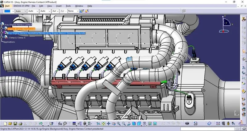
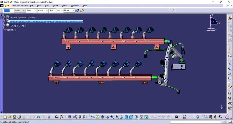
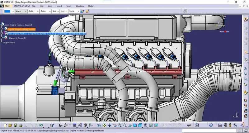
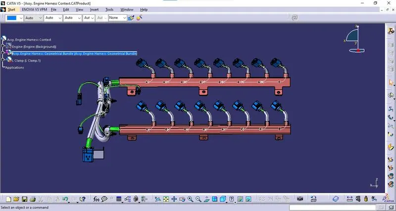
Thus the engine wiring harness is successfully routed with the application of all Packaging rules and Industry best practices.
4. Flattening of Harness:
i. Create a product:
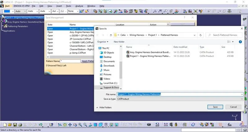
Create a product file and name it as "Project 1 - Engine Wiring Harness Flatterning"
ii. Defining Flattening Parameters:
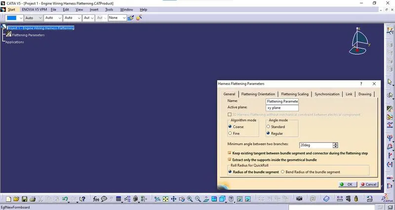
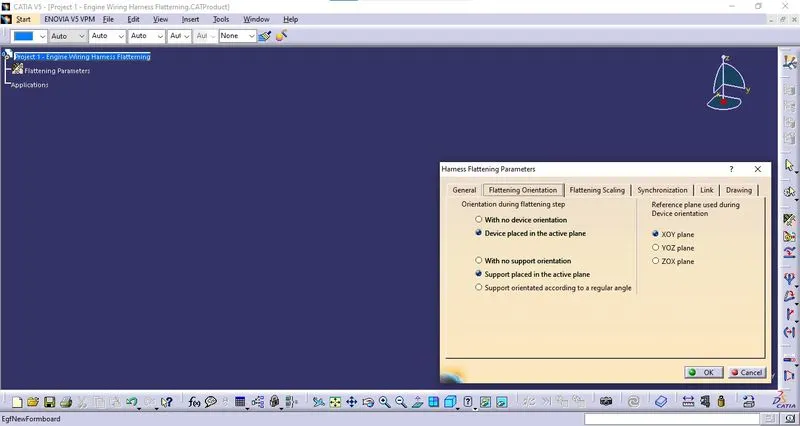
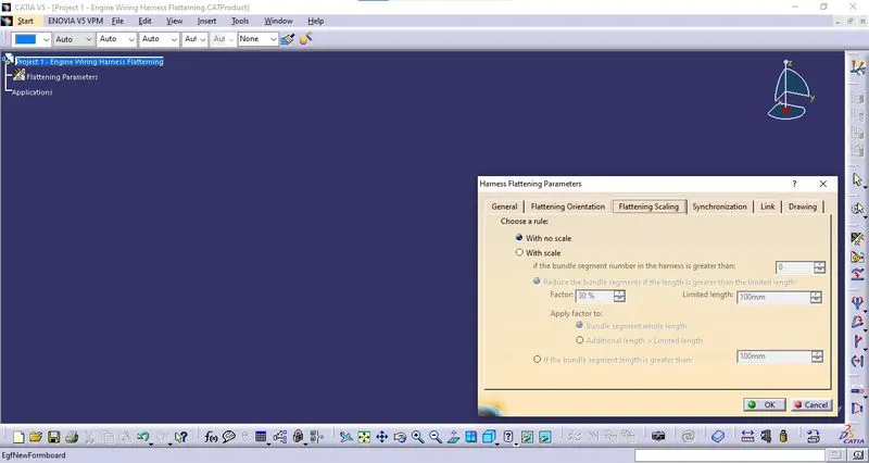
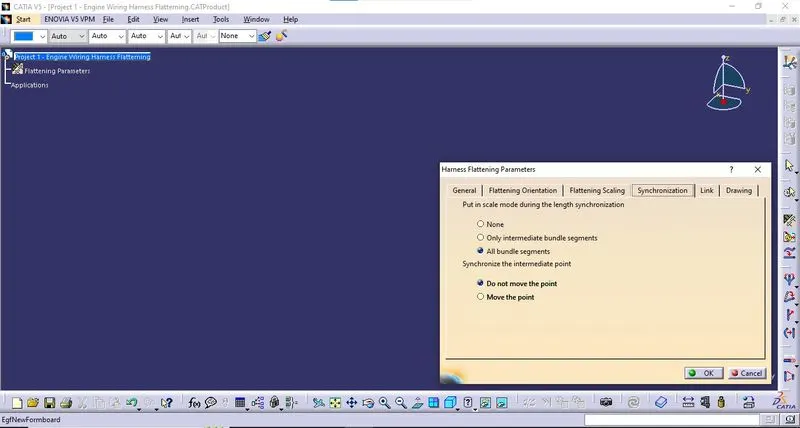
The flattening parameters were created by selecting the "Harness Flattening Parameters" tab in Electrical Harness Flatenning Workbench.
The following parameters are selected in the Harness Flattening Parameters window > General Tab
The following parameters are selected in the Harness Flattening Parameters window > Flattening Orientations Tab
The following parameters are selected in the Harness Flattening Parameters window > Flattening Scaling Tab
The following parameters are selected in the Harness Flattening Parameters window > Synchronization Tab
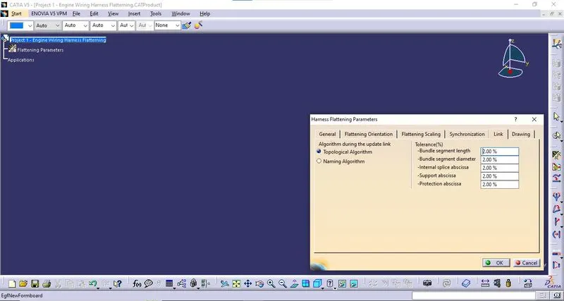
The following parameters are selected in the Harness Flattening Parameters window > Link Tab
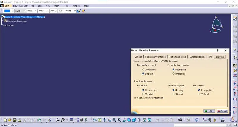
The following parameters are selected in the Harness Flattening Parameters window > Drawing Tab
iii. Import the product file:
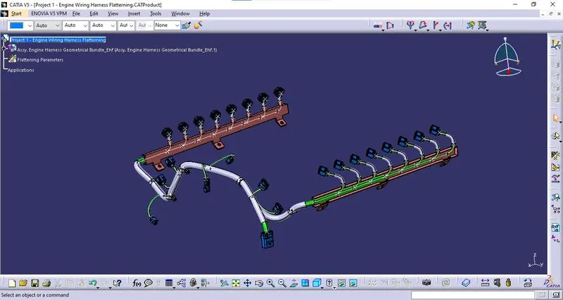
The product file to be flattened are imported by selecting the Extract command from the "Electrical Harness Flatenning" workbench.
iv. Flatten the Harness:
Flatten the imported wiring harness by selecting Flatten command. And rearrange the bundle appropriately. 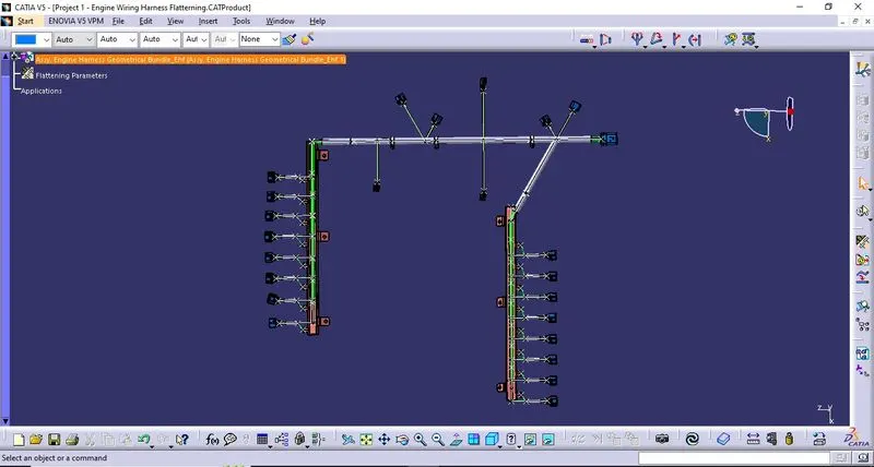
v. Save the file:
Save the product file to the desired location.
5. Creating Drawing File:
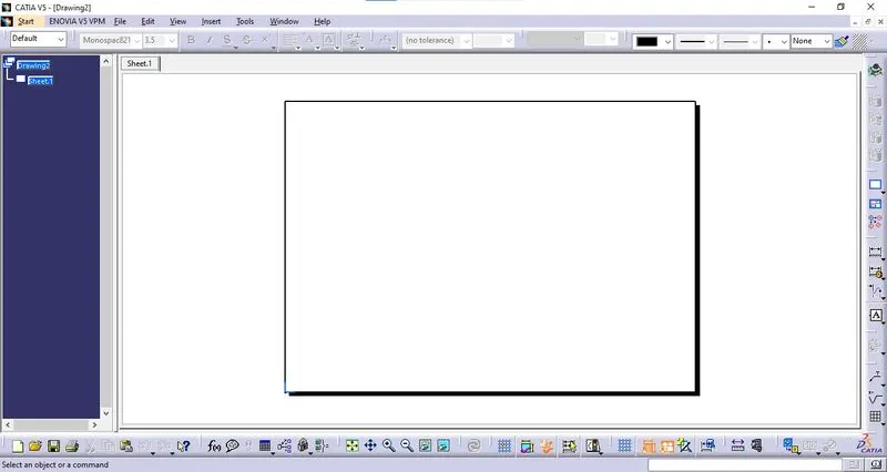
i. Create Drawing File.
Create a new drawing file by selecting New > Drawing. Choose Standard as ISO & Sheet Style as "A0 ISO".
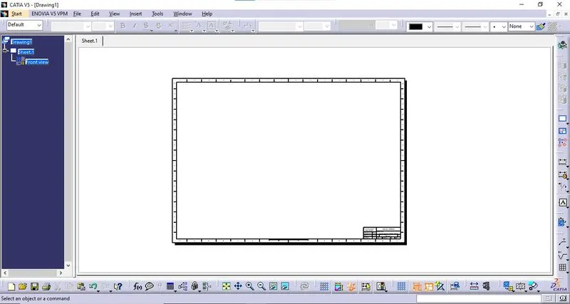
ii. Add title block:
Add title block by selecting Edit > Sheet Background. Apply a Title block by selecting the "Frame & Title Block" command. Exit the Sheet Background workspace by selecting Edit > Working Views.
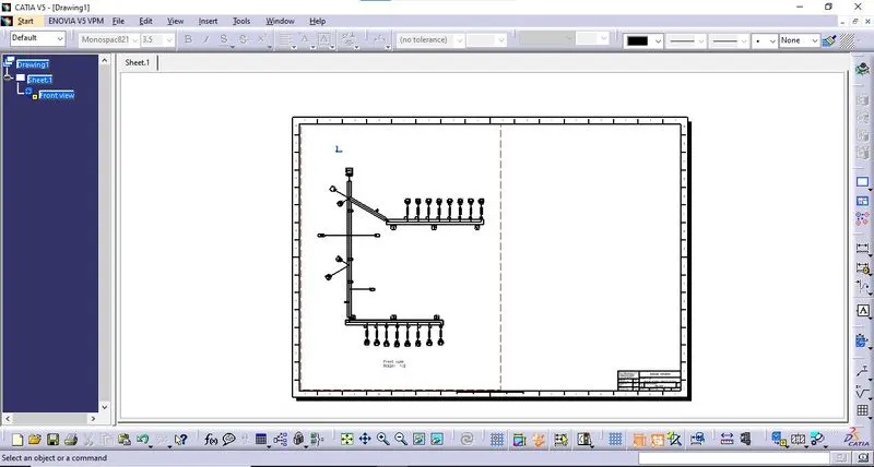
iii. Add Drawing:
Add a drawing of the product file by selecting Front View Command from Drafting Workbench. Select a surface from the product file window. Orient the harness as required using the manipulation tab.
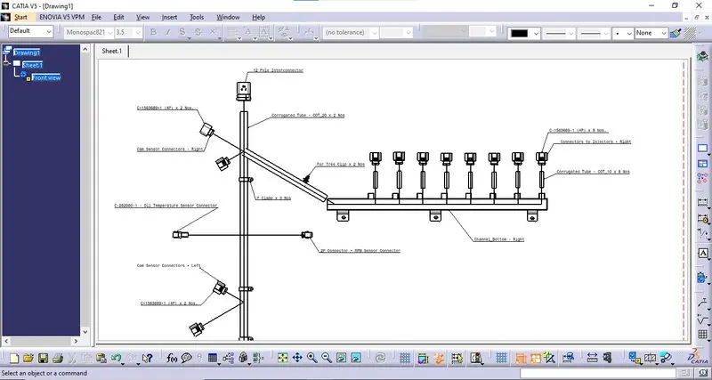
iv. Annotation:
Add annotations to the drawing as per requirement using "Text With Leader".
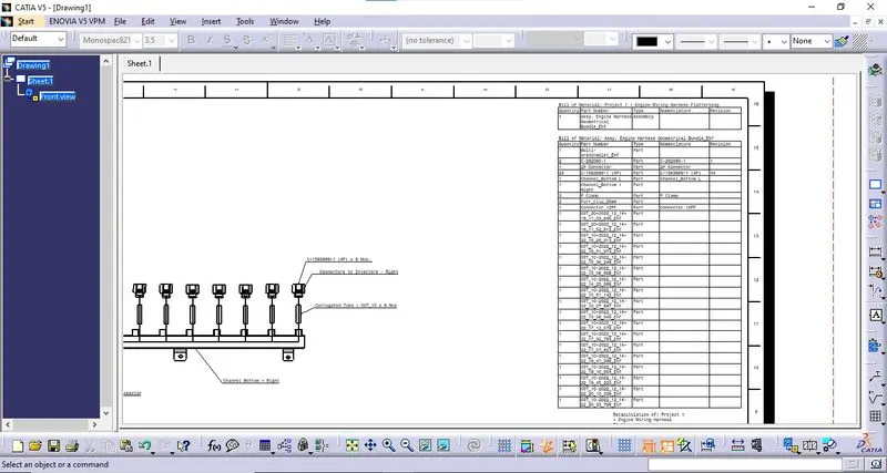
v. Bill of Material:
Create a bill of material for the drawing using the following command, Insert > Generation > Bill of Material > Bill of Material.
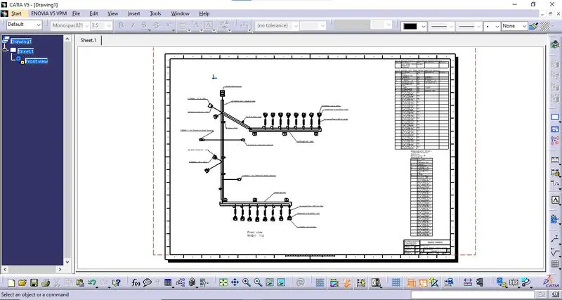
vi. Final Drawing:
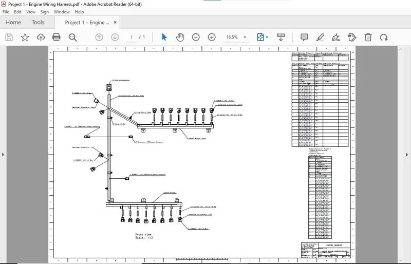
The final drawing of the flattened harness is created.
vii. Save file:
Save the file in the appropriate location.
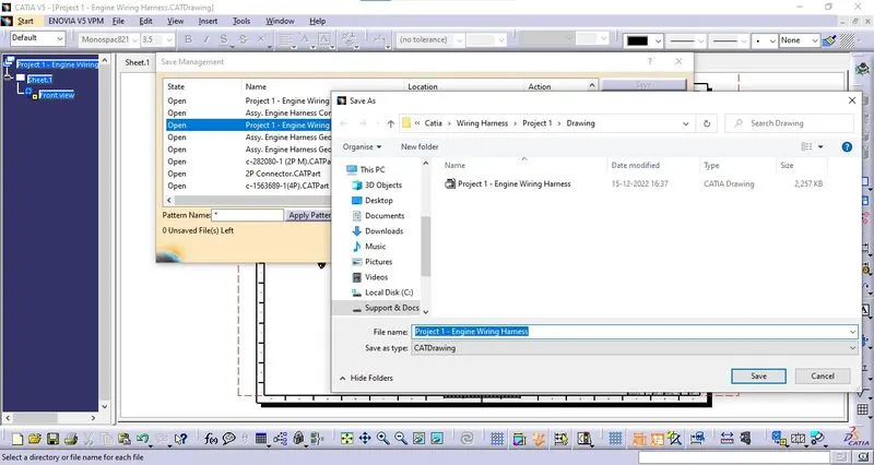
Viii. Save the file as PDF:
The wiring harness drawing is saved as a PDF by selecting File > Save As.
6. Final Report:
i. Clearance:
During the design of the Wiring Harness for the Engine, Appropriate clearance was provided in all possible situations as per industry standards.
ii. Clipping and Clamping:
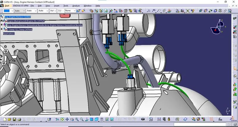
P Clamps were used to carry the main bundle since it will be easy to route the harness and also maintain proper clearance. And also because we have provision for bolts.
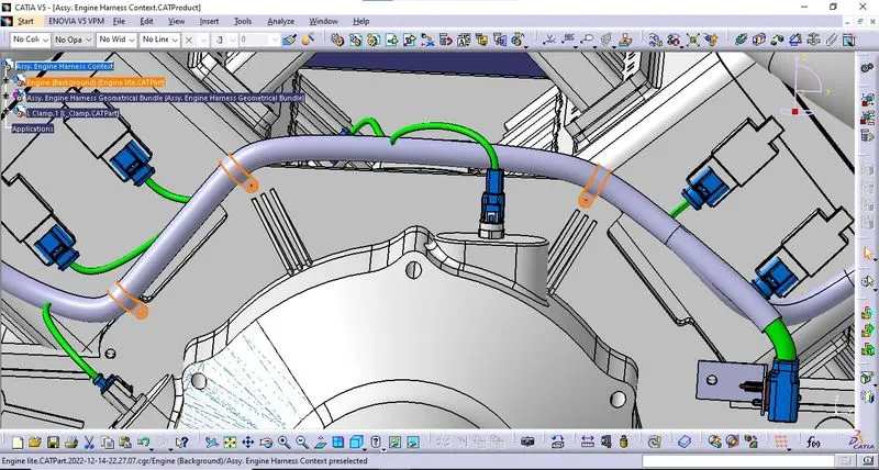
Fur Tree Clips were used in places where we cannot add a bolt or stud. This could fit in the proper hole in the mounting blocks. This ensures proper routing of the harness.
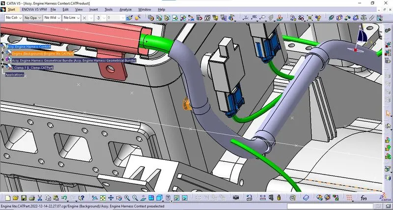
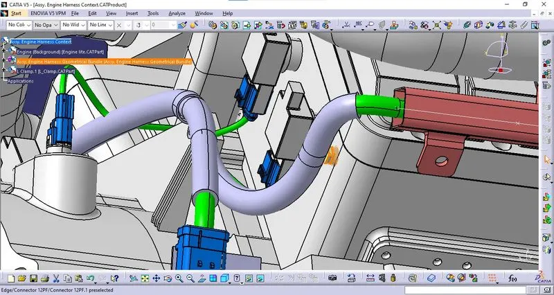
L clamp was placed along the mounting bolts of the transmission to locate the interconnector where the interconnector will be fitted firmly and make it anti-rotational. This will ensure that the harness will remain intact during the rocking of the engine.
iii. Bundle Connectivity:
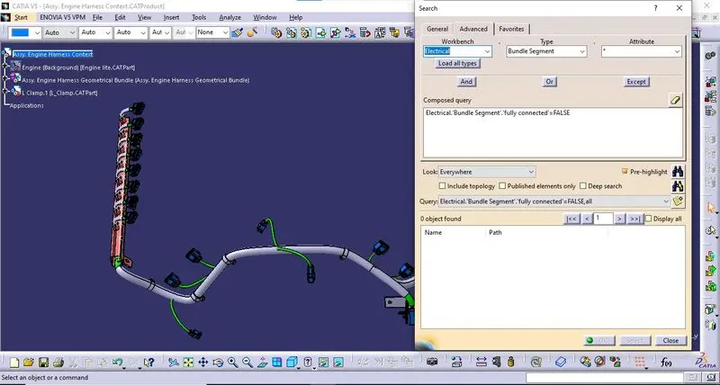
The designed harness is checked for bundle connectivity.
7. Attachments:
All the components and files used are attached as a single compressed Zip file.