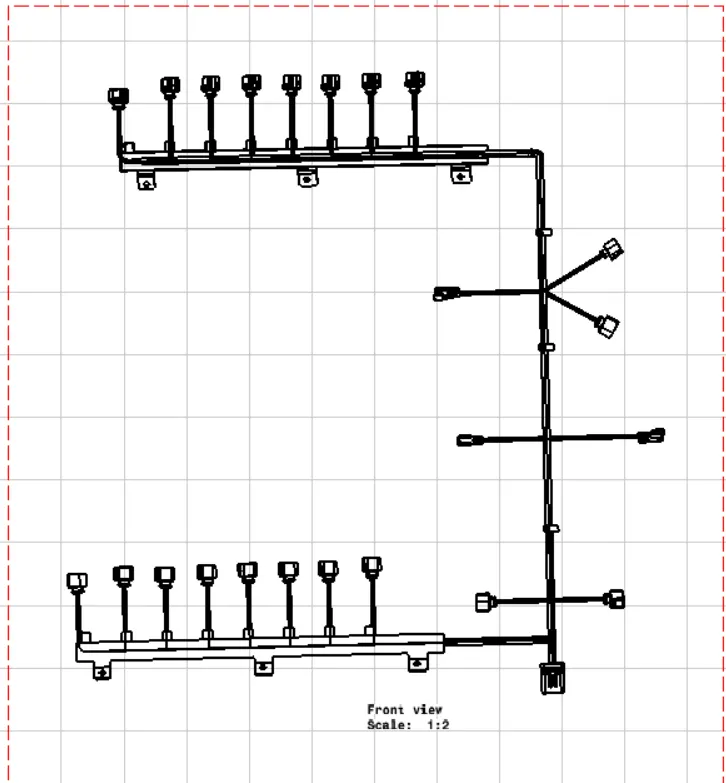
Project 1
AIM
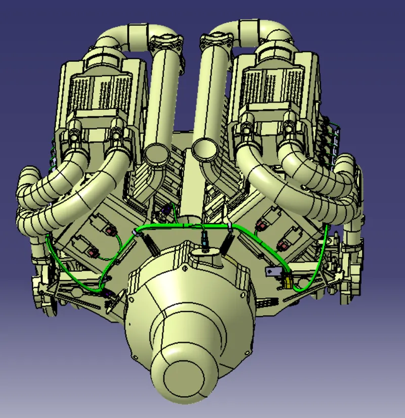
- To develop the wiring harness assembly for the Engine module through the consideration of wiring harness topology.
The following steps to route the wiring harness for Back door assembly:
- Create the Product file of Engine wiring harness context.
- Insert the Engine part to main context product.
- Insert the wiring harness assembly (Geometric bundle).
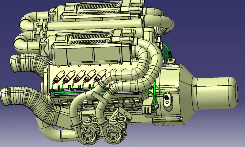
1. The Engine commodity mainly holds the Engine speed sensor, Coolant sensor, Fuel temperature, Cam shaft sensor, Position sensor & Spark Knock sensor.
2. Steps have to be followed to achieve the wiring harness routing.
- Mounting the Interconnection connector with L-Clip.
- Before Locate the conncetors for the engine It has to be defined electrically.
- Locates the appropriate connectors to the Engine according to its position.
- Placing the interconnection connector for the chassis left side.
3. Before routing the wiring harness to the Engine, consider the assumption through wiring harness topology.
WIRING HARNESS TOPOLOGY:
- It is splitting the wiring harness from main vehicle harness according to vehicles module such as(Engine, Back door, side door, roof and Instrumental panel).
- The main vehicles wiring harness connected with interconnection connector of module.
Connectors:
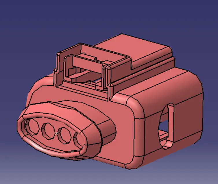
1.6 Pole connector.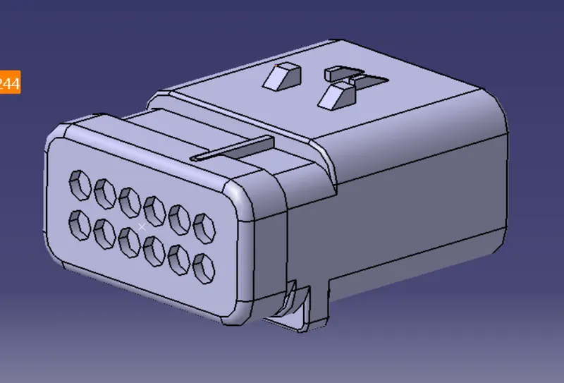 MECHANICAL PART- ELECTRICAL PART DESIGN:
- The given mechanical parts to be convert into electrical component with its properties.
- At the first, setting the certain required geometical parameters to given mechanical part such as, Connector connection point, Bundle entry point and axis system for the connectors to be inserted in the part design work bench.
- After setting these geometrical parameters navigate into the electrical part design workbench.
- Define the part as electrical connector component using the electrical device definition and define points as connector connection point and bundle entry point.
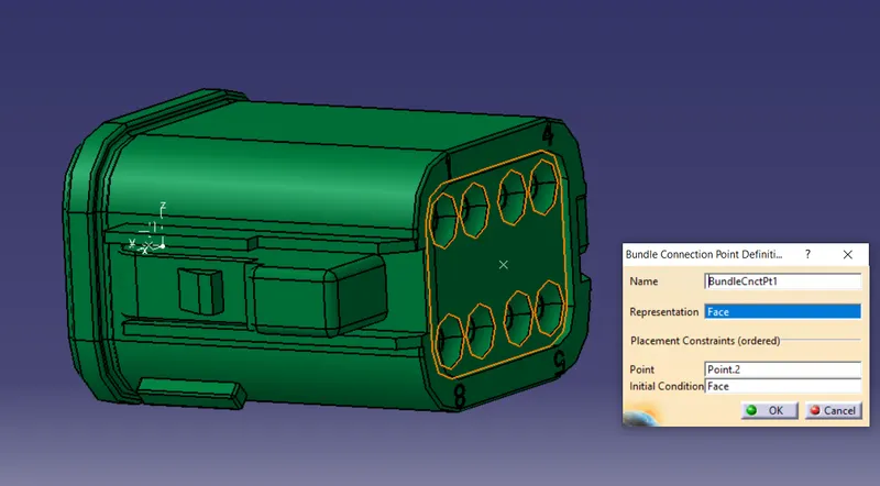
MECHANICAL PART- ELECTRICAL PART DESIGN:
- The given mechanical parts to be convert into electrical component with its properties.
- At the first, setting the certain required geometical parameters to given mechanical part such as, Connector connection point, Bundle entry point and axis system for the connectors to be inserted in the part design work bench.
- After setting these geometrical parameters navigate into the electrical part design workbench.
- Define the part as electrical connector component using the electrical device definition and define points as connector connection point and bundle entry point.
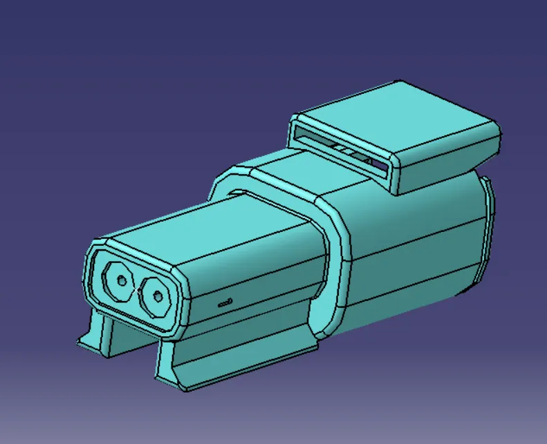
MECHANICAL PART- ELECTRICAL PART DESIGN:
- The given mechanical parts to be convert into electrical component with its properties.
- At the first, setting the certain required geometical parameters to given mechanical part such as, Connector connection point, Bundle entry point and axis system for the connectors to be inserted in the part design work bench.
- After setting these geometrical parameters navigate into the electrical part design workbench.
- Define the part as electrical connector component using the electrical device definition and define points as connector connection point and bundle entry point.
SUPPORTING ELEMENTS:
P-CLAMP:
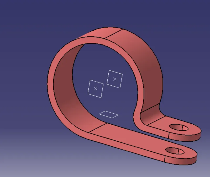
- The given mechanical parts to be convert into electrical component with its properties.
- At the first, setting the certain required geometical parameters to given mechanical part such as, bundle entry point, bundle exit point and base plane.
- After setting these geometrical parameters navigate into the electrical part design workbench.
- Define the part as electrical support component using the support definition.
FIR TREE CLIP:
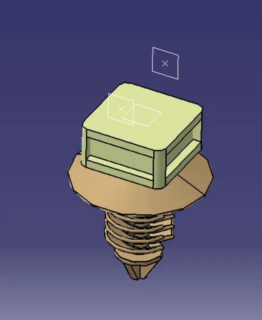
- The given mechanical parts to be convert into electrical component with its properties.
- At the first, setting the certain required geometical parameters to given mechanical part such as, bundle entry point, bundle exit point and base plane.
- After setting these geometrical parameters navigate into the electrical part design workbench.
- Define the part as electrical support component using the support definition.
PACKAGING:
- To implement the packaging of wiring harness bundle , Fix the supporting elements such as ( P-Clamp, furr tree clip, etc..).
- The supporting elements should be defined electrically.Before Routing the wiring harness bundles along with supporting elements.
- The routed wiring harness bundles along the supporting elements would be tied for maintain the bundle orientaion.
PROTECTION COVERING:
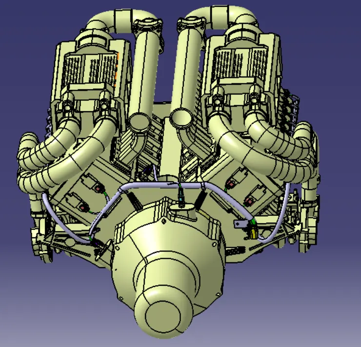
- Apply the appropriate protection covering layer (such as cot tubes, tapes, silica tubes and braided sleeves respect to its application.
- Here, The cot tubes are applied over the routed wiring harness bundles to keep protect from the sharp edges.
WIRING HARNESS FLATTENING:
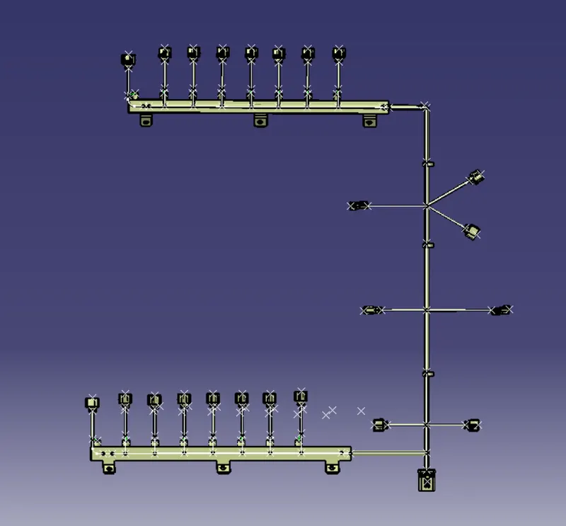
- Now by using harness flatening assembly try to flatten the geometric bundle and apply all the required operations such as bend, rotate to create the bundle in a manner .It will fit into the drawing sheet.
DRAWING