Design of battery pack
AIM:
1. To design a battery pack for a car roughly 150 Kw with 120 V. Use 3500 mAh 3.6V nominal NMC chemistry cell.
a. Design the battery pack configuration.
b. Draw the BMS topology for this battery pack.
2.To Build a 3S2P battery pack configuration with generic battery block using Matlab/Simulink.
1)
a)
Rated Voltage rating:120v
Rated power rating:150Kw
continuous current requirement: P = I * V
I = P/V
I = 150*1000/120 =1250A
Number of cells in series
Number of cells in series = Rated motor voltage / Nominal cell voltage = 120/3.6 = 33.33
Rounding off the number of cells in series
Rounding off the number of cells depends on the maximum voltage and minimum voltage
case 1
Rounding off 33.33 to 33
Nominal battery voltage = Cell nominal voltage *33 = 3.6*33=118.8 V
case 2
Rounding off 33.33 to 34
Nominal battery voltage = Cell nominal voltage *34 = 3.6*34=122.4 V
So, we can pick case 1 which is 33 cells in series
Number of cells in parallel
Cell Ah = 3.5Ah
Number of cells in parallel = continuous current/cell nominal capacity = 1250/3.5 = 357.14
Rounding of the number of cells in parallel
Number of the cells in parallel = 357.14
case 1 : Battery capacity = 357*3.5 = 1249.5Ah
case 2 : Battery capacity = 358*3.5 =1253Ah
So, we will Choose case 2
33S358P is our battery pack configuration
Now the battery pack is made of 33S358P pack so that it can meet the required output of 120v, 1250A or 120V, 150Kw
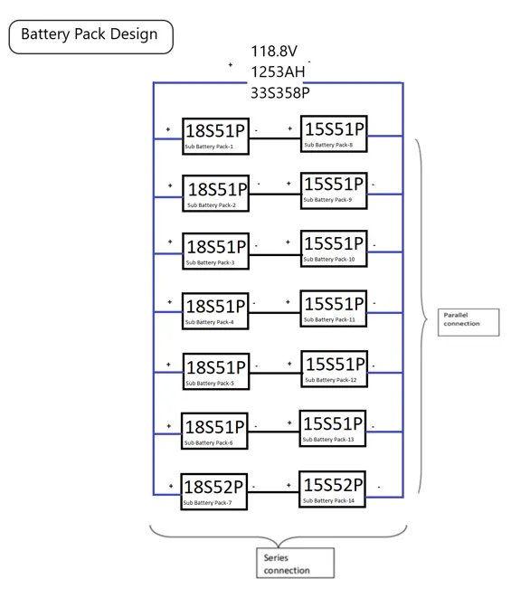
- As the BMS Supports a max of 18 cells in series so we need to divide the 33 series cells into 18 cells series sub-battery pack which leads to 2 series sub connections one with 18 and another with 15
- For each sub pack, 51 parallel cells must be created in order to create a compact parallel connection, resulting in 6 parallel connections and one 52 parallel cells connection.
- In order to achieve the requirement 33S358P, the end result is two sub-battery packs in series, one with 18 cells in series and another with 15 cells in series, as well as six sub-battery packs in parallel, one with 51 cells in parallel and one with 52 cells in parallel.
- There are two sub-battery pack configurations—18S51P and 15S51P—that together produce a 33S52P pack with seven copies. One of the packs of 33S52P is used to create 33S358P by connecting these 33S52P in parallel.
Block diagram:
- The series connection is indicated by the back line.
- The parallel connection is indicated by a blue line.
- 33S51P is created by series-connecting each 18S51P pack with each 15S51P pack.
- When all seven 33S51P (18S51+15S51) are joined in parallel, 33S358P is produced.
- In order to meet the need for 33S358P, one parallel connection is increased in the last pack's sub-pack, which contains an 18S52P series with a 15S52P pack.
b)
Battery management system:
This battery pack employs the Master and Slave BMS Topology.
It will be simple to regulate and manufacture because the whole battery pack is composed of smaller battery packs.
Two slaves can be controlled by a Master controller in a Master and Slave BMS system.
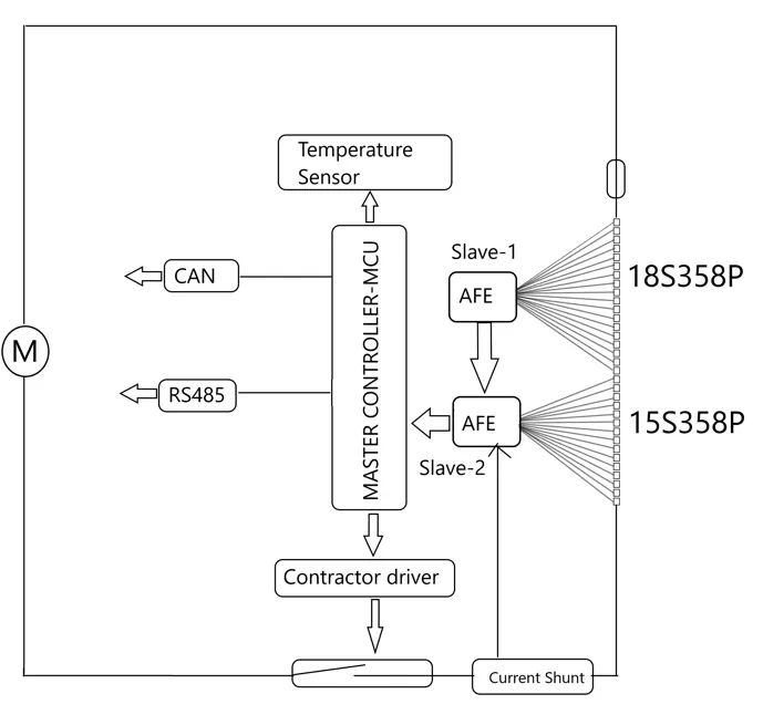
The BMS blocks are the ones inside the red line. It is built with three 18-cell slave controllers that are AFE, and they transform the analogue output from the battery's voltage sensor into a digital signal. As depicted, there are two slaves connected in series. Slave-1 will collect data from module-1 and pass it to slave-2, who will then collect data from module-2. Slave-2 then combines the data from slaves-1 and 2 and sends it all to the master controller, which is an MCU. It manages the battery pack in accordance with the protocols that the MCU is provided.
We can also use the combination of 7 Master and slave BMS i.e., 2 slaves 18S356P and 15S356P and a master controller of 7 numbers. All master control will have one single controller or all 7 master controllers can be directly connected to the MCU. But it's a costly and complicated process.
2)
A 3s2p battery pack consists of 3 cells in series and 2 cells in parallel each. It is implemented in Simulink environment as shown below.
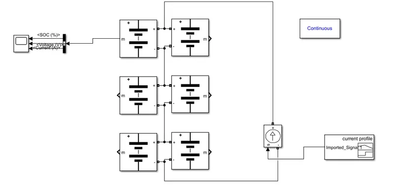
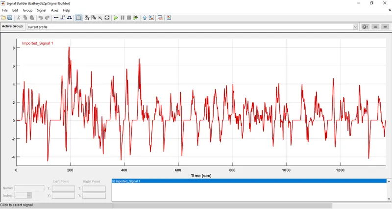
A current source has been introduced to simulate dischage effect. A UDDS drive cycle has been given as input which looks as shown below
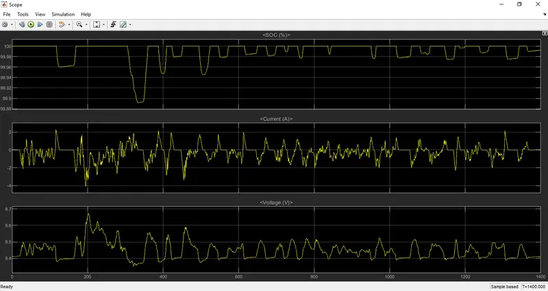
The output voltage, current and SOC are