Power Converter
AIM: To study the power converter devices and methods of digital and analog devices.
OBJECTIVES:
1. a.) Why does the MATLAB PID autotuner doesn’t work for a power converter? Show step-wise process for a buck-boost converter circuit.
b.) Explain the importance of ADC and DAC blocks in closed-loop control of power converters.
2. a.) What are the three basic boolean operators for the logic gates in digital electronics?
b.) Form the truth table for all the above boolean operations. Realize the operations in Simulink using suitable logic gates from the library browser.
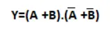
c.) Draw the circuit and truth table to implement the following logic in Simulink.
(Hint- Complement of 1 is 0 and complement of 0 is 1.)
3. Carry out the following binary operations. Verify the results in MATLAB.
a.) 11111 and 10101(AND operation)
b.) 111 and 000(OR operation)
c.) 1010111 and 0101100 (AND operation)
d.) 101110(NOT operation)
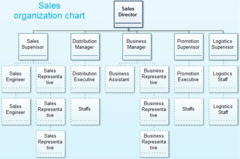
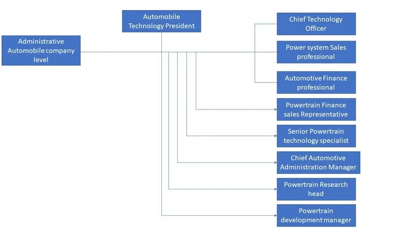
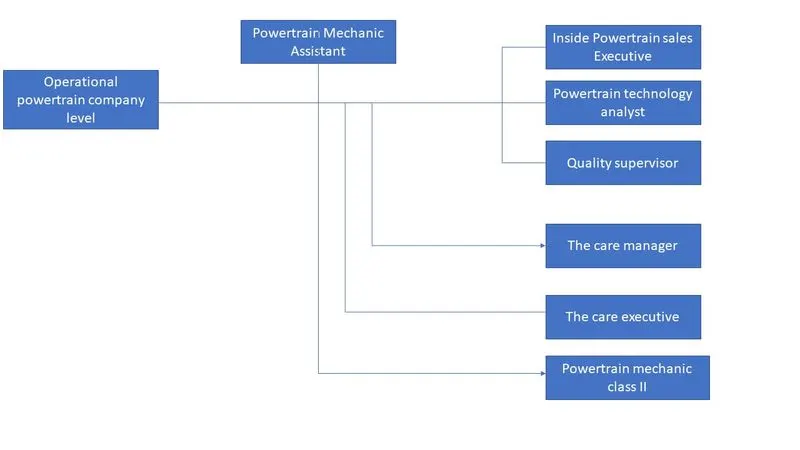
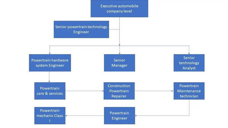
4. Prepare an organizational chart of people working at electric powertrain manufacturing companies.
(Hint: Refer to the organizational chart for a sales team attached below).
OBJECTIVE 1 -
1. a.) Why does the MATLAB PID autotuner doesn’t work for a power converter? Show step-wise process for a buck-boost converter circuit.
b.) Explain the importance of ADC and DAC blocks in closed-loop control of power converters.
1. a.) Why does the MATLAB PID autotuner doesn’t work for a power converter? Show step-wise process for a buck-boost converter circuit.
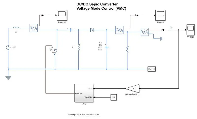
Step I Attempt to autotune using the tune button
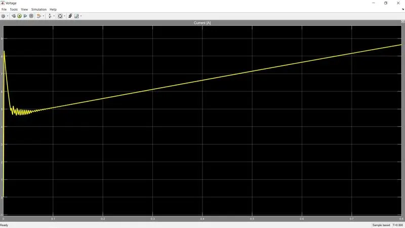
The auto-tune won't work as the system is nonlinear.
Step II Plant cannot be linearized; alternate method needed. Using input and output data, a transfer function is estimated.
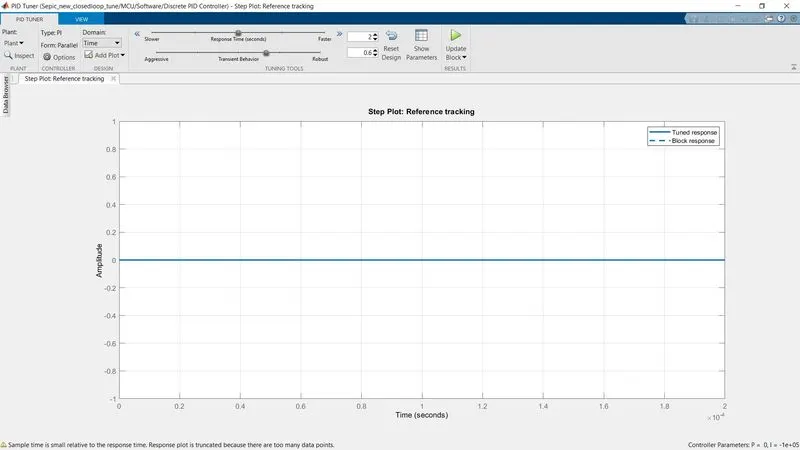
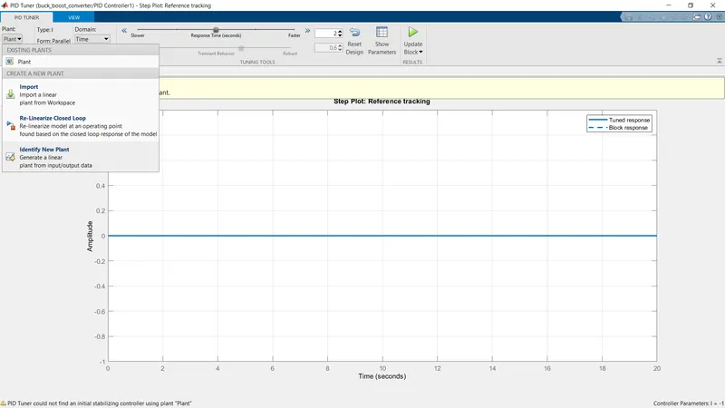
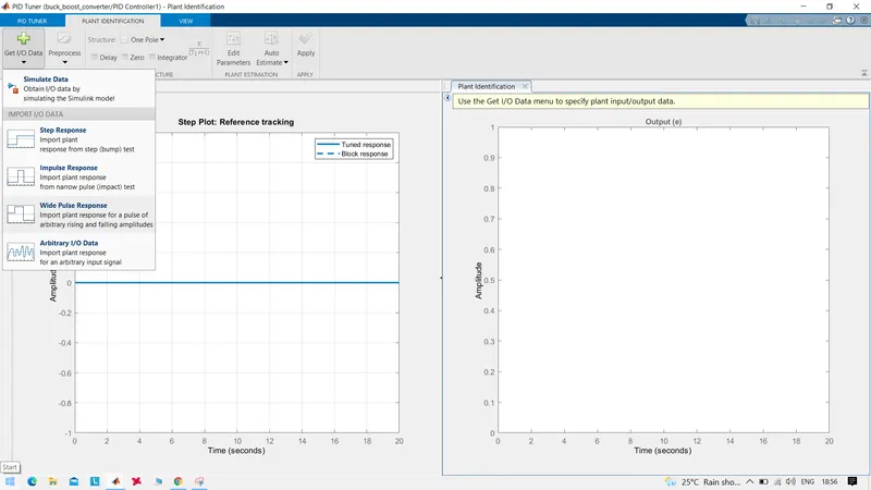
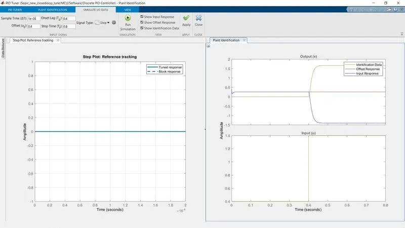
Enter the accurate offset value and the step value to the simulation data
Step 3: Apply simulation results and test structure of TF for accuracy and verification.
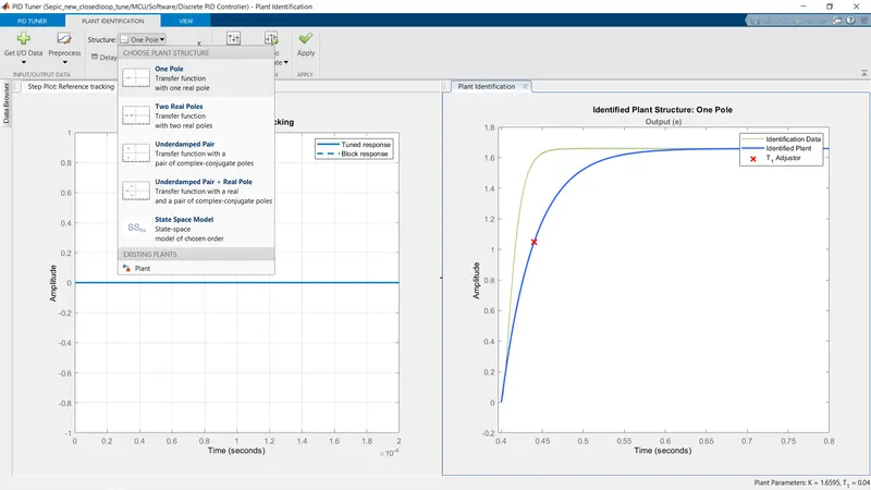
For our simulation, we will be selecting the Underdamped pair of the poles and zeros.
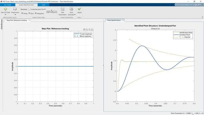
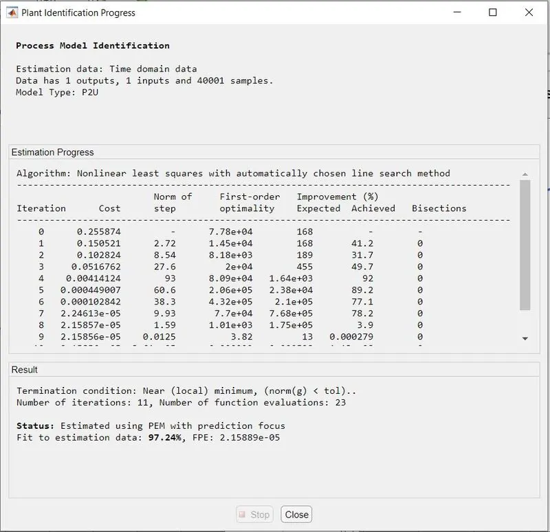
- A fit estimation of 97.24% is excellent, so these results can be applied.
Step 4: Apply results and adjust response time and transient behavior (not available in this case) according to performance requirements. Click "Update Block" to tune the PID/Integral controller
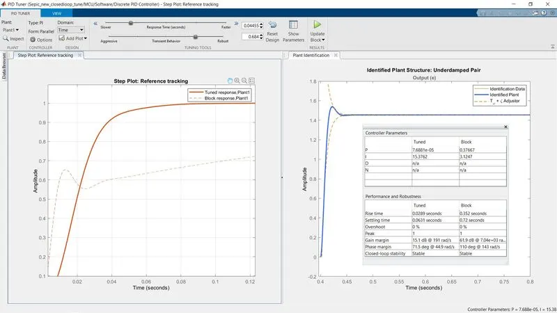
- Now we can tune the response of the output as per our requirement using the tunning bars.
OUTPUT RESULT
The input voltage is at 5V and the reference voltage is 20V
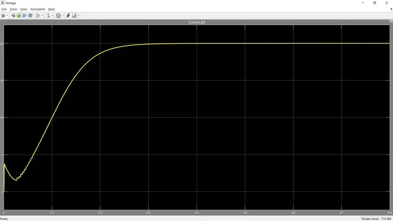
Change the reference voltage to 25V
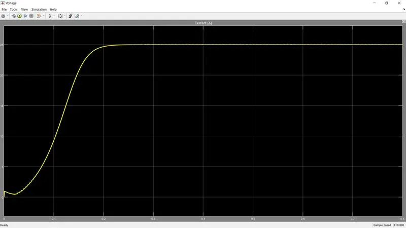
- As we can see, despite the low input voltage, we can boot out voltage to the required output voltage using these circuits.
b.) Explain the importance of ADC and DAC blocks in closed-loop control of power converters.
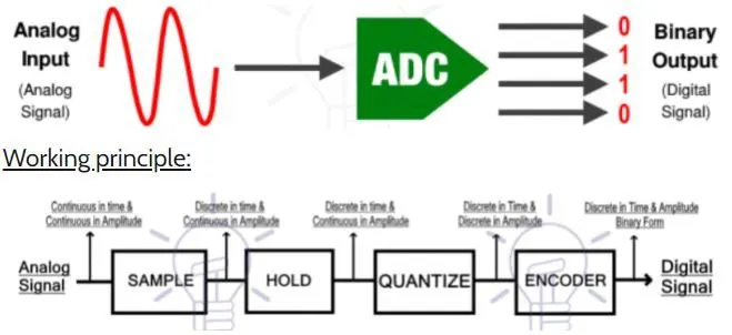
Why Analog to Digital Converter (ADC)?
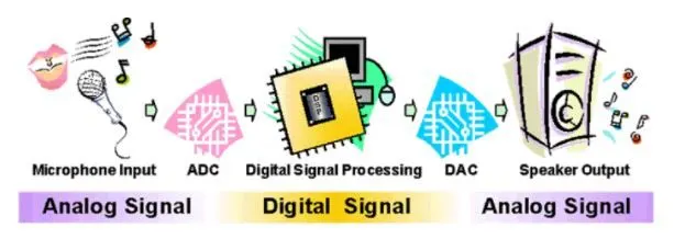
In the real world, every real quantity such as voice, temperature, weight, etc exists in the analog state and it cannot be processed by any digital device such as a computer or a cell phone.
Sample and hold:
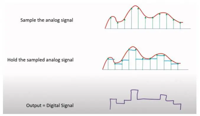
- The sample block function is to sample the input analog signal at a specific time interval. The samples are taken in continuous amplitude & possess real value but they are discrete with respect to time.
- The second block used in ADC is the ‘Hold’ block. It has no function. It only holds the sample amplitude until the next sample is taken. The holding value remains unchanged till the next sample
- The on-hold continuous amplitude value in the holding block goes through the ‘quantize’ block & becomes discrete in amplitude
- The encoder block converts the digital signal into binary form i.e. into bits. Digital devices operate on binary signals so it is necessary to convert the digital signal into the binary form using the Encoder
Why Digital to Analog Converter (DAC)?
Computers can only understand a data signal in the digital domain in order to process and/or finetune it. DAC converts these bits into an analog voltage or current. The processing speed of a digital computer is very fast & can compute or process any data in a matter of microseconds. It conserves time & helps in processing complex data according to our needs.

Working principle:
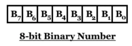
Bit weight = `2^n`
Bit weight of 4th bit from left = `2^n = 2^3 = 8`
Example: 10011
10011 = `1 .2^4+0.2^3+0.2^2+1.2^1+1.2^0 =19`
This is how the DAC works by adding the weights of all corresponding bits with its value to generate the analog value at its output.
Applications of ADC and DAC:
- ADC converts the analog signal collected by audio input equipment, such as a microphone, into a digital signal that can be processed by computer. The computer may add sound effects such as echo and adjust the tempo and pitch of the music. DAC converts the processed digital signal back into the analog signal that is used by audio output equipment such as a speaker.
- Motor control: motor is embedded with a microcontroller. The microcontroller generates a digital signal to vary the speed of the motor which is converted into an analog signal using a DAC
- Cell phones operate on the digital voice signal. Originally the voice is in analog form, which is converted through ADC before feeding to the cell phone transmitter
- Medical Imaging like x-ray & MRI also uses ADC to convert images into Digital form before modification. They are then modified for better understanding
- Music from the cassette is also converted into the digital form such as CDs and thumb drives using ADC converters
- Air conditioner contains temperature sensors for maintaining the room temperature. This temperature is converted into digital form using ADC so that onboard controller can read & adjust the cooling effect.
Objective 2
a.) What are the three basic boolean operators for the logic gates in digital electronics?
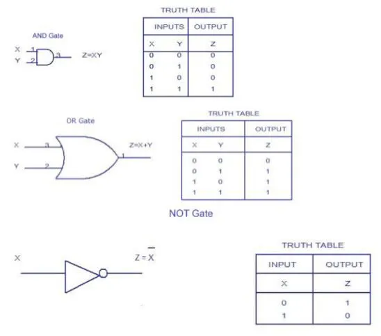
b.) Form the truth table for all the above boolean operations. Realize the operations in Simulink using suitable logic gates from the library browser.
c.) Draw the circuit and truth table to implement the following logic in Simulink.
(Hint- Complement of 1 is 0 and complement of 0 is 1.)
a.) What are the three basic boolean operators for the logic gates in digital electronics?
AND, OR, NOT
b.) Form the truth table for all the above boolean operations. Realize the operations in Simulink using suitable logic gates from the library browser.
c.) Draw the circuit and truth table to implement the following logic in Simulink.
(Hint- Complement of 1 is 0 and complement of 0 is 1.)
Y = AA' + AB' + BA' + BB'
Y = AA' + AB' + BA' + BB'
Y = AB' +BA'
Truth table
| A | B | AB' | BA' | Output |
| 0 | 0 | 0 | 0 | 0 |
| 0 | 1 | 0 | 1 | 1 |
| 1 | 0 | 1 | 0 | 1 |
| 1 | 1 | 0 | 0 | 0 |
A = 0, B = 0: A = 0, B = 1:
AB' + BA'
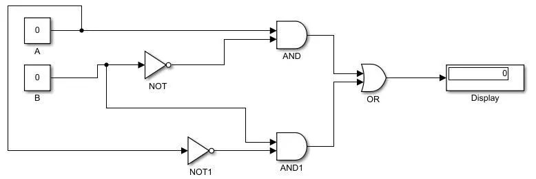
AB' + BA'
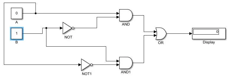
A = 1, B = 0: A =1, B=1:
AB' + BA'
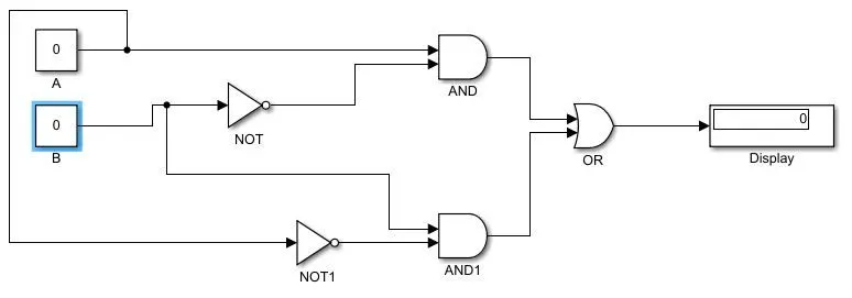
AB' + BA'
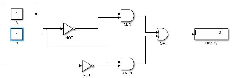
OBJECTIVE 3 -
Carry out the following binary operations. Verify the results in MATLAB.
a.) 11111 and 10101(AND operation)
b.) 111 and 000(OR operation)
c.) 1010111 and 0101100 (AND operation)
d.) 101110(NOT operation)
clear all
close all
clc

a=[1 1 1 1 1];
b=[1 0 1 0 1];
ansa = bitand(a,b)

c = [1 1 1];
d = [0 0 0];
ansb = bitor(c,d)

e=[1 0 1 0 1 1 1];
f=[0 1 0 1 1 0 0];
ansc = bitand (e,f)

g = [1 0 1 1 1 0];
ansd = not(g)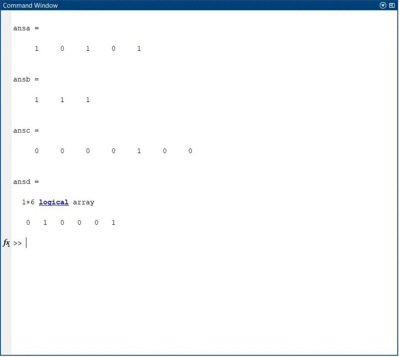
OBJECTIVE 4 - Prepare an organizational chart of people working at electric powertrain manufacturing companies.
CONCLUSION
Here we have successfully studied tuning the nonlinear system, learn about the digital and analog systems. Studied the important gated and their effect using Matlab and Simulink. Handled the digital data using the operations of the gate with the help of a code. Lastly studied the organizational chart of electrical powertrain companies.