Planetary Gear
AIM -
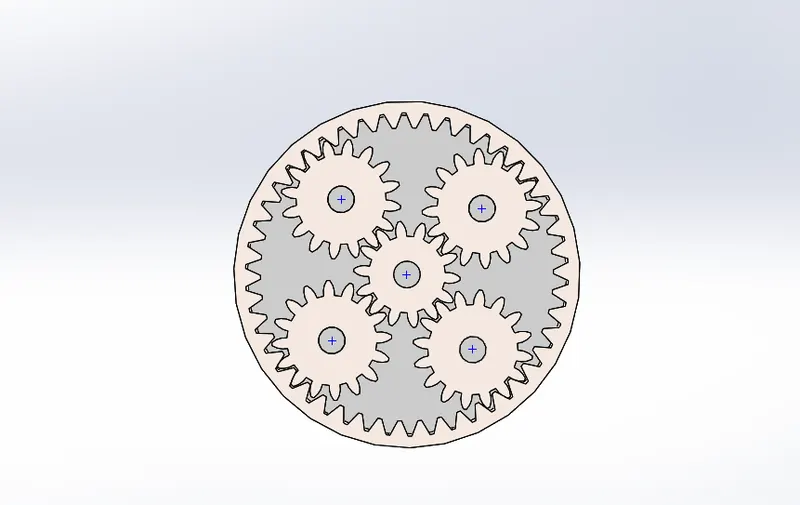
To run the motion analysis on the planetary gear with a sun gear a carrier and four planet gears.
- To access the gears from the toolbox in solidworks present in the ANSI metric system.
- Provide the required parameters for defining each and every gear.
- Designing the carrier depending upon the shaft diameter of the planet gears.
- Assembling them in solidworks and giving correct constraints to all the parts so that the assembly is perfect for running the motion analysis study.
THEORY -
Planetary gears are the heart of modern engineering and are used in gearboxes that power everythingfrom basic plant machinery to cutting edge elecric vehicles. The simple configration of a central drive and orbiting gears was developed thousands of years ago model the movements of planets.
A simple planetary gear set is made up of three main components:
- The sun gear that sits in the centre(central gear).
- Multiple planet gears.
- The ring gear(outer gear)
The load from the sun gear is distributed to several planeteary gears which can either be used to drive an outer ring or a shaft or spindle. The central sun gear takes a high speed, low torqueinput. it drives several rotating external gears which increases the torque.
CALCULATIONS:
GIVEN
Ring gear
- Module = 2.5(You must use metric system in design modeler)
- Number of teeth = 46
Sun gear
- Number of teeth = 14
- Input speed of the gear = 200 rpm
- Number of planet gears = 4
for calculating diameter of pitch diameter of sun gear and ring gear
D= m*T
d - pitch diameter
m - module
T - no. of teeth
for Ring gear -
d = (2.5)*(46)
d = 115
for sun gear - (module is same for all gears)
d = (2.5)*(14)
d = 35
for planet gears -
To fing pitch diameter
radius of ring gear = Radius of sun gear + diameter of planet gear
(115/2) = (35/2) + diameter of planet gear
d = 40
from above pitch diameter
d = m * t
no.of teeth(t) = 16
| Gear | module(m) | No.of teeth (t) | Pitch diameter(d) |
| Ring gear | 2.5 | 46 | 115 |
| Sun gear | 2.5 | 14 | 35 |
| Planet gear | 2.5 | 16 | 40 |
3D models -
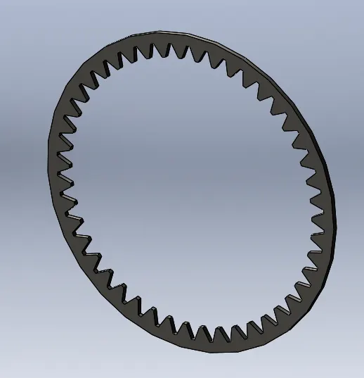
Ring gear
module = 2.5, no.of teeth =46, Pitch diameter = 115.
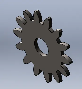
Sun gear -
module = 2.5, no.of teeth =14, Pitch diameter = 35,Nominal shaft diameter = 10
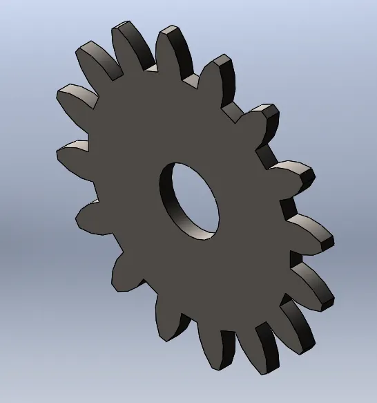
Planet gear
module = 2.5, no.of teeth =16, Pitch diameter = 40,Nominal shaft diameter = 10
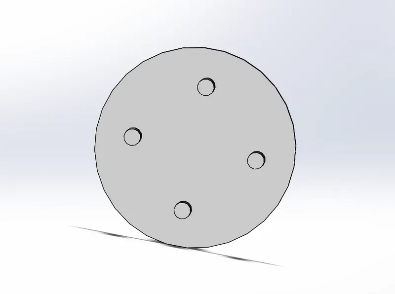
Carrier -
Final assembly -
MOTION STUDY SETUP -
- The carrier is designed as part file by using the obtained dimensions
- In solidworks assembly from design library the required number and types of gears like internal spur gear and spur gear are choosen from the ANSI metric system.
- The gears are constrained according to the requirment.
- The motion study is conducted by following steps
- Solidworks motion is enabled from the solidworks add ins.
- In each of the 3 cases the input element is provided a rotary motor with a constant speed 200RPM.
- Then the element to be fixed using the fix option.
- Then solid contact should be provided using contact option and material should be selected as steel(Dry).
- Then calculate option is used and simulation was done
- The required plots were obtained.
Results -
Conditions to carry out simulation , Input - 200 RPM
| Sl.No | Input | Output | Fixed |
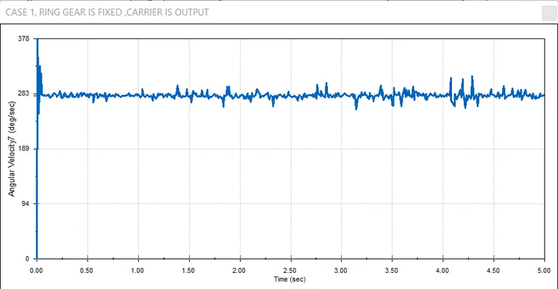
| 1 | Sun Gear | Carrier | Ring Gear |
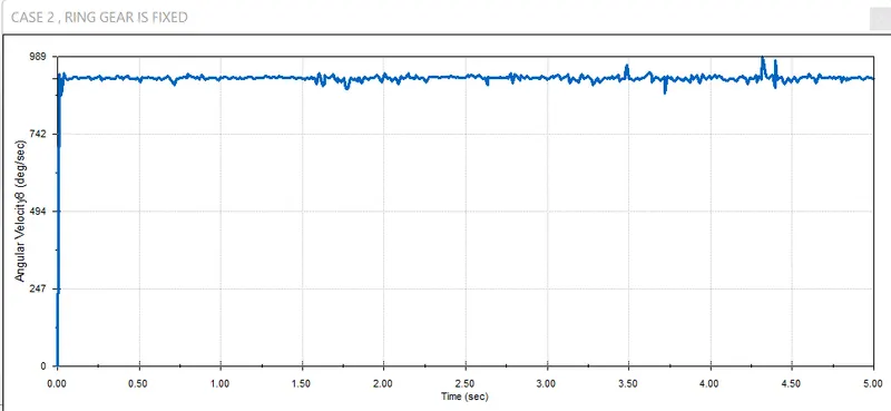
| 2 | Ring Gear | Carrier | Sun Gear |
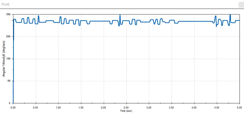
| 3 | Sun Gear | Ring Gear | Carrier |
CASE -1
CASE -2
CASE -3
Animation links -
case 1 - https://drive.google.com/file/d/1Ca31CoI4Ykd9ET9odZ0m327akGWQGaUd/view?usp=sharing
case 2 - https://drive.google.com/file/d/17eK1cYtk2LGcQx4l8TJGarvx-77VW0N5/view?usp=sharing
case 3 - https://drive.google.com/file/d/1chcRwHAPjdEOEVbs5jVQD0qQkwiY3bZb/view?usp=sharing
CONCLUSION -
So, the motion analysis was sucessfully and working of planetary gear system was studied.