Planetary Gear
AIM:
Plot the angular velocity at the output in the following cases of the planetary gear train and compare.
|
S.No |
Input |
Output |
Fixed |
|
1 |
Sun Gear |
Carrier |
Ring Gear |
|
2 |
Ring Gear |
Carrier |
Sun Gear |
|
3 |
Sun Gear |
Ring Gear |
Carrier |
INTRODUCTION AND THEORY FOR THE TOPICS OF CHALLENGES:
There are mainly four important parts in a planetary gear train
- RING GEAR
- SUN GEAR
- PLANET GEAR
- CARRIER/ ARM/ SPIDER.
As we all know gears are an important type of power transmission system.
Generally, in planetary gear train number of planet gears are more than one because of two reasons
- For the balancing of the gear train.
- For load distribution among the planate gears in power transmission.
In a planetary gear train, one gear is fixed either sun gear or ring gear. So it becomes an “kinematic chain”.
SHOW AND EXPLAIN THE ENTIRE STUDY SETUP:
CALCULATION:
We have to design our gear train with the help of this given data and calculate the remaining.
- Ring Gear
- Module = 2.5 (You must use the metric system in the design modeler)
- Number of teeth = 46
- Sun Gear
- Number of teeth = 14
- Planet Gear
- Number of planet gears = 4
- Input Speed of the Gear = 200 rpm.
We need to calculate the pitch circle diameter of all gears and the number of teeth for the planet gear. Since the module of all the gears is the same.
|
Module = Pitch Circle Diameter (PCD) No.of Teeth (T) |
ring gear:
PCD = 2.5* 46 = 115 mm
PCD of the ring gear is 115 mm.
sun gear:
PCD = 2.5* 14 = 35 mm
PCD of the sun gear is 35 mm.
planet gear:
(PCD/2)RING = (PCD)PLANET + (PCD/2)SUN
(115/2) = (PCD)PLANET + (35/2)
(PCD)PLANET = 40 mm
PCD of the planet gear is 40 mm
No. of Teeth = PCD /MODULE = 40/ 2.5 = 16
No. of Teeth in planet gear is 16.
DESIGN:
We can design a gear in an inch and metric system. So here we are choosing the metric system since all the dimensions are in mm.
First, open a new assembly file and go to the design library and click on toolbox now select the type of system as ANSI-METRIC and clock on power transmission systems and click on gears and select as per your requirement.
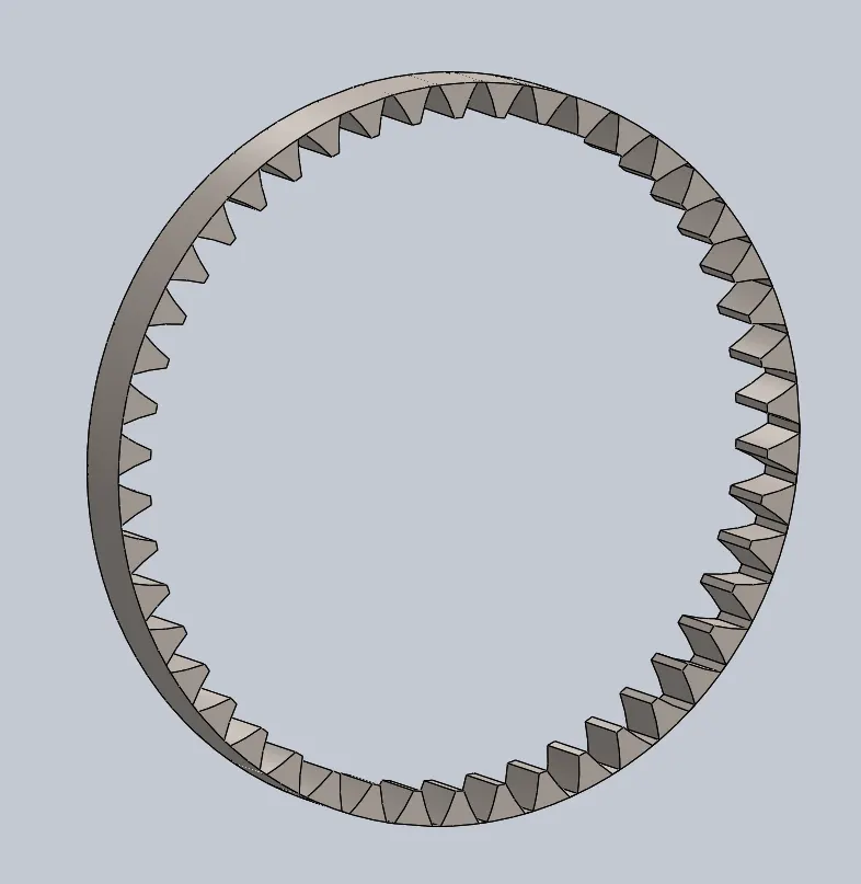
- INTERNAL SPUR GEAR. (RING GEAR)
Giving requires shape and size of the gear like module 2.5, teeth 46, pressure angle 20, face width 12, outer diameter 25. Click ok and press esc.
Now the required gear is generated and saved as a part file.
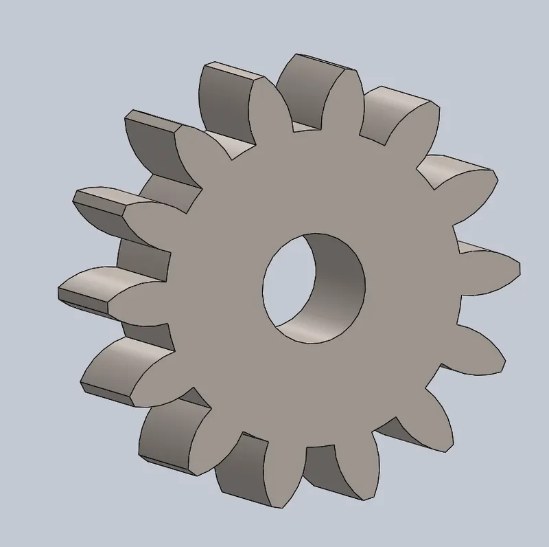
- SPUR GEAR. (SUN GEAR)
Giving requires shape and size of the gear like module 2.5, teeth 14, pressure angle 20, face width 12, shaft diameter 10. Click ok and press esc.
Now the required gear is generated and saved as a part file.
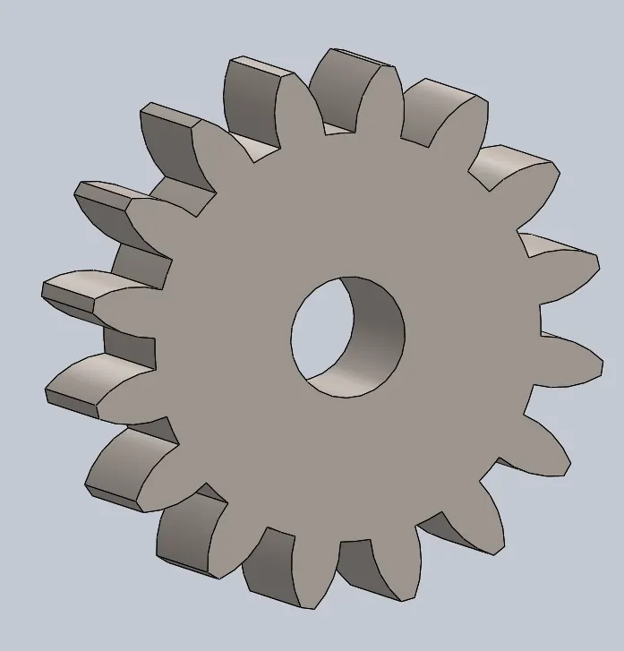
- SPUR GEAR. (PLANET GEAR)
Giving requires shape and size of the gear like module 2.5, teeth 16, pressure angle 20, face width 12, shaft diameter 10. Click ok and press esc.
Now the required gear is generated and saved as a part file.
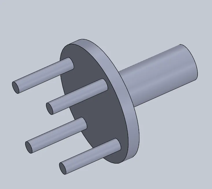
Now we have to design coupling/carriage:
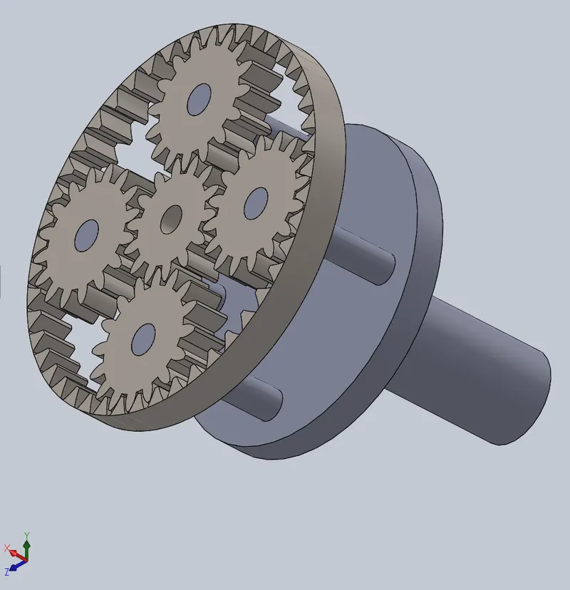
Open a new part file and select the front plane and click on sketch draw a circle of diameter 115 mm and extrude it for a thickness of mm. and select the surface and draw a circle of 10 mm at a horizontal distance of 37.5 mm and use circular pattern and give number od circles to be 4 and exit sketch and extrude the circles to the length of 50 mm. now click on the opposite face and draw a circle of diameter 30 mm and extrude it to the length of 75 mm. therefore now this coupling can hold 4 planetary gears and an output shaft.
ASSEMBLY:
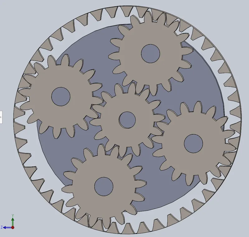
With the help of browse get all the four parts for our assembly and now start to constrain the motion of all the gears first we mate the surface of the ring gear and sun gear to coincident mate and concentric mate. Now we mate all the planet gear and ring gear for a coincident mate. Now we use concentric mate for all four planet gears and shafts of the coupling. And now at last we use coincident mate for planet gear surface and shaft end face.
Gear allayment:
Here we not using the mechanical gear mate option otherwise the gears will automatically alliin with each other.
First fix the sun gear and alliin all the planet gears and now by moving ring gear to alliin with planet gears.
Right side view: Isometric view:
MOTION ANALYSIS:
Case 1: fix the ring gear and give input to the sun gear and get the output on the carrier
Click on show hidden axis and go to solidworks add-in and select solidworks motion now click on motion study and select motion study option and click on the motor to give input to the sun gear as 200 rpm and click ok. And then click on solid contact and select all the gears and coupling and give the material as steel (dry) and click ok. Now click on calculate to RUN the analysis.
Case 2: fix the sun gear and give input to the ring gear and get the output on the carrier
First, create a new motion study and then delete the previous motion study and click on the model and change the compounds to be fixed and others to float. Click on show hidden axis and go to solidworks add-in and select solidworks motion now click on motion study and select motion study option and click on the motor to give input to the ring gear as 200 rpm and click ok. And then click on solid contact and select all the gears and coupling and give the material as steel (dry) and click ok. Now click on calculate to RUN the analysis.
Case 3: fix the carrier and give input to the sun gear and get the output on the ring gear
First, create a new motion study and then delete the previous motion study and click on the model and change the compounds to be fixed and others to float. Click on show hidden axis and go to solidworks add-in and select solidworks motion now click on motion study and select motion study option and click on the motor to give input to the sun gear as 200 rpm and click ok. And then click on solid contact and select all the gears and coupling and give the material as steel (dry) and click ok. Now click on calculate to RUN the analysis.
RESULTS AND EXPLANATION:
Statement 1: As we know efficiency is directly proportional to power.
Statement 2: And the power is directly proportional to torque and angular velocity.
From Statement 1 and 2 we can say that the efficiency of the gear is proportional to the angular velocity. Therefore, by a change in angular velocity, we can change the power delivery of the system and change the efficiency of the gear train.
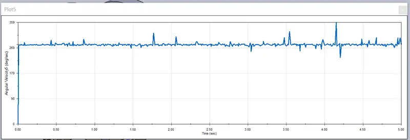
Case 1: fix the ring gear and give input to the sun gear and get the output on the carrier
After calculation click on the plot and select velocity and then angular velocity and select magnitude and then select the output surface carrier click ok. The plot will automatically generate angular velocity vs time.
Case 2: fix the sun gear and give input to the ring gear and get the output on the carrier
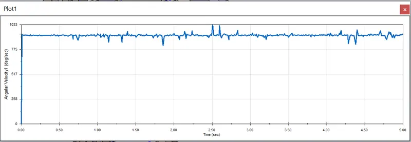
After calculation click on the plot and select velocity and then angular velocity and select magnitude and then select the output surface carrier click ok. The plot will automatically generate angular velocity vs time.
Case 3: fix the carrier and give input to the sun gear and get the output on ring gear
After calculation click on the plot and select velocity and then angular velocity and select magnitude and then select the output surface ring gear click ok. The plot will automatically generate angular velocity vs time.
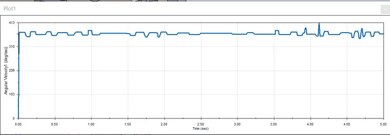
ANGULAR VELOCITY(w):
(w)case2 > (w)case 3 > (w)case1
Case 1 can use for high torque application, case 2 can be used for high-speed application
ANIMATION:
CASE 1: https://drive.google.com/file/d/13CmxMX4flFJh6gGVvI0PIavBpk32buGa/view?usp=sharing
CASE 2: https://drive.google.com/file/d/1A_2xd3S-kzsvVSVZ-8mqwD8db1tK1dNF/view?usp=sharing
CASE 3: https://drive.google.com/file/d/1UW2kEbHnKsqgYCEaLgsoCrGxbv4aKtk4/view?usp=sharing