Planetary Gear
Aim: To model and run a motion analysis on Planetary Gear System.
Introduction:
An epicyclic gear train or planetary gear consists of 2-4 gears mounted so that the center of one gear revolves around the center of the other. The planet and sun gears mesh so that their pitch circles roll without slip.
The sun gear is located at the center, and transmits torque to the planet gears which are typically mounted on a moveable carrier . The planet gears orbit around the sun gear and mesh with an outer ring gear . Planetary gear systems can vary in complexity from very simple to intricate compound systems, depending on the application.
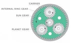
Components used for this challenge:
a. Sun Gear-1
b. Ring Gear-1
c. Planetary Gear-4
d. Carrier-1
Modelling:
Before we start to create a model we need to calculate the gear parameters for all three types of gear in use.
We are given the following paramters:
- Ring Gear
- Module = 2.5 (You must use the metric system in design modeler)
- Number of teeth = 46
- Sun Gear
- Number of teeth = 14
- Number of planet gears = 4
Formula Used:
Pitch Diameter= Module* No. of Teeth
No. of Teeths of ring gear= 2* No. of Teeths on planetary gear + No. of Teeths in sun gear
Calculations:
1. Ring Gear
P=m*n
P=2.5*46= 115mm
2. Sun Gear
P=m*n
P=2.5*14=35mm
3. Planetary Gear
Tr= 2Tp + Ts
Tp= 32/2=16
P=m*n
P=2.5*16=40
Create the Model
- Import Gears Design Library Toolbox and use ANSI Metric Library
- Enter input parameters we calculate and other parameters such as pressure angle, nominal diameter and face width
- After getting the desired gears we move on to make a carrier for planetary gears
- For carrier we take diameter as 115mm, length of shaft as 50mm and diameter of shaft as 10mm which is similar as nominal diameter.
- Now save the carrier part and import it in the Assembly.
Assembly:
- After importing the parts in the assembly, draw a sketch of sun, ring and planetary gears
- Using the sketch and using coincident mates, assemble the gear system
- By using distance and coincident mate, align the carrier with planetary gears
- Now we have assembled the system and can move on to motion analysis.
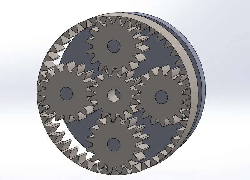
Finished Assembly-
Motion Analysis
For motion analysis, we consider three cases:
| Sl.No | Input | Output | Fixed |
| 1 | Sun Gear | Carrier | Ring Gear |
| 2 | Ring Gear | Carrier | Sun Gear |
| 3 | Sun Gear | Ring Gear | Carrier |
The input speed is 200rpm in all cases.
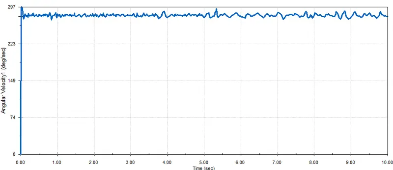
CASE 1:
Input: Sun gear
Output: Carrier
Fixed: Ring Gear
Plot:
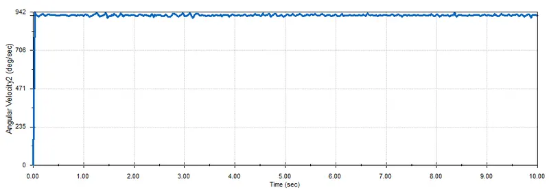
CASE 2:
Input: Ring Gear
Output: Carrier
Fixed: Sun Gear
Plot:
CASE 3:
Input: Sun Gear
Output: Ring Gear
Fixed: Carrier
Plot:
Observations and Conclusions:
In case 1, the planet gears rotate about their axis as well as roll about the inside of the ring gear. The angular velocity obtained in this case is 265-297 deg/sec.
In case 2, the planet gears rotate about their axis as well as rolls. The angular velocity obtained is this case 900-942 deg/sec. The angular velocity is high because the velocity ratio between the two gears is high.
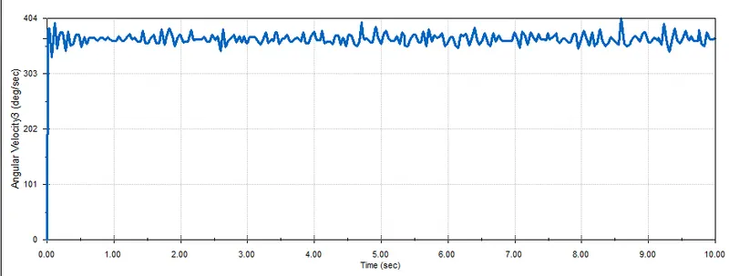
In case 3, the planet gear only rotates about axis. The angular velocity obtained is 320-404 deg/sec.
To obtain accurate readings, we can use precise contact for as the graph in case 3 shows alot of deviations.
Links for Animations:
Case1:https://youtu.be/dHoSNxNVxDk
Case2:https://youtu.be/W7DGZOKO6Lw
Case3: https://youtu.be/zRfT4CrcZHU
Google Drive Link:
https://drive.google.com/drive/folders/1HLB5EYkHmkC0-WTyyF9lBggpkN2edffd?usp=sharing