MBD simulation of Planetary gear
AIM:
To model and simulate a planetary gear train.
OBJECTIVE:
1)To model all the parts of the planetary gear.
2)To assemble all the parts and simulate it.
3)To plot various graphs.Compare and study from it.
THEORY:
What are Planetary Gears?
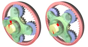
A planetary gear set is made up of three types of gears; a sun gear, planet gears, and a ring gear. The sun gear is located at the center , and transmits torque to the planet gears which are typically mounted on a moveable carrier . The planet gears orbit around the sun gear and mesh with an outer ring gear. Planetary gear systems can vary in complexity from very simple to intricate compound systems, depending on the application.
Planetary gears are often used when space and weight are an issue, but a large amount of speed reduction and torque are needed. This requirement applies to a variety of industries, including tractors and construction equipment where a large amount of torque is needed to drive the wheels. Other places you will find planetary gear sets include turbine engines, automatic transmissions, and even electric screwdrivers.
Planetary gear systems are able to produce a lot of torque because the load is shared among multiple planet gears. This arrangement also creates more contact surfaces and a larger contact area between the gears than a traditional parallel axis gear system. Because of this, in the load is more evenly distributed and therefore the gears are more resistant to damage.
The centre external spur gear is the sun gear. The large internal spur gear is the ring gear.The external spur gear between the ring gear and the sun gaer is the planet gear. The carrier is attached to the planet gear.
PROCEDURE:
1)Firstly,using the given input parameters the planet gear is designed.
2)All the parts of the planetary gear are modelled such as Sun gear, planet gear,ring gear and carrier.
3)All the parts are assembled and simulation is done for three cases.
| Sl.No | Input | Output | Fixed |
| 1 | Sun Gear | Carrier | Ring Gear |
| 2 | Ring Gear | Carrier | Sun Gear |
| 3 | Sun Gear | Ring Gear | Carrier |
4)Graphs are plotted for the above three cases for angular velocity with respect to time.The graphs are compared and studied.
CALCULATION OF PLANET GEAR:
1)DIAMETER:
Rr=Dp+Rs
Therefore, Dp=Rr-Rs
Dp=115/2-35/2=40mm
2)NO. OF TEETH:
D=m*t
Therefore, t=D/m=40/2.5=16
No. of teeth=16
MODELS:
1)SUN GEAR:
2)RING GEAR:
3)PLANET GEAR:
4)PLANETERY GEAR ASSEMBLY:
GRAPHS:
CASE 1:
Input-Sun gear, Output-carrier, Fixed-Ring gear
Here the planet gear not only rotates about its axis but also rotates inside of the ring gear along with the carrier. In this graph we can see that the angular velocity is between 235-313 deg/sec.
CASE 2:
Input-ring gear, Output-Carrier, Fixed-Sun gear
In this case the angular velocity achieved is high, this is because the internal gears are big and the planet gears are small which leads to a greater velocity ratio. The angular velocity is between 763-1017 deg/sec.
CASE 3:
Input-sun gear, Output-ring gear, Fixed-Carrier
In this case the angular velocity achieved is less. This is because the output is ring gear and the ring gear diameter is more which leads to low angular velocity. The angular velocity is between 302-402 deg/sec.
CONCLUSION:
Thus all the parts of planetary gear train are modelled and simulation is done. Graphs are plotted for three cases, compared and studied.