Modelling and simulation of a machine vice using Solidworks
AIM:
To model and simuate a machine vice using Solidworks.
OBJECTIVE:
1)To model the different parts of the machine vice.
2)To assemble the parts
3)To simulate the machine vice from 0-10 seconds.
4)To plot a graph between linear displacement and time.
THEORY:
A machine vice is a clamping device used to hold a workpiece securely when operating a machine tool, such as a drill press or milling machine. It differs from metalworking and woodworking vices as it is mounted to the table of a machine tool instead of a workbench.
A machine vice works by positioning and restraining a workpiece while using a machine such as a drill press or milling machine. ... When turned, pressure is exerted by this handle through the main screw, which either opens or closes the vice jaws depending on the direction of rotation.
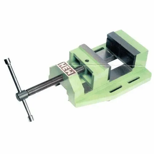
(image from google)
PROCEDURE:
1)Firstly, all the parts of the machine vice is modelled using Solidworks. Such as the fixed jaw, movable jaw, screw and the handle.
2)All the parts are assembled correctly.
3)Now the assembly is simulated for a time between 0-10 seconds.
4)From the simulation a graph is plotted between linear displacement with respect to time and the result is studied.
CAD MODELS OF ALL PARTS:
MACHINE VICE FIXED JAW:
MACHINE VICE MOVABLE JAW:
MACHINE VICE SCREW:
MACHINE VICE HANDLE:
SIMULATION OF MACHINE VICE:
I have attached the link below:
https://www.youtube.com/watch?v=kocStt5UpCg&feature=youtu.be
PLOT:
In this graph between linear displacement and time we can see that the graph is linearly propotional. It is because we have kept the motor at constant RPM.
RESULT:
Thus the machine vice is modelled, assembled, simulated and finally the graph is plotted and the results is discussed.