Photo Realistic Rendering
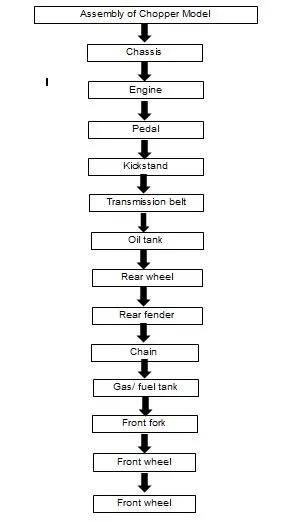
1. Assembly of Chopper Model
2. Objective- The main objective of the Project is to learn the basics of Part modelling, assembly of the parts created using CAD software- Solidworks and finally perform rendering & create photo-realistic views using Solidworks Photoview 360 and Solidworks Visualize.
3. Introduction- The designing of Chopper includes Solid Modelling & Surface modelling. The Parts modelled for American Chopper are:
- Transmission belt
- Kickstand
- Chain
- Rear Fender
- Rear Wheel
- Pedal
- Front Fender
- Front Wheel
- Oil tank
- Front Fork
- Chassis
- Engine
- Fuel tank
4. Design methodology-
Tools/ Features used in designing of Chopper model-
Feature Manager design tree:
It is located on left side of the SolidWorks window, it provides an outline view of the active part, assembly, or drawing.
Boss extrude:
A feature that adds material from a part.
Fillet:
An internal rounding of a corner or edge in a sketch, or an edge on a surface or solid
Appearances:
An appearance defines the visual properties of model including colour & texture
Spline:
It is used to create complex curves that have a continuously changed curvature.
Offset Entity:
One or more sketch entities, selected model edges, or model faces by specified distance.
Loft Boss:
It helps to generate complex boss by transitions between profiles.
Dome:
Select one or more planar or non- planar faces. For creating a semi- hemispherical shape.
Cut extrude:
A feature that removes material from a part.
Split:
It is used to project an entity onto other surfaces or curved/ planar faces. Also, we can split faces on multiple bodies with on command.
3-point Arc:
A curve line drawn with the help of 3 points.
Trim:
It is used to omit the unwanted edges, generally lines/ arcs.
Revolved boss:
A feature that creates boss by revolving one or more sketched profiles around a centreline.
Mirror:
(1) A mirror feature is a copy of a selected feature, mirrored about a plane or planar face. (2) A mirror sketch entity is a copy of a selected sketch entity that is mirrored about a centreline. If the original feature or sketch is modified, the mirrored copy is updated to reflect the change.
Extend:
It is used to add or perform extension of lines/ arcs.
Shell:
A feature that hollows out a part, leaving open the selected faces and thin walls on the remaining faces. A hollow part is created when no faces are selected to be open.
Circular pattern:
The circular parent bodies are used to create different number of instances required to create the pattern circularly.
Combine:
It helps to manually merge two bodies.
Chamfer:
Bevels a selected edge or vertex. It can apply chamfers to both sketches and features.
Linear pattern:
The linear parent bodies are used to create different number of instances required to create the pattern linearly.
Revolve cut:
A feature that creates a revolved cut by revolving one or more sketched profiles around a centreline.
Pierce relation:
Makes a sketch point coincident to the location at which an axis, edge, line, or spline pierces the sketch plane.
Projected curve:
It is a 3D curve which is projected using two different 2D sketches.
Composite curve:
It is a combination of two projected curves.
Surface Loft:
It helps to generate complex surface by transitions between profiles.
Surface knit:
It is used to reduce the gap/ knit the two surfaces.
Swept surface:
It creates a surface by moving a profile (section) along a path.
Swept cut:
It creates a cut by moving a profile (section) along a path.
Reference geometry:
Includes planes, axes, coordinate systems, and 3D curves. Reference geometry is used to assist in creating features such as lofts, sweeps, drafts, chamfers, and patterns.
Description of Parts and Features of Chopper Model-
1. Transmission belt:
A transmission belt is a loop of flexible material which are used to connect to pulleys/ shafts & for transmission of power.
Features used: Offset Entity, Boss extrude, Fillet, Changing apperances.
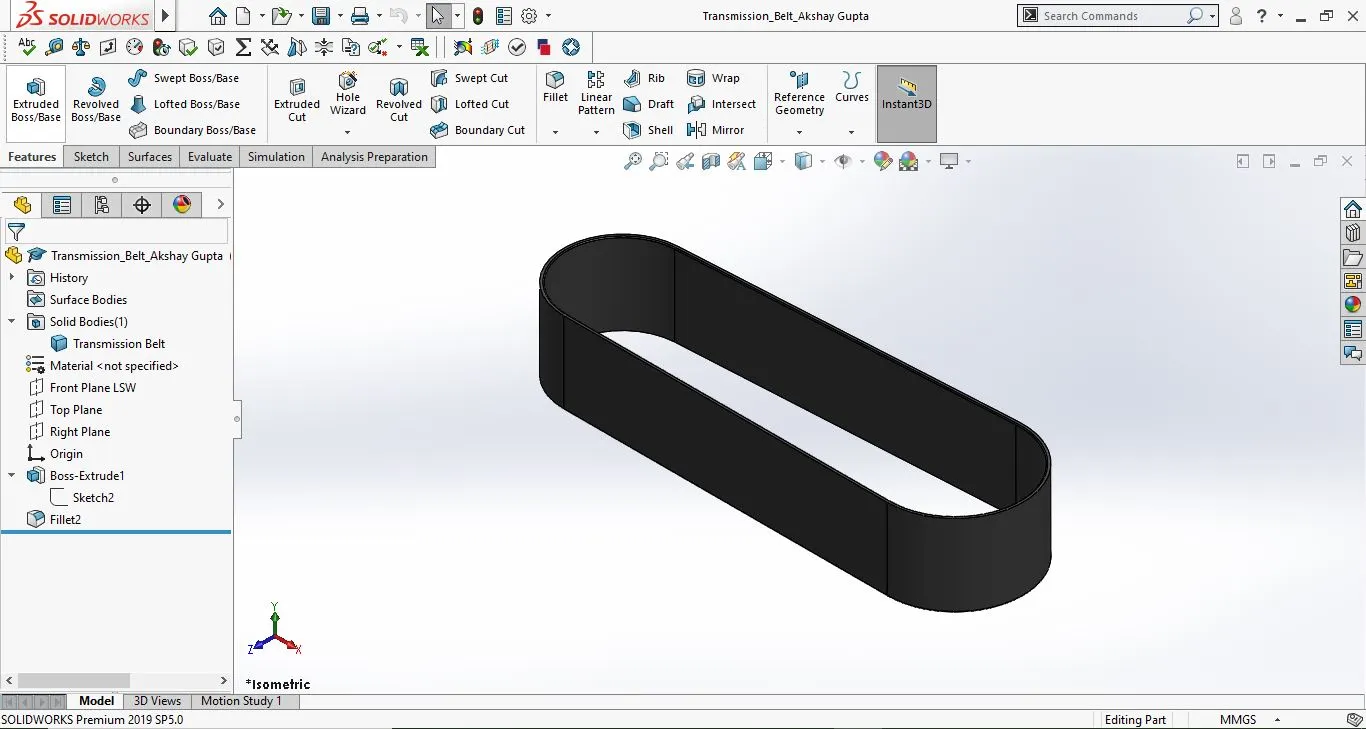
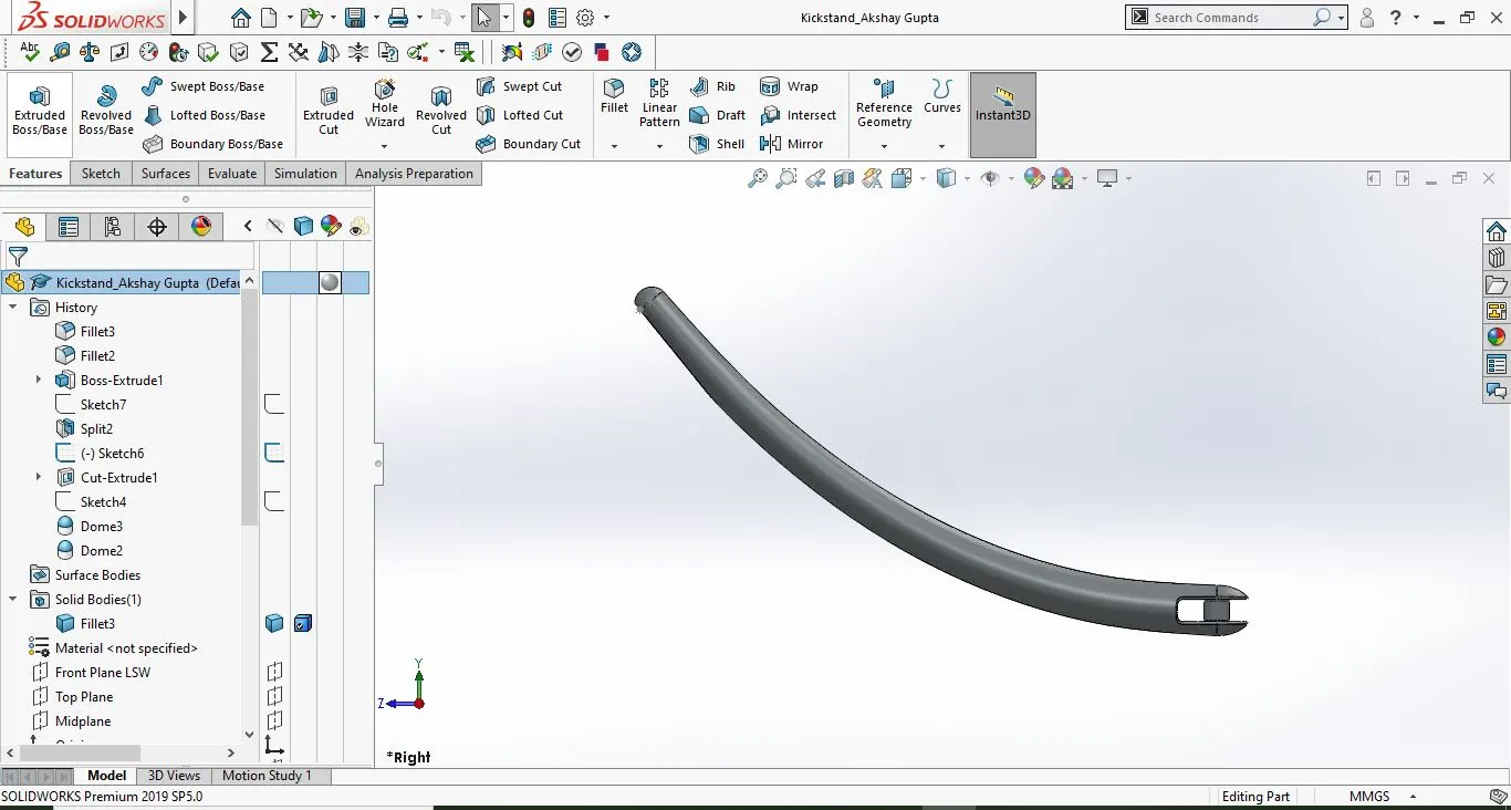
2. Kickstand:
A kickstand provides support to overall motorcycle by keeping it in vertical position without any help of a person. It is mounted on the frame of the motorcycle.
Features used: Spline, Loft Boss, Dome, Cut extrude, Split, Boss extrude, Fillet.
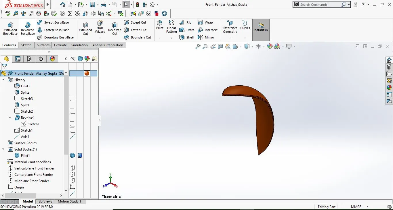
3. Front fender-
It is a part of a vehicle body that frames a wheel nicely. Its purpose is to prevent the tire to throw mud/ stone pieces in air. It is mounted on the front tire of the motorcycle.
Features used- 3-point Arc, Trim, Revolved boss, Fillet, Split, Dynamic mirror
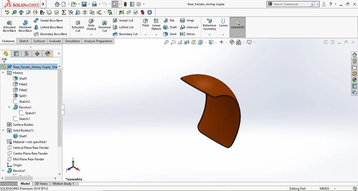
4. Rear fender:
It is a part of a vehicle body that frames a wheel nicely. Its purpose is to prevent the tire to throw mud/ stone pieces in air. It is mounted on the front tire of the motorcycle.
Features used: Offset entity, Extend, Trim, Revolved boss, Split, Fillet, Shell
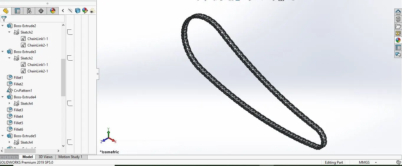
5. Chain:
A chain in motorcycles are connecting assembly of links mounted on sprocket & is used for power transmission from engine to Rear wheel.
Features used: Slot, Block, Boss extrude, Offset, Concentric, Curve pattern, Mirror, Fillet.
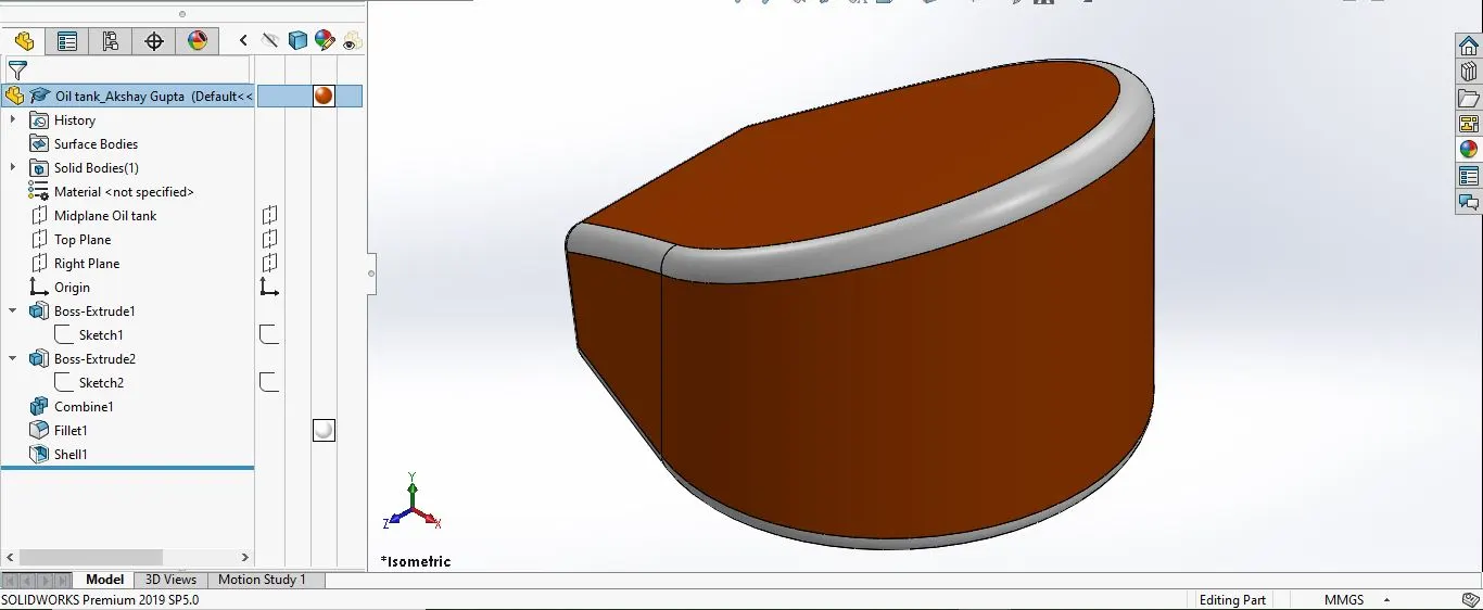
6. Oil tank:
It is used for storing lube oil for lubrication of engine parts.
Features used: Dynamic mirror, Spline, Boss extrude, Fillet, Shell, Combine.
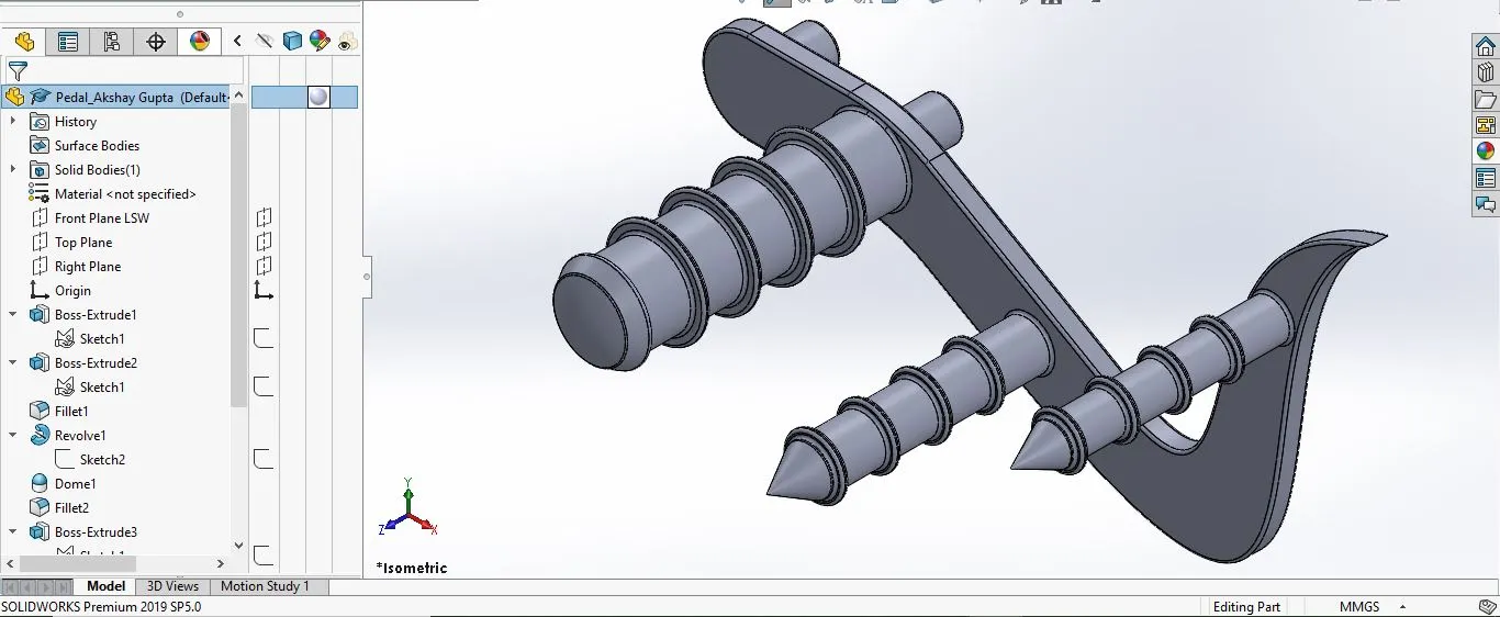
7. Pedal:
Pedal is a part of motorcycle used for shifting gears & also for resting the foot of rider.
Features used: Spline, Boss extrude, Revolve boss, Dome, Chamfer, Offset entity, Linear pattern, Fillet
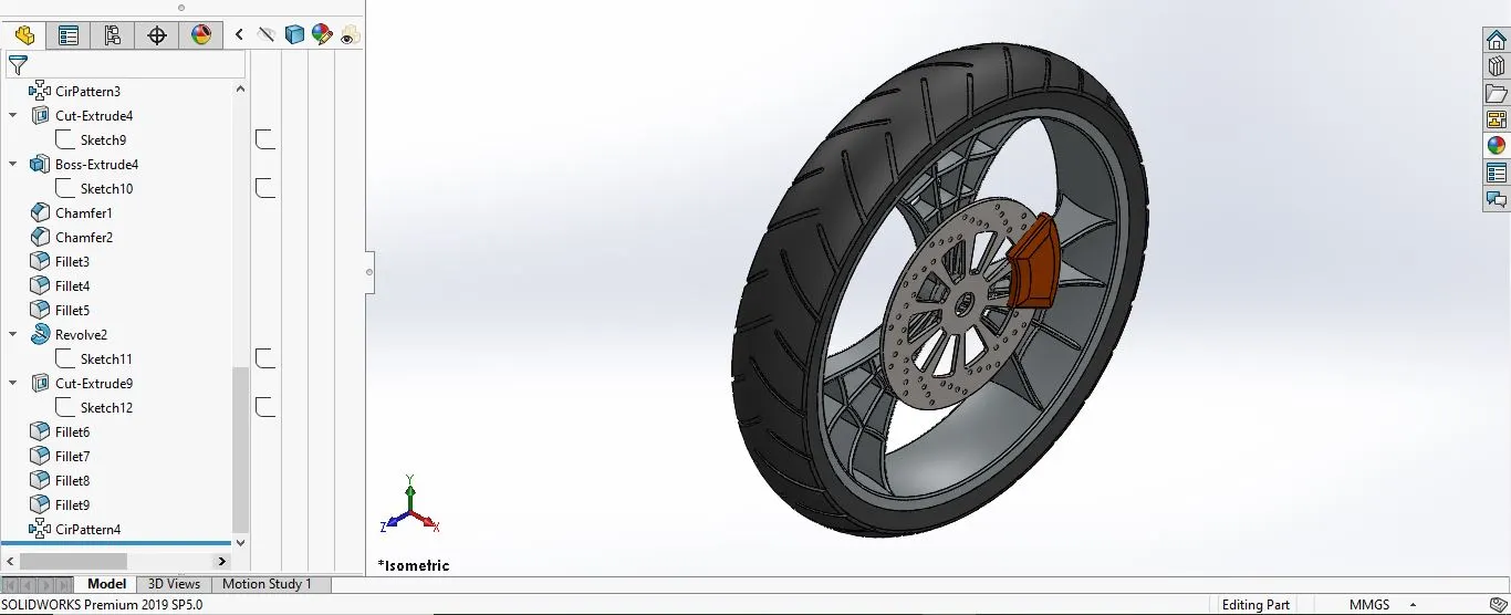
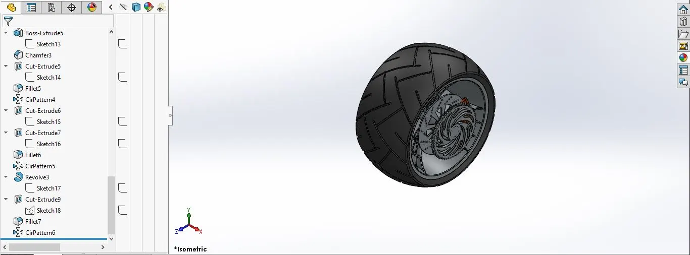
8. Front wheel:
A front wheel is a circular block of hard material (Rim) which is surrounded by rubber material tire at its circumference. The front wheel is mounted on Front fork.
Features used: Spline, Mirror, Boss extrude, Cut extrude, Revolve cut, Circular pattern, Combine, Fillet, Chamfer
9. Rear wheel:
A rear wheel is a circular block of hard material (Rim) which is surrounded by rubber material tire at its circumference. It is mounted on Hub of the chassis.
Features used: Boss extrude, Cut extrude, Revolved cut, Circular pattern, Combine, Fillet, Chamfer
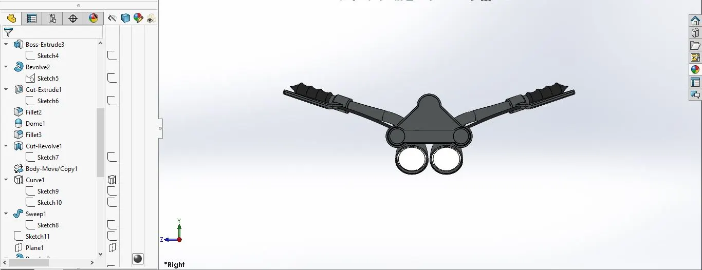
10. Front fork:
It is basically an assembly of handlebars, headlights & front wheel.
Features used: Boss extrude, Revolved boss, Extrude cut, Fillet, Dome, Revolve cut, Sweep, Project curve, Mirror, Combine.
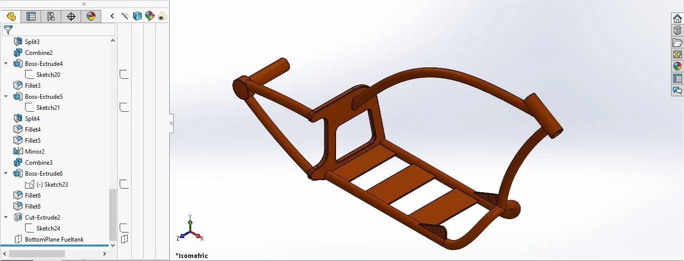
11. Chassis:
It is base structure of a vehicle & all the parts like Front fork, wheel, Engine, kickstand etc are assembled on it.
Features used: Project curve, Sweep, Mirror, Boss extrude, Fillet, Extrude cut, Dome, Combine, Chamfer, Split, Revolve boss
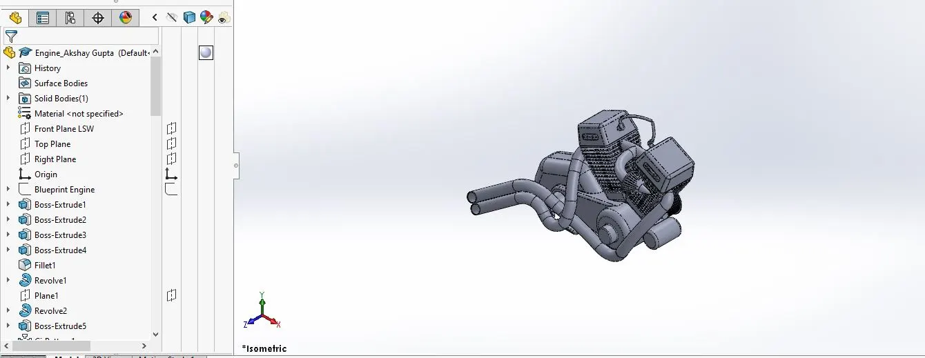
12. Engine:
It is a heart of an aut omobile which burns a fuel and generates power which is further transmitted to the wheel to create the required motion.
Features used: Boss extrude, Project curve, Sweep, Mirror, Boss extrude, Fillet, Extrude cut, Dome, Chamfer, Split, Revolve boss, Linear Pattern, Circular pattern, Composite curve.
13. Fuel tank:
It is a storage tank which stores fuel/ gas which is injected into an engine.
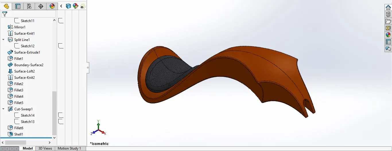
Features used: Surface Loft, Surface knit, Project Curve, Fillet, Swept surface, Split, Mirror, Swept cut, Reference geometry.
- Assembly of American Chopper model:
Assembly:
A document in which parts & features are mated together.
For example, in an assembly, an Oil tank can be mated to other parts, such as engine. The extension for a Solidworks assembly file name is .SLDASM.
Mate:
A geometric relationship, such as coincident, perpendicular, tangent, and so on, between parts in an assembly.
Suppress:
It removes an entity from the display and from any calculations in which it is involved. You can suppress features, assembly components, and so on. Suppressing an entity does not delete the entity; you can unsuppress the entity to restore it.
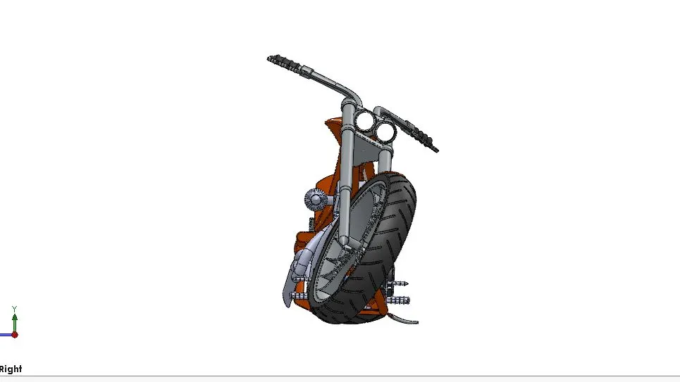
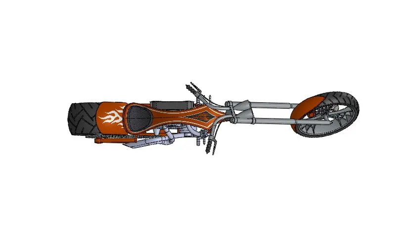
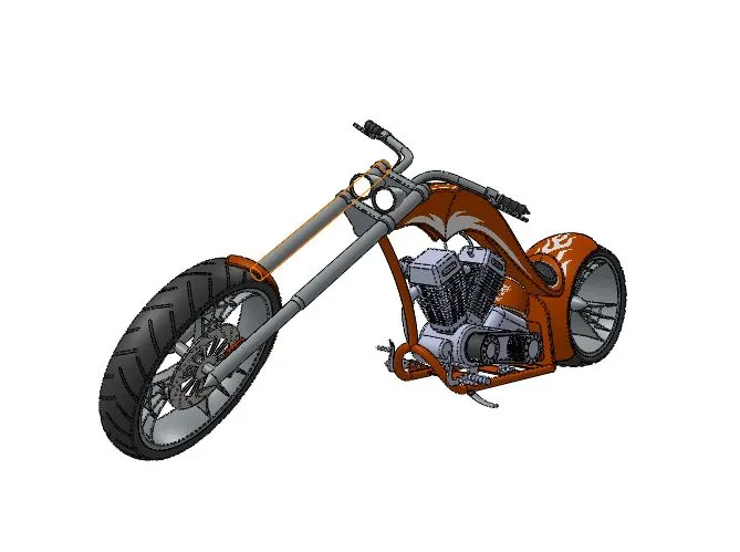
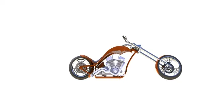
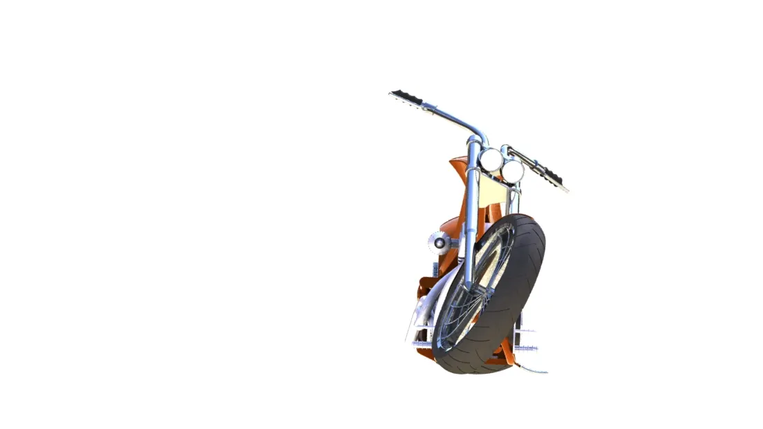
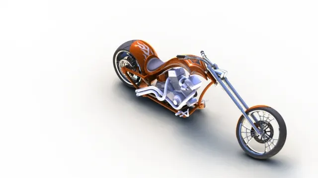
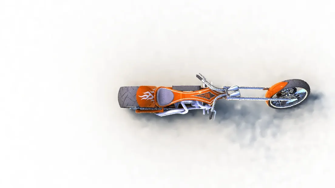
Various views of our model-
Front View
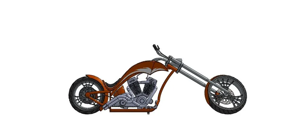
Side View
Isometric View
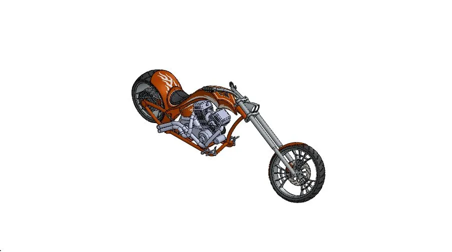
Top View
Camera setup View
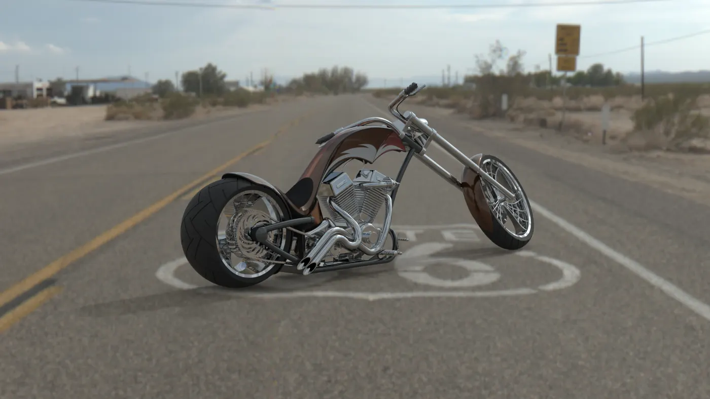
- Photo- realistic Rendering images:
Rendering helps to create photo-realistic images of SolidWorks models. The rendered image incorporates the appearances, lighting, scene, and decals included with the model.
In this project, we have used below mentioned Add-ins of Solidworks to create photo-realistic images-
- PhotoView 360
- Solidworks Visualize
Rendering images of an Assembly-
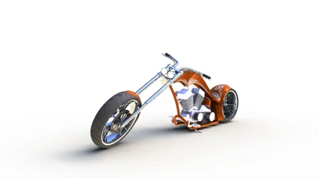
- Conclusion: In the designing of American Chopper, we have used –
- Various tools & features of SOLIDWORKS. With this, all the parts of Chopper are modelled.
- Further, Assembly of all the individual parts are done by mating them together in SOLIDWORKS.
- Finally, photo- realistic images are rendered using Photoview 360 & SOLIDWORKS Visualize.