Advanced Sheet Metal Design Using NX Cad Challenge_5_Odd Shaped Enclosure
- DESIGN OF ODD SHAPED ENCLOSURE
- Objective- The main objective of the Project is to design the ‘Odd Shaped Enclosure’ using required Tools & features of SIEMENS NX CAD.
- Introduction- The designing of the Odd Shaped Enclosure is done with the help of 3D CAD software NX CAD by Siemens. This software uses familiar technology and workflows & provides a complete set of tools to efficiently create the desired models.
In NX CAD, we have used Sheetmetal application. This application provides an environment for the design of sheet metal parts which are used in machinery, automotive, aerospace etc. NX sheet metal Design tools incorporate material & bending information, enabling the model to represent both the formed component & flattened blank shapes. Our model is created in ‘.prt’ extension.
Fundamental terminology related to Sheet metal designing-
Bending- It is a process in which a force is applied to sheel metal at a particular direction which causes it to bend at an angle and form the desired shape.
Bend radius- The distance from the bend axis to the inside surface of the material between the bend lines.
Bend line- The straight line on the surface of the sheet, on either side of the bend that defines the end level of the flange & start of the bend.
Bend angle- The angle of the bend measured between the bent flange & its original position.
Bend relief- When sheet metal makes a transition from a bend to a flat surface, or to another bend, it tends to rip and tear. To eliminate this, a bend relief is added so the edge of the sheet metal is perpendicular to the bend.
Bend height- The sheet metal bending height should be at least 2 times the thickness of the sheet metal plus the bending radius, that is, H ≥ 2t + R.
K-Factor- It is the ratio of the neutral axis to the material thickness. When metal is bent the top section is going to undergo compression and the bottom section will be stretched. The line where the transition from compression to stretching occurs is called the neutral axis.
- Design methodology-
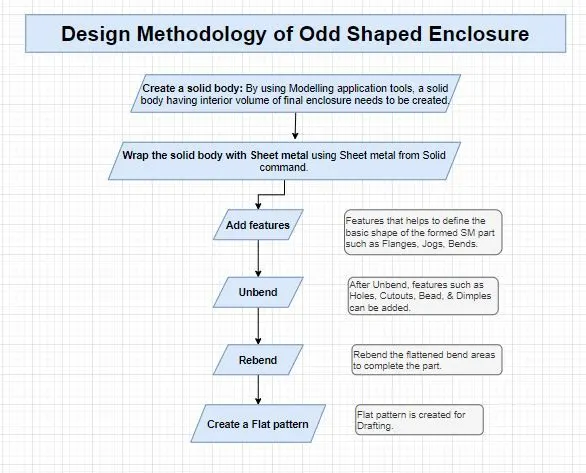
- Description of Tools/ Features used in designing Odd Shaped Enclosure-
Extrude- It creates a feature by extruding a section along a vector.
Sheet Metal from Solid- This feature is used to build a Sheet metal model that takes its shape from a collection of planar faces.
Flanges- Adds a flat flange at an angle to a planar face & adds the bend between two.
Jog- It helps to modify the model by lifting material on one side of sketch line , adding a flange between the two sides.
Unbend- Flattens a bend and add material adjacent to the bend.
Beads- Lifts material along the contour of a edge that simulates a stamping tool.
Hole- Adds a hole to one or more solid bodies in a part or assembly with options from counter bored, countersunk & threaded.
Rebend- Restores an unbend feature to its previous bend state, along with any features added after unbend feature.
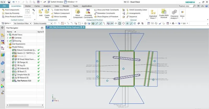
Flat pattern- Creates a flat pattern feature form formed Sheet metal part.
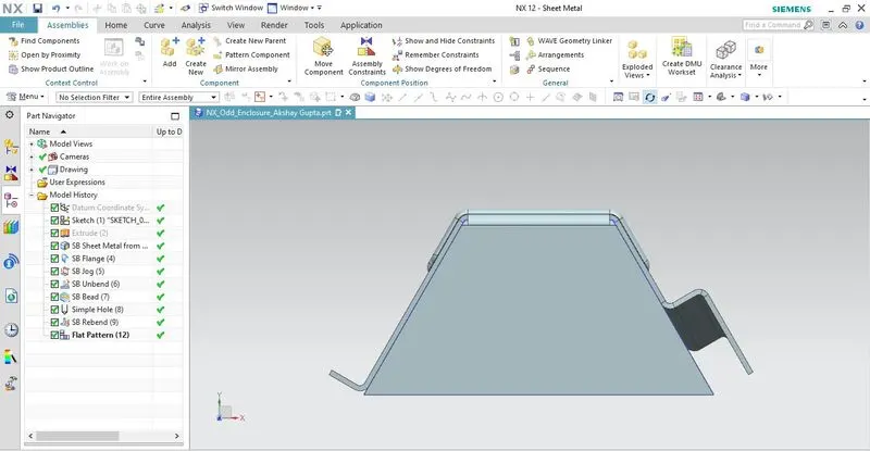
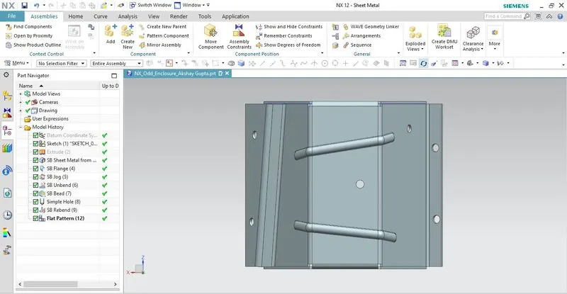
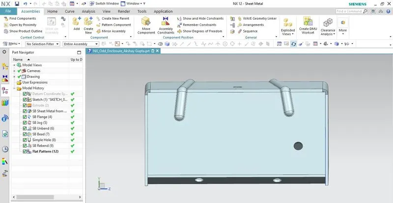
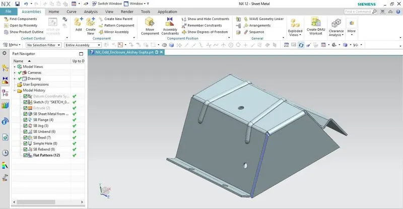
- Various views of Odd Shape Enclosure-
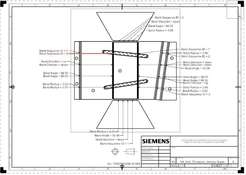
- Detailed drawing sheet:
- Conclusion:
- Hence, we have successfully designed Odd Shaped Enclosure using NX CAD.
- We have also learned fundamental features of NX Sheet metal environment like creating Sketch, Flanges, Bead, Holes, Bend, Rebend, Flat pattern etc.