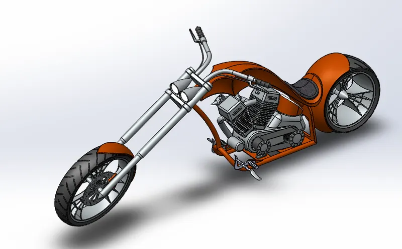
Photo Realistic Rendering
MODELLING & RENDERING OF AMERICAN CHOPPER
AIM:-
The Project Report is about the Designing, Modelling, and Photo Rendering of American Chopper using Solidworks 2021 and Solidworks Visualize 2021.
OBJECTIVE:-
To Design and model each component required to make assembly of an American Chopper in Solidworks and finally make a Photorealistic Rendering of the complete assembly of American Chopper. And to get a better insight of the features and tools which are used for modeling of the part and to know how exactly they work and also to get familiar with the user interface of the Solidworks.
Methodology:-
All the parts for the assembly of the chopper were made separately first and then were assembled in Solidworks
The flow of Action for Designing the Chopper:-
1. Part modeling of components of Chopper.
2. Assembly of designed components of Chopper.
3. Adding Scenes, Decal.
4. Photorealistic Rendering.
Different components of the American Chopper:-
1. Transmission Belt
2. Kickstand
3. Front Fender
4. Rear Fender
5. Front Wheel
6. Rear Wheel
7. Chain
8. Oil Tank
9. Gas Tank
10. Engine
11. Chassis
12. Pedal
13. Front Fork
COMMANDS USED TO DESIGN THE COMPONENTS OF AMERICAN CHOPPER:-
Line: This feature allows us to create a straight line. The line could be solid or constructed.
Circle:- This feature allows us to create a circle.
Arc:- This command help us to create an arc.
Rectangle:- This feature allows us to create Squares or rectangles.
Spline:- This command allows us to create a curved line.
Curve Projection:- This is used for the projection of the curves made in different planes to
create an intersected curve.
Split:- This feature is used to split bodies using a 2D sketch.
operation to succeed. The resulting Curve feature is listed in the Feature list and the curve
itself is listed in the Parts list (when selecting a curve, use the Parts list).
Trim:- This command is used to trim the sketches. You can use Power trim to trim multiple,
adjacent sketch entities by dragging the pointer across each sketch entity.
Extend:- This feature allows us to extend the sketches.
Extrude Boss:- This command is used to create solid bodies.
Extrude Cut:- This feature allows us to cuts any shape in the solid bodies.
Swept Boss:- Sweep creates a base, boss, cut, or surface by moving a profile (section)
along a path. A sweep can be simple or complex.
Mirror:- This feature allows us to create an exact copy of the solid body using a reference
plane or face.
Revolve:- Revolves add or remove material by revolving one or more profiles around a
centerline. You can create revolved boss/bases, revolved cuts, or revolved surfaces. The
revolving feature can be a solid, a thin feature, or a surface.
Linear Pattern:- This feature allows us to create a pattern in a straight line.
Circular Pattern:- This feature allows us to create a pattern in a circular path.
Fillet:- This is creating a rounded internal or external face on the part. We can fillet all
edges of a face, selected sets of faces, selected edges, or edge loops.
Chamfer:- This is used to create an inclined edge.
Plane:- This feature is to create a new reference plane.
Loft:- Loft creates a feature by making transitions between profiles. Aloft can be a base,
boss, cut, or surface. We create a loft using two or more profiles. Only the first, last, or first
and last profiles can be points. All sketch entities, including guide curves and profiles, can
be contained in a single 3D sketch.
Dome:- This feature allows us to create a dome shape on one or more faces on the same
model.
Shell:- The Shell definition is used to defining the thickness of thin shell elements.
Convert Entities:- You can create one or more curves in a sketch by projecting an edge,
loop, face, curve, or external sketch contour, set of edges, or set of sketch curves onto the
sketch plane.
Mirror Entities:- This command is used to mirror the 2D elements or sketch about the axis
or plane.
Surface Trim:- We can use a surface, plane, or sketch as trim intersecting surfaces. You
can also use a surface in conjunction with additional surfaces, as mutual trim tools.
Surface Knit:- This feature is used to combine two or more faces and surfaces into one.
Filled Surface:- This feature constructs the surface patch with any number of sides, within
the boundary defined by existing model edges, sketches, or curves, including composites
curves.
Ruled Surface:- This feature is used to obtain the extruded surface perpendicular to the
plane and can be tilted at a certain angle.
Rollback:- We can add new features or edit existing features while the model is in the
rolled-back state. We can save models with the rollback bar placed anywhere.
Delete/Keep Body:- This feature is very helpful when we working with multibody parts. We
can select bodies to keep or delete by using the Delete/Keep body feature.
Combine Tool:- In a multibody part, you can combine multiple solid bodies to create a
single-bodied part or another multibody part. You can add or subtract bodies, or keep
material that is common to the selected bodies.
ADD:- Combines solids of all selected bodies to create a single body
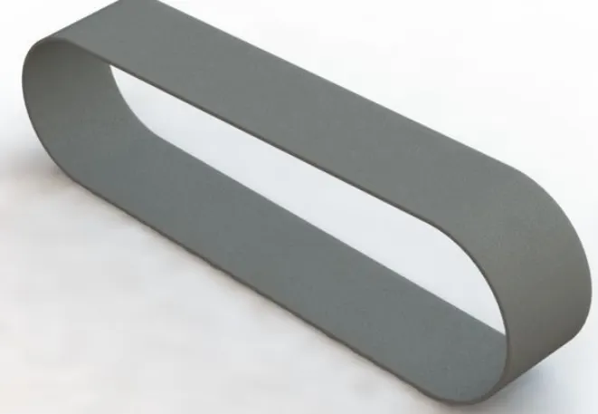
1.) Transmission Belt:-
Feature Tool:- Extruded boss/base and fillet
Sketch Tool:- Line, arc, and offset entities.
Appearance:- Matte Rubber.
The rendered image is given below:-
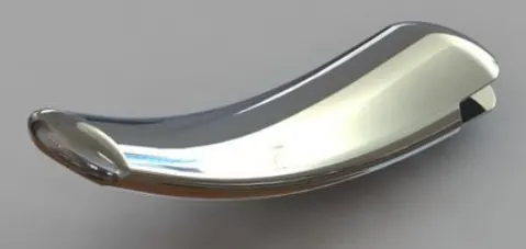
2.) Kickstand:-
Feature Tool:- Extruded boss/base, Loft Boss/Base, Extruded Cut, and Pierce
Sketch Tool:- Rectangle, Circle, Spline, and Ellipse.
Appearance:- Chrome Steel.
The rendered image is given below:-
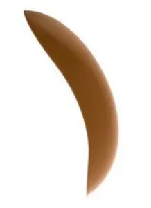
3.) Front Fender:-
Feature Tool:- Fillet, Revolve Boss/Base, and Split.
Sketch Tool:- Spline, Three-point arc, and Line.
Appearance:- Painted Siena.
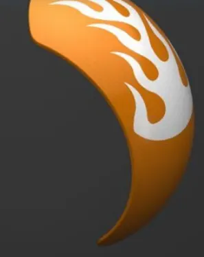
The rendered image is given below:-
4.) Rear Fender:-
Feature Tool:- Fillet, Revolve Boss/Base, Shell, and Split.
Sketch Tool:- Spline, Three-point arc, Offset Entities, and Line.
Appearance:- Painted Siena.
The rendered image is given below:-
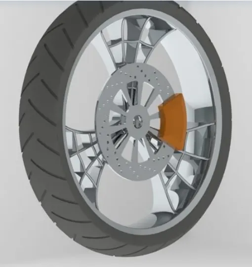
5.) Front Wheel:-
Feature Tool:- Fillet, Revolve Boss/Base, Chamfer, Extruded Boss/Base, Revolve Cut, Circula
Pattern, Linear Pattern, and Mirror.
Sketch Tool:- Spline, Three-point arc, Line, Rectangle, Convert Entities, Offset Entities, Trim Entities, and Circle.
Appearance:- Painted Siena for Caliper, Chrome Steel for Rim, Matte Rubber for Tire.
The rendered image is given below:
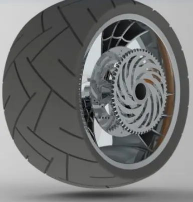
6.) Rear Wheel:-
Feature Tool:- Fillet, Revolve Boss/Base, Chamfer, Extruded Boss/Base, Revolve Cut, Circula Pattern, Linear Pattern, and Mirror.
Sketch Tool:- Spline, Three-point arc, Line, Rectangle, Convert Entities, Offset Entities, Trim Entities, and Circle.
Appearance:- Painted Siena for Caliper, Chrome Steel for Rim, Matte Rubber for Tire.
The rendered image is given below:
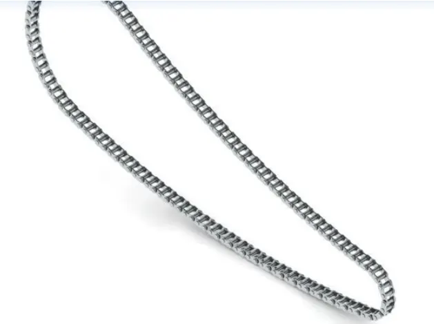
7.) Chain:- Chain acts as a connecting bridge between the Engine and Rear Wheel which helps in transmitting power.
Feature Tool:- Fillet, Extruded Boss/Base, Mirror, Block, Delete/Keep Body, and Curve Driven Pattern.
Sketch Tool:- Straight Slots, Three-point arc, Circle, and Line.
Appearance:- Chrome Steel.
The rendered image is given below:-
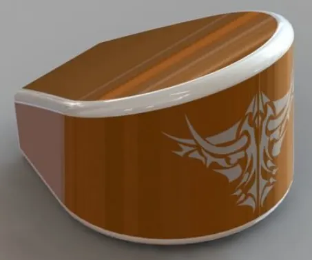
8.) Oil Tank:-
Feature Tool:- Fillet, Shell, Combine, and Extruded Boss/Base.
Sketch Tool:- Spline, Circle, and Line.
Appearance:- Painted Siena.
The rendered image is given below:-
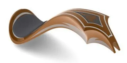
9. Gas Tank
Cut, Shell, and Boundary Surface.
Sketch Tool:- Spline, Circle, Convert Entities, Offset Entities, and Line.
Appearance:- Painted Siena for Gas Tank and Fabric for Driver Seat.
The rendered image is given below:-
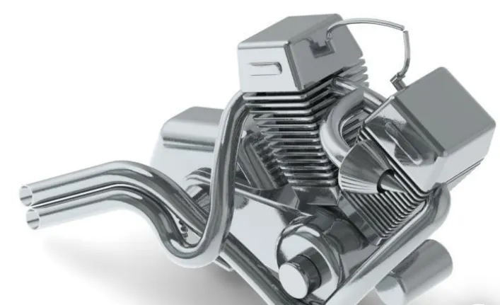
10.) Engine:-
Feature Tool:- Fillet, Extruded Boss/Base, Dome, Extruded Cut, Revolved Cut, Composite Curves, Projected Curves, Swept Boss/Base, Revolve Boss/Base, Chamfer, Mirror, and Combine.
Sketch Tool:- Spline, Circle,3-Point Arc, Convert Entities, Offset Entities, and Line.
Appearance:- Chrome Plate.
The rendered image is given below:-
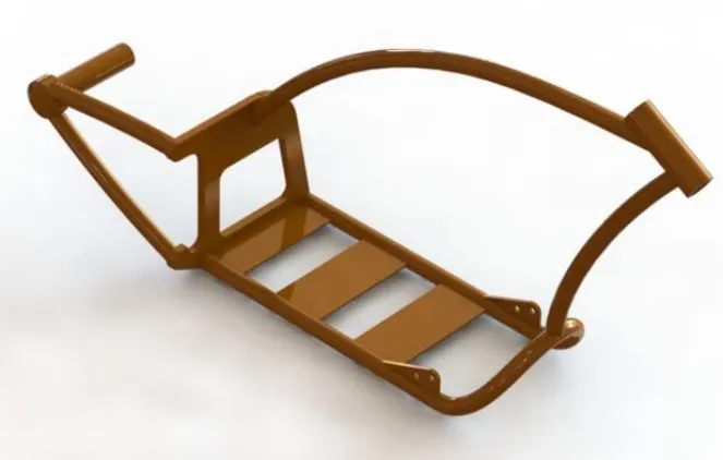
11.) Chassis:-
Feature Tool:- Split, Plane, Fillet, Extruded Boss/Base, Dome, Extruded Cut, Revolved Cut,
Composite Curves, Projected Curves, Swept Boss/Base, Revolve Boss/Base, Chamfer, Mirror
and Combine.
Sketch Tool:- Spline, Circle,3-Point Arc, Convert Entities, Offset Entities, and Line.
Appearance:- Painted Siena.
The rendered image is given below:-
12.) Pedal:-
Feature Tool:- Fillet, Revolve Boss/Base, Extruded Boss/Base, Dome, Linear Pattern, and Chamfer.
Sketch Tool:- Spline, Circle, and Line.
Appearance:- Chrome Plate.
The rendered image is given below:
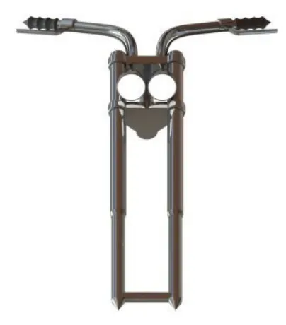
13.) FRONT FORK:-
Feature Tool:- Plane, Fillet, Extruded Boss/Base, Extruded Cut, Revolved Cut, Composite Curves, Projected Curves, Swept Boss/Base, Revolve Boss/Base, Chamfer, Mirror, and Combine.
Sketch Tool:- Spline, Circle,3-Point Arc, Convert Entities, Offset Entities, and Line.
Appearance:- Chrome Plate for Fork, Matte Rubber for handle and Brake Wire, and for Aria
Light for Lamp.
The rendered image is given below:-
ASSEMBLY OF THE AMERICAN CHOPPER:-
1. All the parts which are designed in the parts file are to be inserted into the assembly file
one by one as per the requirements.
2. And then apply mates to each individual part with other parts for proper alignment.