Photo Realistic Rendering
- Assembly of Chopper Model
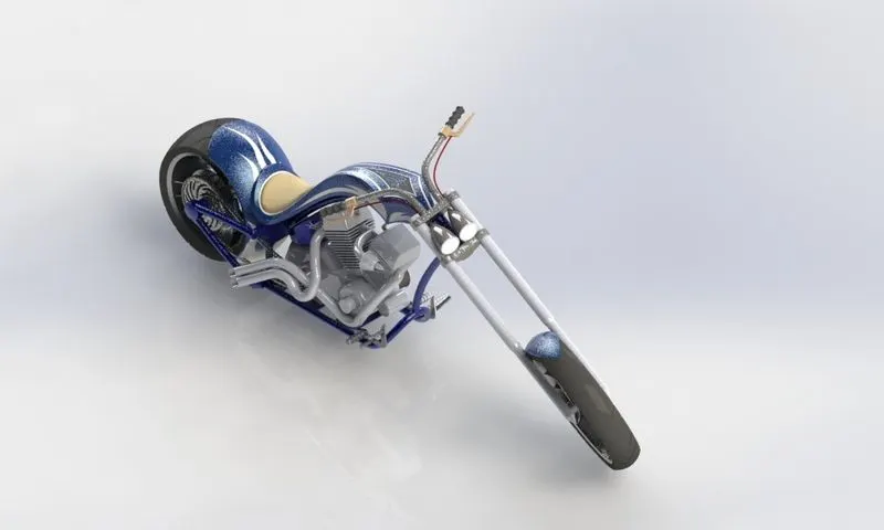
- Objective -
- To design individual parts of the chopper with fully defined sketches and appropriate appearances.
- To assemble all the individual parts of the chopper model by assigning suitable constraints.
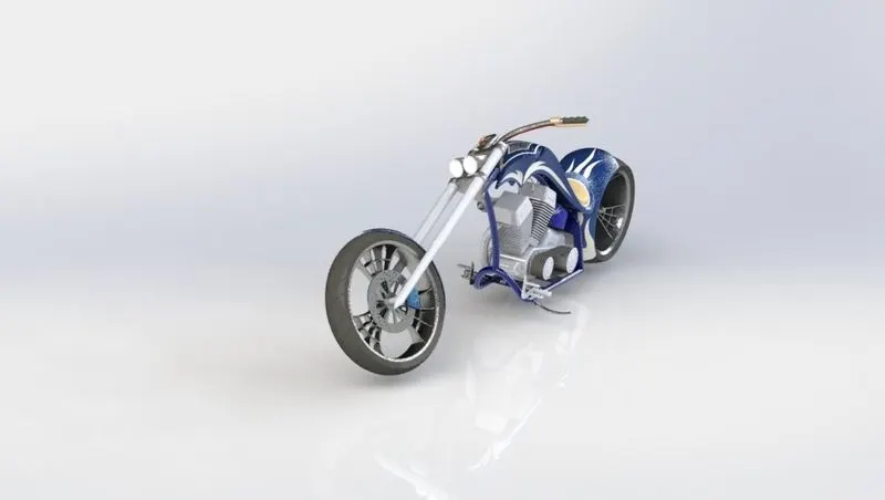
- To render the chopper model by adding appearances, decals, lights, cameras, and background scenes.
- Introduction -
Chopper is a customized bike which has a powerful engine and simple parts with high precise shapes and edges. PARTS TO BE MODELLED IN CHOPPER:
- Transmission Belt
- Kick Stand
- Front Fender
- Rear Fender
- Oil Tank
- Chain
- Pedal
- Front Wheel
- Rear Wheel
- Front Fork
- Chassis
- Engine
- Gas Tank
- Design methodology/approach -
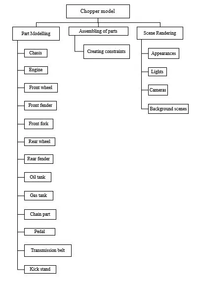
- Description along with the images of Part files -
Chassis:
Front view
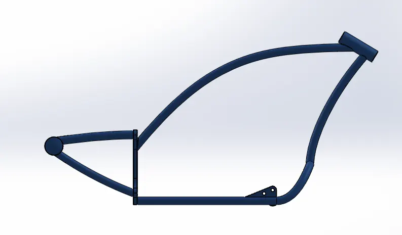
Side view
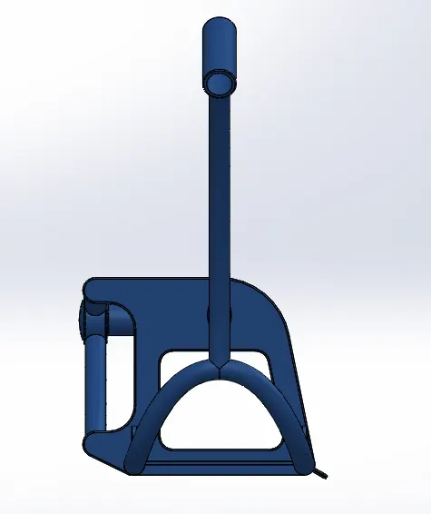
Isometric view
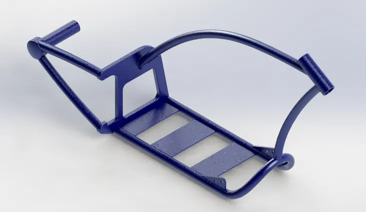
Tools & Features used:
Sketch picture: To insert pictures for reference
Sketch: To create required sketches
Line: To drawing lines and construction lines
Circle: To draw circles
Spline: To draw curves through interpolation of points
Intersection curve: To get an intersection curve obtained from projection of two curves
Boss-sweep: To obtain a solid body along the profile path
Boss-Extrude: To obtain 3d solid from 2d sketch
Cut-Extrude: To subtract a solid portion from a solid using 2d sketch
Reference plane: To construct a reference plane if existed references are not suitable or far away
Mirror: To mirror features or sketches along the selected reference
Split: To separate or split solid bodies
Combine: To combine or merge solid bodies
Dome: To create dome surfaces on flat surfaces
Fillet: To convert sharp internal or external edges into smooth or round edges
Chamfer: To convert sharp edges into bevel edges
Smart dimensions: To add or edit dimensions of sketches
Engine:
Front view
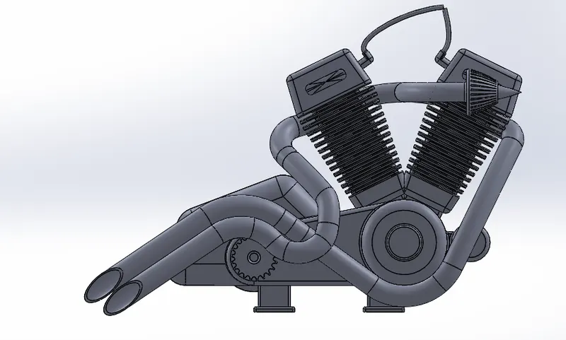
Isometric view
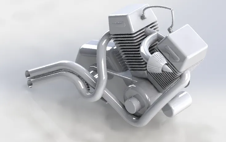
Tools & Features used:
Sketch picture: To insert pictures for reference
Sketch: To create required sketches
Line: To drawing lines and construction lines
Circle: To draw circle
Arc: To draw arc
Spline: To draw curves through interpolation of points
Convert Entities: To convert edges or curves into lines
Intersection curve: To get an intersection curve obtained from projection of two curves
Boss-sweep: To obtain a solid body along the profile path
Boss-Extrude: To obtain 3d solid from 2d sketch
Boss-Revolve: To revolve 2d sketch along the reference to obtain solid body
Cut-Extrude: To subtract a solid portion from a solid using 2d sketch
Reference plane: To construct a reference plane if existed references are not suitable or far away
Mirror: To mirror features or sketches along the selected reference
Split: To separate or split solid bodies
Combine: To combine or merge solid bodies
Dome: To create dome surfaces on flat surfaces
Fillet: To convert sharp internal or external edges into smooth or round edges
Chamfer: To convert sharp edges into bevel edges
Circular pattern: To create a pattern of feature or body along a circular reference
Linear Pattern: To create a pattern of feature or body along a linear reference
Composite curve: To obtain combined composite curve from two or more curves
Smart dimensions: To add or edit dimensions of sketches
Front wheel:
Front view
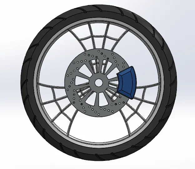
Side view
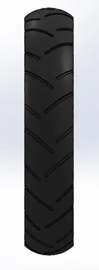
Isometric view
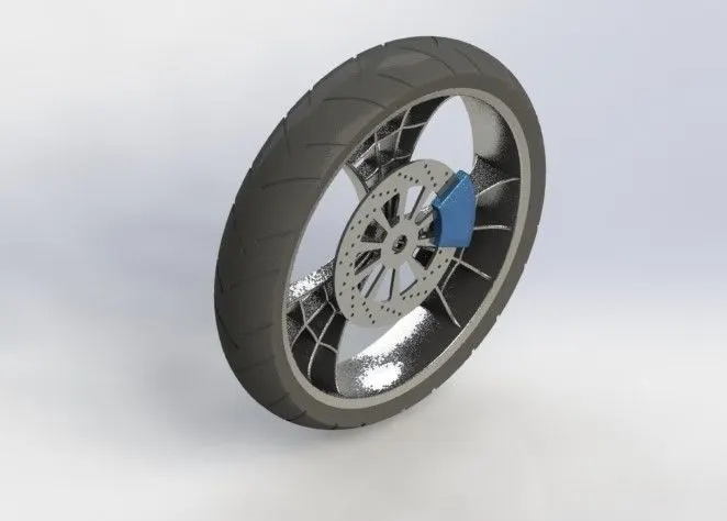
Tools & Features used:
Sketch: To create required sketches
Line: To drawing lines and construction lines
Circle: To draw circles
Arc: To draw arc
Spline: To draw curves through interpolation of points
Convert Entities: To convert edges or curves into lines
Offset Entities: To offset edges or lines to duplicate the edges
Boss-Extrude: To obtain 3d solid from 2d sketch
Boss-Revolve: To revolve 2d sketch along the reference to obtain solid body
Cut-Extrude: To subtract a solid portion from a solid using 2d sketch extrusion
Cut-Revolve: To subtract a solid portion from a solid using 2d sketch revolve
Combine: To combine or merge solid bodies
Fillet: To convert sharp internal or external edges into smooth or round edges
Chamfer: To convert sharp edges into bevel edges
Circular pattern: To create a pattern of feature or body along a circular reference
Linear Pattern: To create a pattern of feature or body along a linear reference
Smart dimensions: To add or edit dimensions of sketches
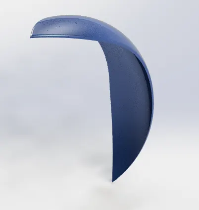
Front fender:
Front view
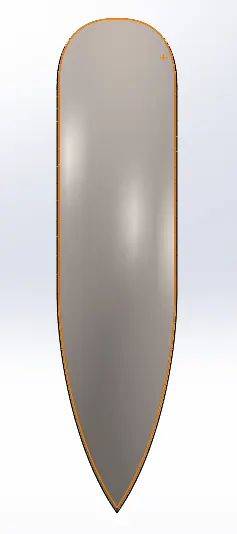
Side view
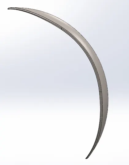
Isometric view
Tools & Features used:
Sketch: To create required sketches
Line: To drawing lines and construction lines
Spline: To draw curves through interpolation of points
Split: To separate or split solid bodies
Fillet: To convert sharp internal or external edges into smooth or round edges
Boss-Revolve: To revolve 2d sketch along the reference to obtain solid body
Smart dimensions: To add or edit dimensions of sketches
Rear wheel:
Front view
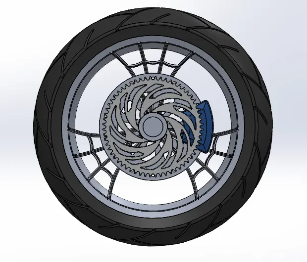
Side view
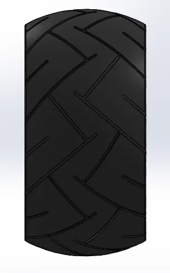
Isometric view
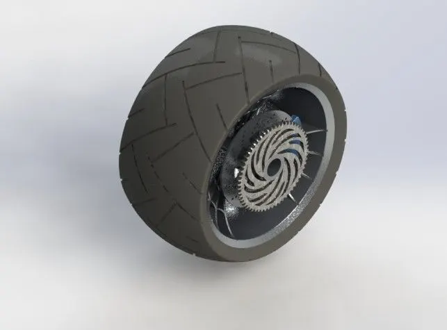
Tools & Features used:
Sketch: To create required sketches
Line: To drawing lines and construction lines
Spline: To draw curves through interpolation of points
Convert Entities: To convert edges or curves into lines
Offset Entities: To offset edges or lines to duplicate the edges
Boss-Extrude: To obtain 3d solid from 2d sketch
Boss-Revolve: To revolve 2d sketch along the reference to obtain solid body
Cut-Extrude: To subtract a solid portion from a solid using 2d sketch extrusion
Cut-Revolve: To subtract a solid portion from a solid using 2d sketch revolve
Combine: To combine or merge solid bodies
Fillet: To convert sharp internal or external edges into smooth or round edges
Chamfer: To convert sharp edges into bevel edges
Circular pattern: To create a pattern of feature or body along a circular reference
Linear Pattern: To create a pattern of feature or body along a linear reference
Smart dimensions: To add or edit dimensions of sketches
Rear fender:
Front view
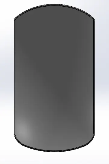
Side view
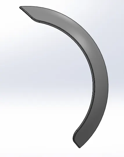
Isometric view
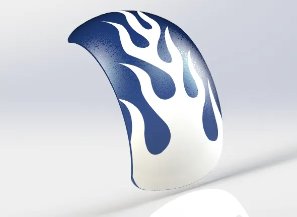
Tools & Features used:
Sketch: To create required sketches
Line: To drawing lines and construction lines
Spline: To draw curves through interpolation of points
Split: To separate or split solid bodies
Fillet: To convert sharp internal or external edges into smooth or round edges
Boss-Revolve: To revolve 2d sketch along the reference to obtain solid body
Smart dimensions: To add or edit dimensions of sketches
Oil tank:
Front view
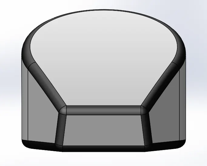
Side view
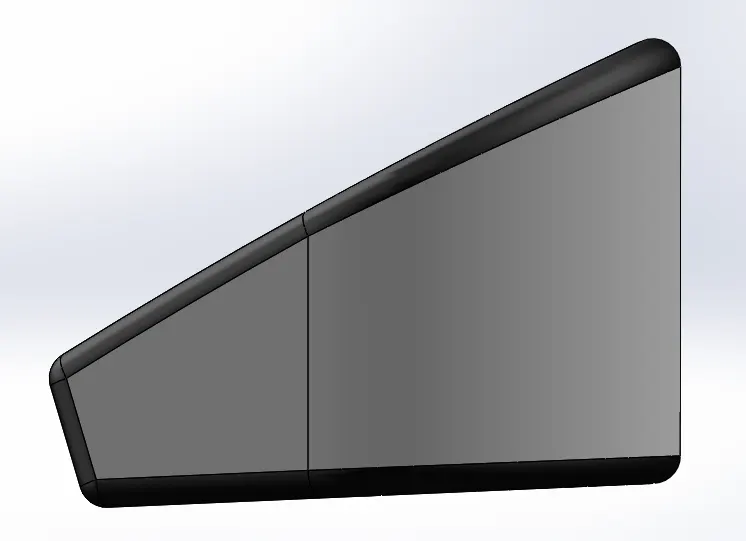
Isometric view
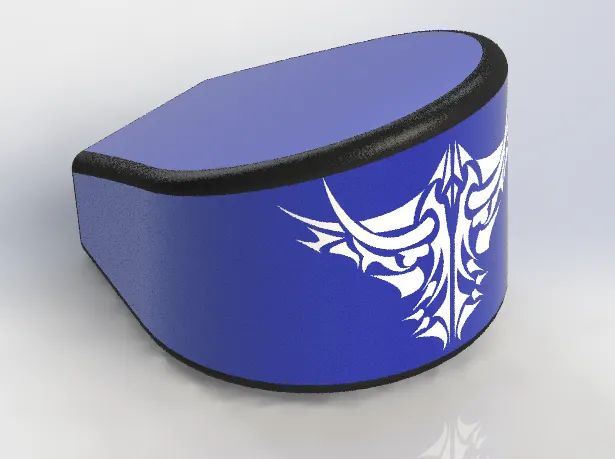
Tools & Features used:
Sketch: To create required sketches
Line: To drawing lines and construction lines
Spline: To draw curves through interpolation of points
Split: To separate or split solid bodies
Fillet: To convert sharp internal or external edges into smooth or round edges
Boss-Extrude: To obtain 3d solid from 2d sketch
Combine: To combine or merge solid bodies
Shell: To convert solid bodies into shells
Smart dimensions: To add or edit dimensions of sketches
Gas tank:
Front view
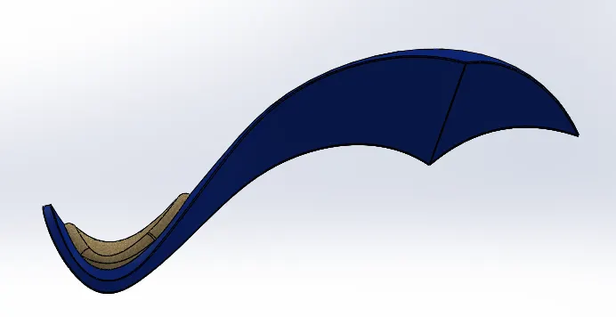
Side view
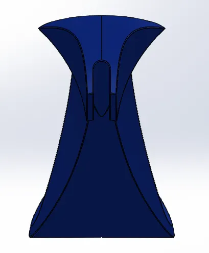
Isometric view
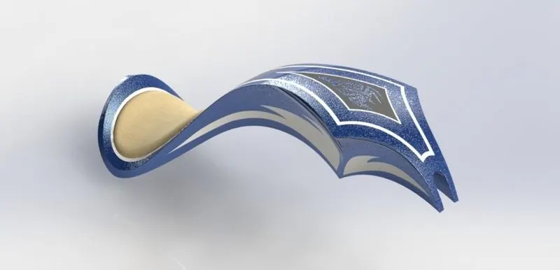
Tools & Features used:
Sketch picture: To insert pictures for reference
Sketch: To create required sketches
Line: To drawing lines and construction lines
Spline: To draw curves through interpolation of points
Split: To separate or split solid bodies
Fillet: To convert sharp internal or external edges into smooth or round edges
Boss-Extrude: To obtain 3d solid from 2d sketch
Reference plane: To construct a reference plane if existed references are not suitable or far away
Surface-loft: To create surface along the profiles
Surface-knit: To combine adjacent non intersecting features
Surface-sweep: To sweep along the sketch to obtain surface
Boundary-surface: To create surface from closed profile
Cut-sweep: To cut the surface along the profile through sweep along the reference
Shell: To convert solid bodies into shells
Mirror: To mirror features or sketches along the selected reference
Smart dimensions: To add or edit dimensions of sketches
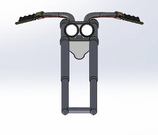
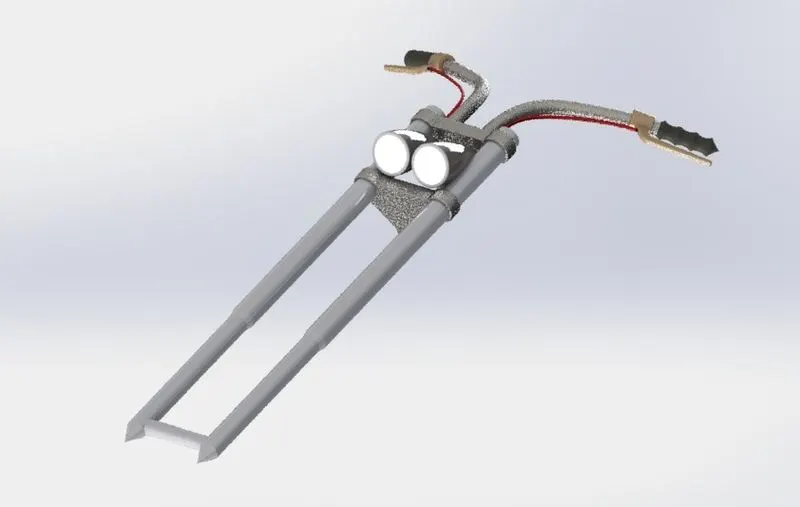
Front fork:
Front view
Top view 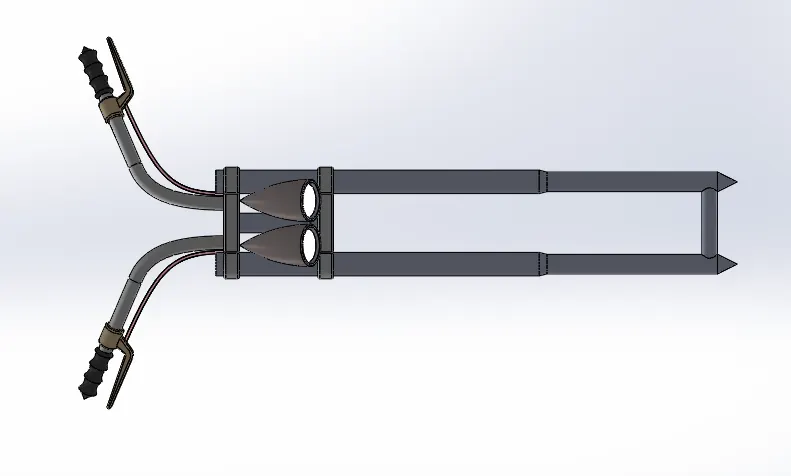
Isometric view
Tools & Features used:
Sketch: To create required sketches
Line: To drawing lines and construction lines
Circle: To draw circle
Arc: To draw arc
Spline: To draw curves through interpolation of points
Convert Entities: To convert edges or curves into lines
Intersection curve: To get an intersection curve obtained from projection of two curves
Boss-sweep: To obtain a solid body along the profile path
Boss-Extrude: To obtain 3d solid from 2d sketch
Boss-Revolve: To revolve 2d sketch along the reference to obtain solid body
Cut-Extrude: To subtract a solid portion from a solid using 2d sketch
Reference plane: To construct a reference plane if existed references are not suitable or far away
Mirror: To mirror features or sketches along the selected reference
Combine: To combine or merge solid bodies
Dome: To create dome surfaces on flat surfaces
Fillet: To convert sharp internal or external edges into smooth or round edges
Linear Pattern: To create a pattern of feature or body along a linear reference
Smart dimensions: To add or edit dimensions of sketches
Chain part:
Front view
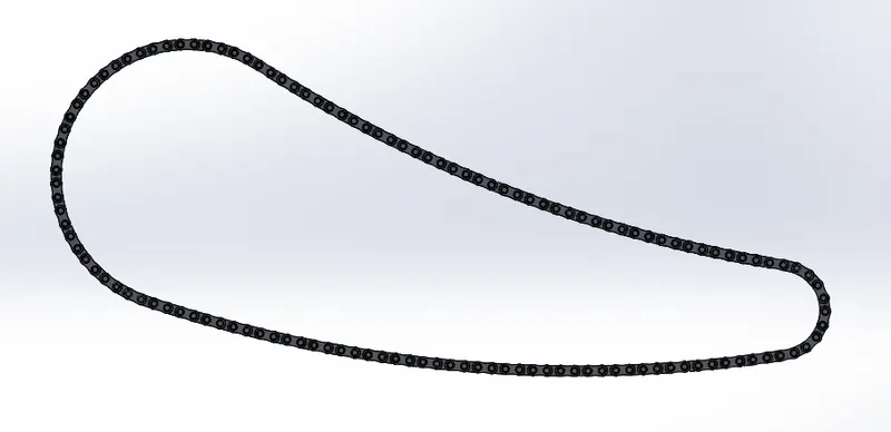
Isometric view
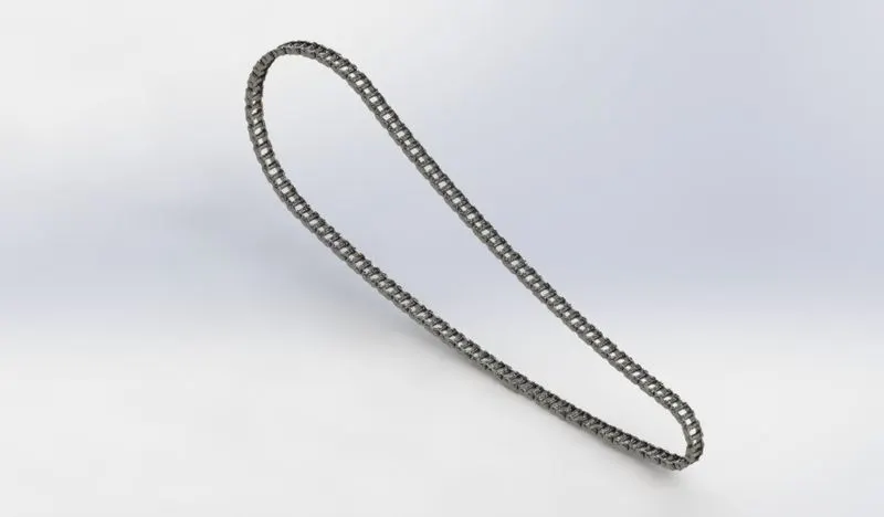
Tools & Features used:
Sketch: To create required sketches
Line: To drawing lines and construction lines
Circle: To draw circle
Arc: To draw arc
Spline: To draw curves through interpolation of points
Block: To create separate and save sketch from the existing sketch
Boss-Extrude: To obtain 3d solid from 2d sketch
Mirror: To mirror features or sketches along the selected reference
Combine: To combine or merge solid bodies
Fillet: To convert sharp internal or external edges into smooth or round edges
Curve Pattern: To create a pattern of feature or body along a curved reference
Smart dimensions: To add or edit dimensions of sketches
Pedal:
Front view
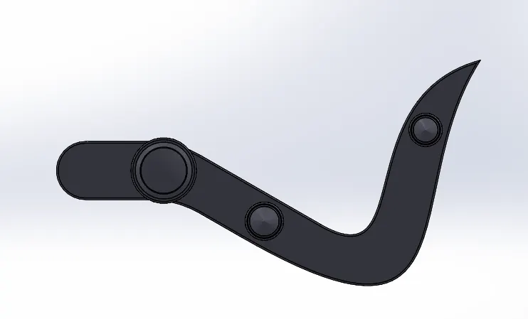
Isometric view
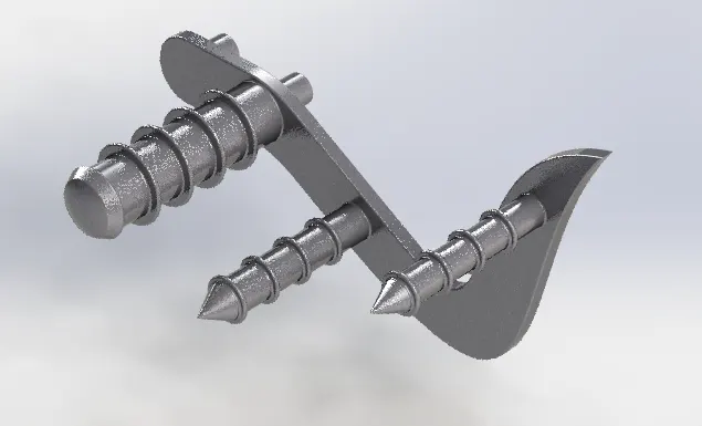
Tools & Features used:
Sketch: To create required sketches
Line: To drawing lines and construction lines
Circle: To draw circle
Arc: To draw arc
Spline: To draw curves through interpolation of points
Boss-Extrude: To obtain 3d solid from 2d sketch
Boss-Revolve: To revolve 2d sketch along the reference to obtain solid body
Combine: To combine or merge solid bodies
Dome: To create dome surfaces on flat surfaces
Fillet: To convert sharp internal or external edges into smooth or round edges
Chamfer: To convert sharp edges into bevel edges
Linear Pattern: To create a pattern of feature or body along a linear reference
Smart dimensions: To add or edit dimensions of sketches
Transmission belt:
Front view
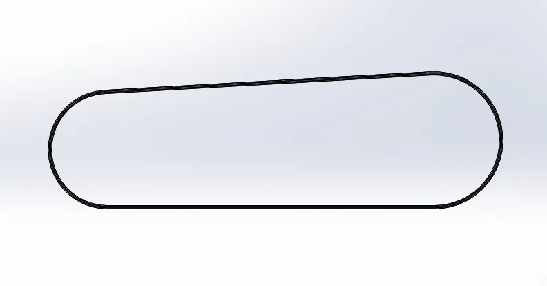
Side view
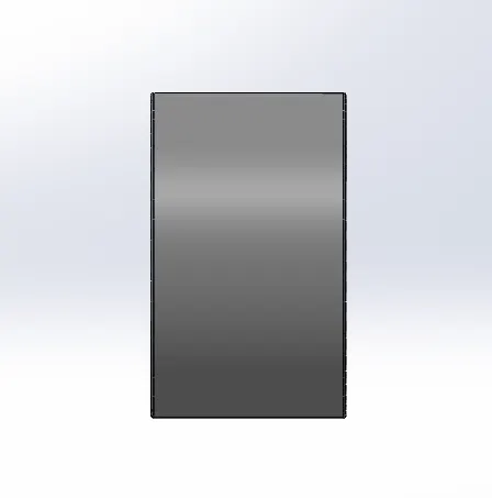
Isometric view
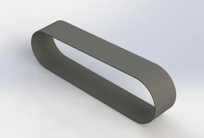
Tools & Features used:
Sketch: To create required sketches
Line: To drawing lines and construction lines
Arc: To draw arc
Boss-Extrude: To obtain 3d solid from 2d sketch
Fillet: To convert sharp internal or external edges into smooth or round edges
Smart dimensions: To add or edit dimensions of sketches
Kick stand:
Front view
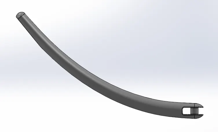
Side view
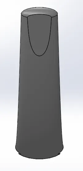
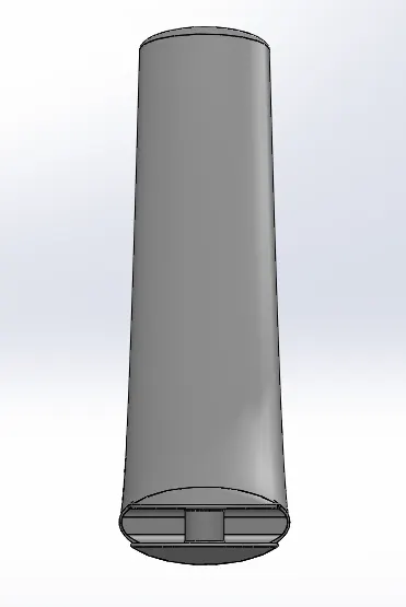
Isometric view
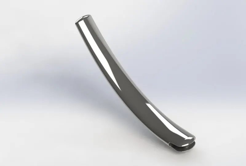
Tools & Features used:
Sketch: To create required sketches
Line: To drawing lines and construction lines
Arc: To draw arc
Boss-Extrude: To obtain 3d solid from 2d sketch
Dome: To create dome surfaces on flat surfaces
Cut-Extrude: To subtract a solid portion from a solid using 2d sketch
Loft: To create surface along the profiles
Split: To separate or split solid bodies
Fillet: To convert sharp internal or external edges into smooth or round edges
Smart dimensions: To add or edit dimensions of sketches
- Upload a min of five screenshots of the Assembly Model in the report. (For eg:-Front View, Side View, Isometric View, Camera Setup View, and the Top View) -
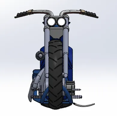
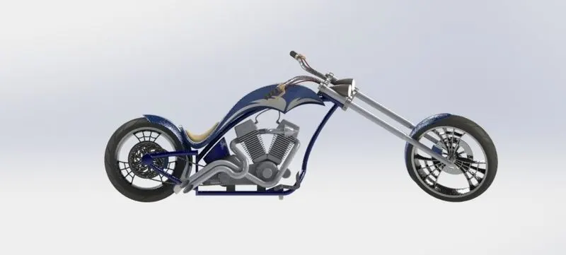
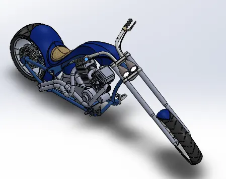
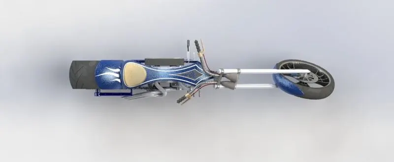
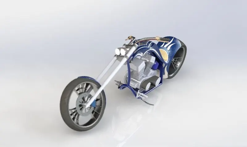
- Attach Detailed Rendering Images of Assembly -
- Conclusion -
- All the parts of the chopper are modelled and assembled together successfully using Solidworks.
- The assembled chopper is rendered using Photoview 360 and Solidworks Visualize.