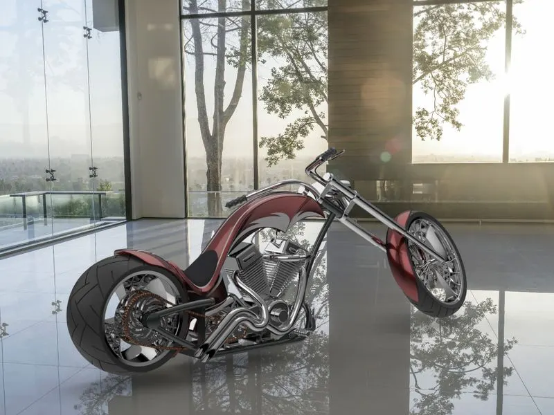
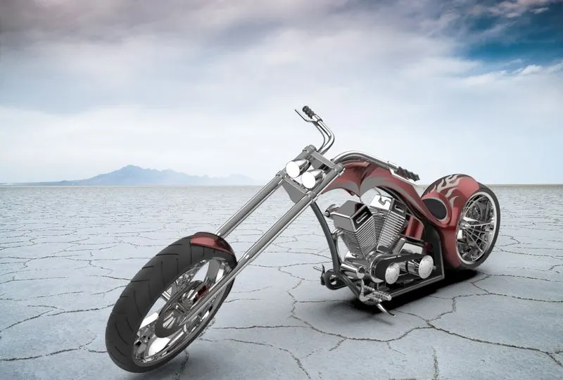
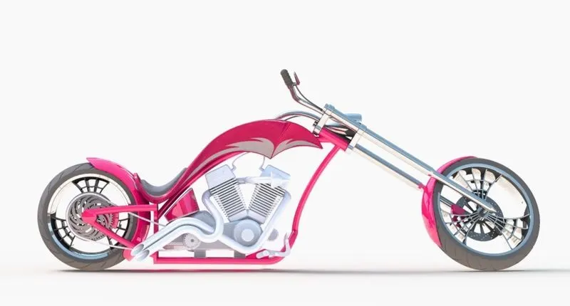
Photo Realistic Rendering
1.REPORT ON ASSEMBLY OF CHOPPER MODEL
DESIGN OF AMERICAN CHOPPER USING SOLIDWORKS
OBJECTIVE
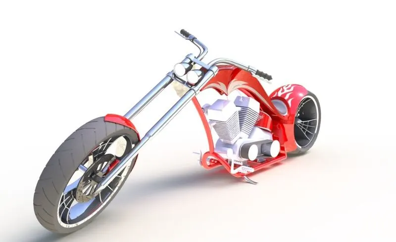
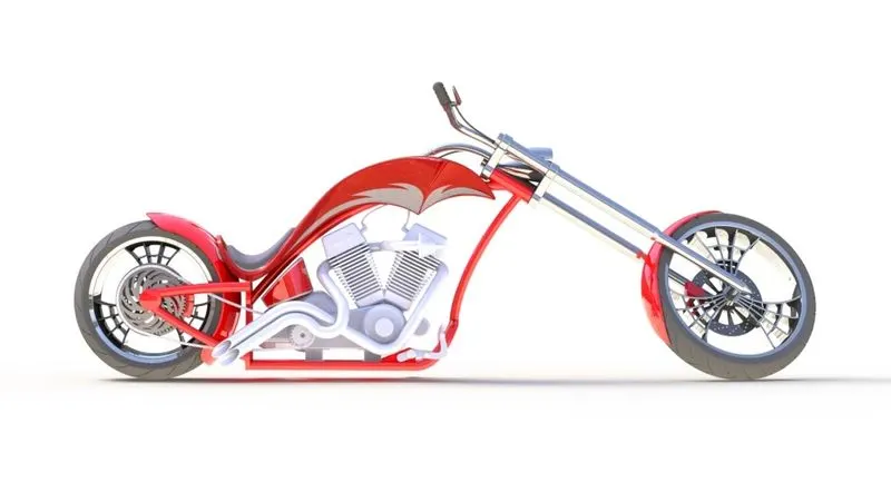
The objective of the project is to model an AMERICAN CHOPPER using SOLIDWORKS and to render it with SOLIDWORKS visualize to create a photorealistic view of it.
INTRODUCTION
This project explains the designing of American chopper using the CAD software SOLIDWORKS from sketching the parts and modelling them to final rendering of the assembly to give a photo realistic view.
METHODOLOGY
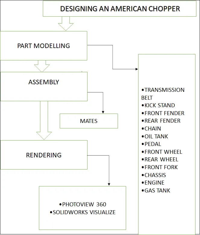
- Part Modelling
- Assembly
- Rendering
FLOW CHART
DESCRIPTION:
There are number of parts designed to get the final shape of american chopper and are enlisted below:
1) TRANSMISSION BELT
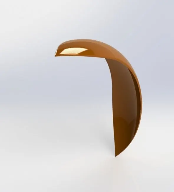
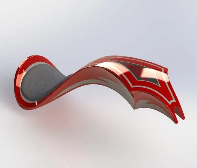
2)FRONT FENDER
Following features/tools are used for designing front fender:
- Revolve
- split
- fillet
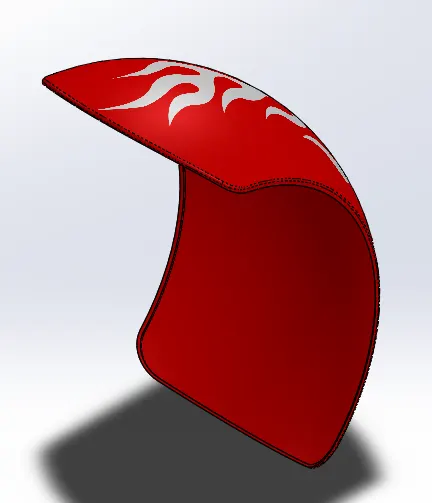
3) REAR FENDER
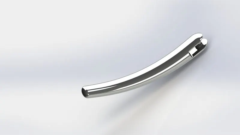
4) KICK STAND : It is used to provide the support to the chopper to stay on rest when not in use.
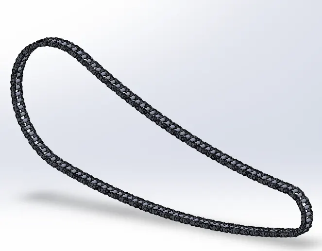
5) CHAIN: It is a connecting link which is used to transmit power from one shaft to other shaft with the help of sprockets. It is made up of various small links.
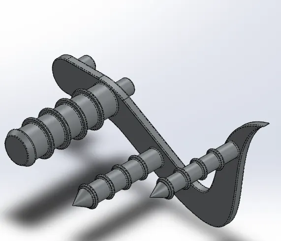
6) PEDAL: Pedal is the part used as the foot rest for the rider. Also, gear shifting mechanism is attached with the pedal majority times.
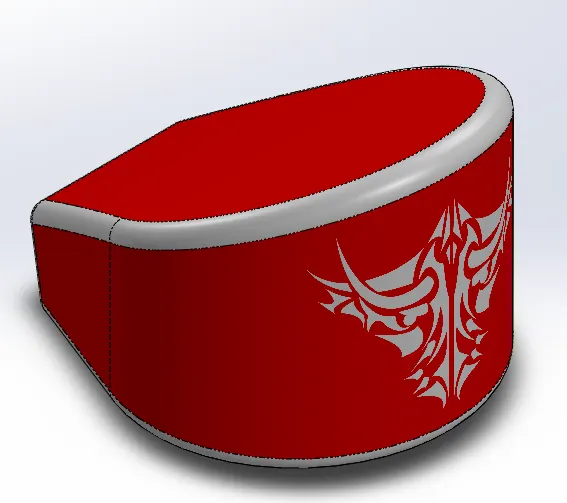
7) OIL TANK: It is used for storing lubricating oil which flows over the moving parts , reducing friction and heat generation.
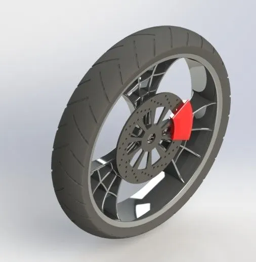
8) FRONT WHEEL
9) Rear Wheel
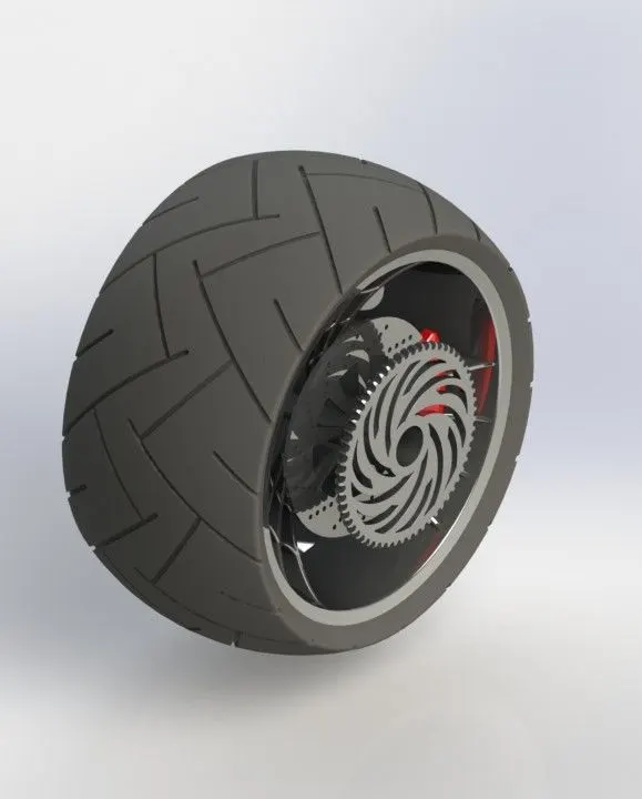
10)CHASIS
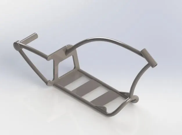
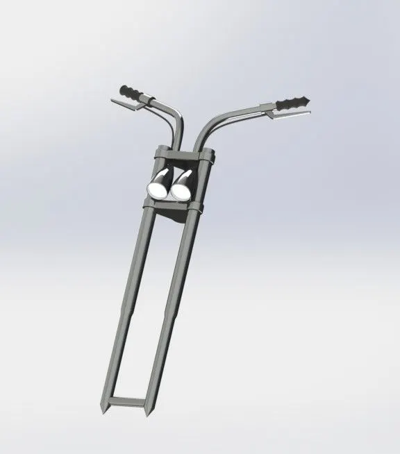
11) FRONT FORK
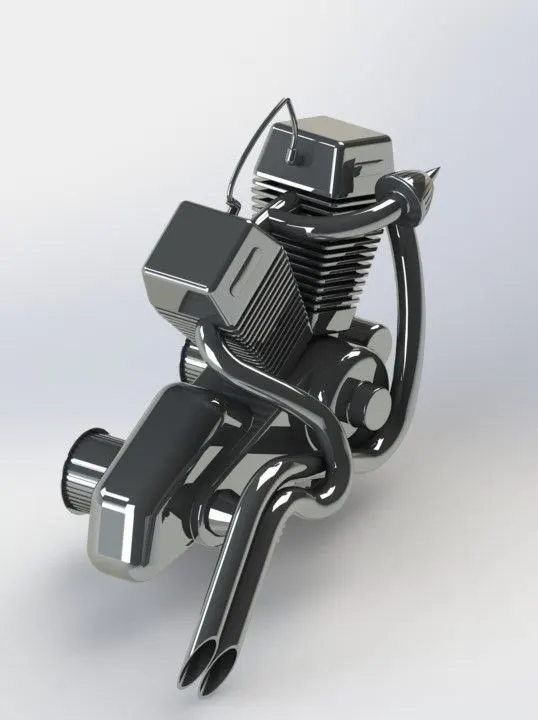
12) ENGINE:
13) GAS TANK
The major tools or features that were used in the designing of the American chopper are as follows:
1)2D-Sketch: It is basically a 2d drawing of the model which is drawn as per the dimensions and later converted into the 3d part file.
2) Geometric Relations: These are the relations that are typically used while 2d drawing and act as a most powerful feature for defining the sketch.
3)Extrude: This is a feature which help us to extrude a sketch or a selected sketch contours in one or two directions.
4) Extrude Cut: This feature help us to remove or cut the material from the 3d model. It is used for creating channels, holes or slots,etc.
5)Revolve Boss: This feature is used where we need a cylindrical 3d part and it can be created with the help of the axis.
6)Revolve Cut: It cuts a model by revolving a solid profile around a axis.
7)Swept Boss: With the help of a line or a spline, the feature is used to sweep a closed profile along an open or closed path to create a solid feature.
8) Loft: It helps in creating a shape by making transition between multiple profiles and guide curves thus allowing to create complex geometery with a single tool.
9)Dome: A dome is a rounded vault forming the outside face of the body or structure, typically with a circular base.
10) Curve Driven: This pattern tool allow us to create a pattern along a planar or 3d curve.
11) Fillet: Help us to create rounded external or internal face of the part like edges or edge of a face.
12) Chamfer: This command is used to connect two adjacent faces using an inclined plane.
13) Split: This feature help us to create multiple parts from an existing part such that we can create a new part file and use it into assembly modeling.
14) Combine: In a multibody part, it help us to combine multiple bodies to create a single body.
15) Projected Curve: It help us to create a 3d curve on a model. Also, we can create a 3d curve that represents the intersection of two extruded surfaces generated by creating sketches on two intersecting planes.
16)Shell: This tool is used for creating a hollow part from a solid 3d body by adjusting its thicknes value.
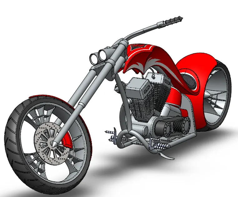
ASSEMBLY MODEL:
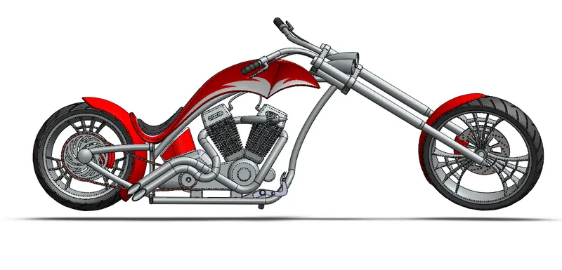
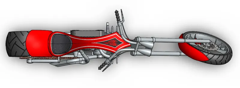
TOP VIEW
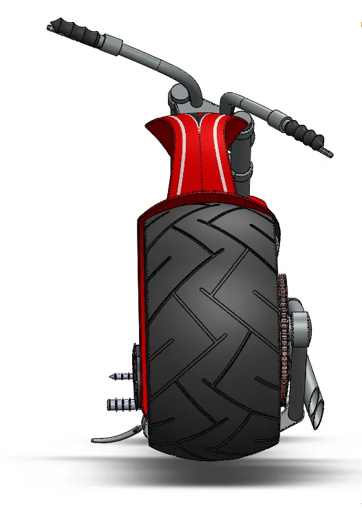
BACK VIEW
FRONT VIEW
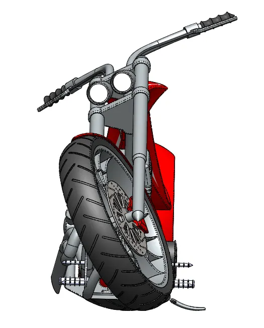
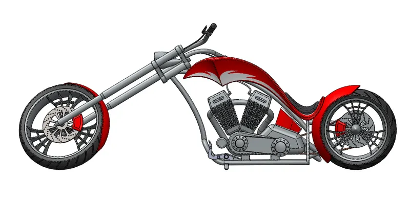
CAMERA VIEW
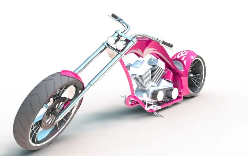
RENDERED IMAGES OF AMERICAN CHOPPER:
CONCLUSION: In the American Chopper 3d modelling project, I learnt about various 3d modelling tools, assembling modelling as well as techniques of photo rendering.