Photo Realistic Rendering
Project: American Chopper (Designing & Rendering)
Objective:
Objective of this project is to design the components of American chopper, create an assembly, add decals and to render images as an output using solidworks and Solidworks visualize softwares.
Introduction:
A chopper is a type of custom motorcycle which emerged in the US state of California in the late 1950s. A chopper employs radically modified steering angles and lengthened forks for a stretched-out appearance. This report contains the detailed explanation of design, assembly and rendering of an American chopper.
Flow of chart:
| Designing the components of Chopper |
`downarrow`
|
Assembly of Chopper |
`downarrow`
|
Apply decals & environment setup |
`downarrow`
|
Rendering |
Design:
Designing of Chopper involves designing the components of Chopper. The following parts are modelled and assembled using solidworks.
- Chassis
- Engine
- Pedal
- Kickstand
- Transmission belt
- Oil tank
- Chain
- Gas tank
- Front end fork
- Rear wheel
- Rear fender
- Front wheel
- front fender
Chassis:
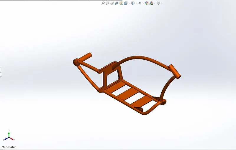
Chassis, also known as 'Frame', is the foundation structure of any vehicle that supports it from underneath. The purpose of the chassis is to bear the weight of the vehicle in its idle and dynamic states. While designing the chassis in solidworks, first we have to create a stable base and a tublar frame to make an engine to be mounted on to that.Used Curves feature to create a layout/profile of the tublar frame. Since we are dealing with 3D profile, we have sketch the profile on a 2D planes and we need to use curves feature to combine them to make a 3D profile. Sweep feature is used to make the tube profile. To make a base where engine get mounted on can be made using Extrude feature. Extrude feature is used to create back plate and bottom plate and Sweep profile is used to make the frame connecting to the back wheel. Finally, Holes for mounting pedals are made on the side plate on the frame using hole feature. Sweep featire used again to create a tublar profile for front fork and rear wheel attachement.
Images of the chassis are attached below.
Engine:
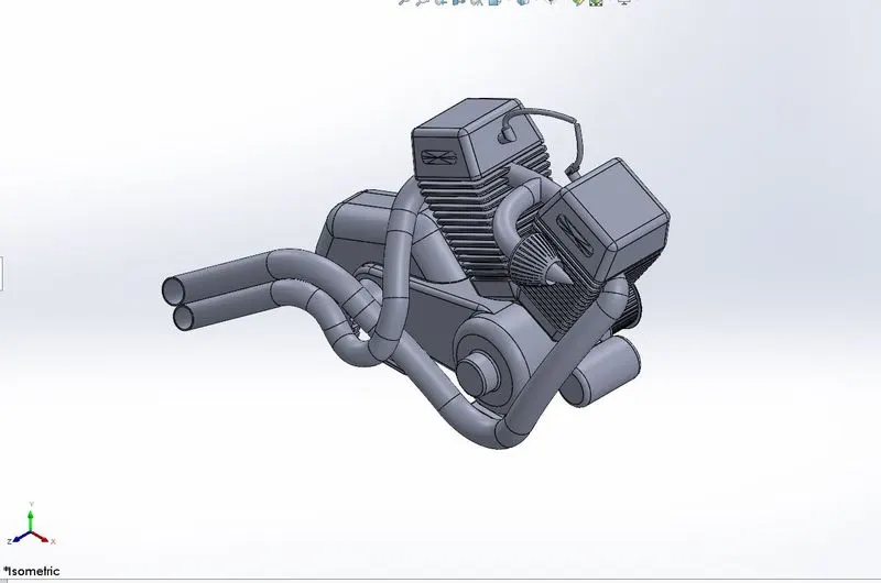
Engine is the most complex part to design in Chopper assembly.Engine is mounted on the chassis frame designed earlier. The engine design involves features like Boss Extrude, Extrude cut for design the gear box below the cylinders assembly, then we indulge in designing the belt drive using Exturude and Circular patern for the toothed gears. The Cylinder blocks are made on the top of the gear box using extrude feature and Exturude cut is used to create the Fin feature on the cylinder block. Linear pattern in used to create multiple fins feature on the Cylinder block and finally mirror feature is used to create a twin cylinder block. Finally, curves feature are used to make 2 drawings into 3D line profile to create the exhaust pipe. same feature is used to create the wiring for the spark plug.Pinion is designed on the engine using the extrude and the gear contours are created using the extrude cut feature, then tooth profile is patterned using circular pattern to obtain the pinion design.
Images of the engine attached for ref.
Pedal:
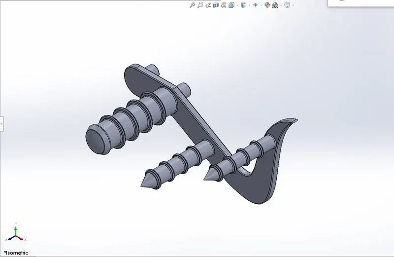
Pedal is formed using the simple Boss extrude and revolve feature. linear pattern is used on the foot rest area to create a realistic look. Dome feature is used to create a half sperical look on the revolved feature and finally some boss extrude is made for mounting the pedal to the chassis. Fillets are added at the required places.Once RHS pedal is created We use mirror part feature to create the LHS and it can be mounted on the respective side of the chassis.
Images of pedal is attached below.
Kickstand:
Kickstand is the part which bears whole weight of the chopper at parked condition. It uses simple loft and Extrude and Cut features to create the stand.Dome feature is used to create a roundness look. Split is used to create a flat surface parallel to the land surfcae when parked
Image of Kickstand attached for ref.
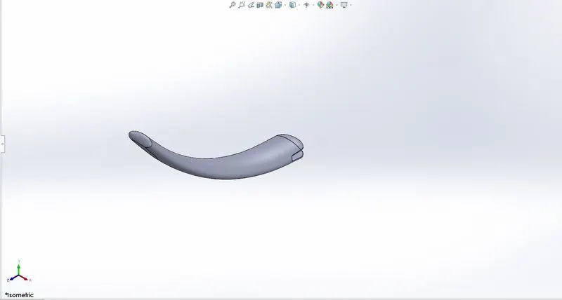
Transmission belt:
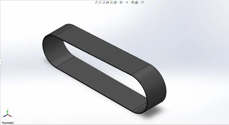
Transmission belt uses Extrude and Fillet feature to create it. Profile of the beslt is sketched and extrude feature is used on it. Simplest feature used to create the belt.
Image of transmission belt attched for ref.
Oil tank:
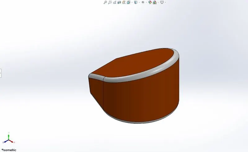
Oil tank has some non standard contours and that can be achieved using the combine feature. First create two different extrudes which will justify the shape of the oil tank and use combine feature which will delete the unjoined surfaces such that creates the non standard shape easily. then used fillet and Shell feature to make hollow space inside to hold the oil.
Image of the oil tank is attached for ref.
Chain:
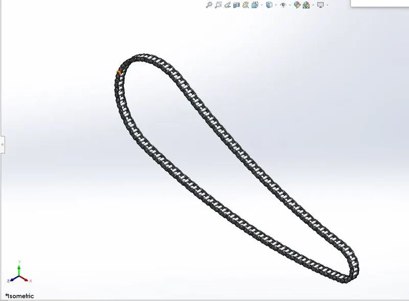
Chain uses simple features to create them. The profile of the chain is drawn first and we trace the profile to create the whole chain assembly. Create the outer plate and Pins using extrude feature and and then create the subsequent inner plate using extrude feature. Apply fillet on required places and use curve pattern until the intersection of the curve and circular profile. Similary we have to do the same until the complete loop is formed and finally we can create the mirror of the one sided outer and inner plates.
Image of the chain is attached for ref.
Gas Tank:
In chopper design, the gas tank and passenger seat is intergrated. Most of the feature used in gas tank design are surface modelling features like curves and loft and surface trim and surfcae knit features. used surface sweep feature to create the profile of the gas tank and knit feature is used to structure the shape of the gas tank. Then the surface lofted on one side is mirrored using mirror feature and then surface loft to used to created a enclosed contour. Shell command is used to create the hollow feature. the seat area is created using split line and is surface extruded to create a embossed surface. Image of the gas tank is attched for ref.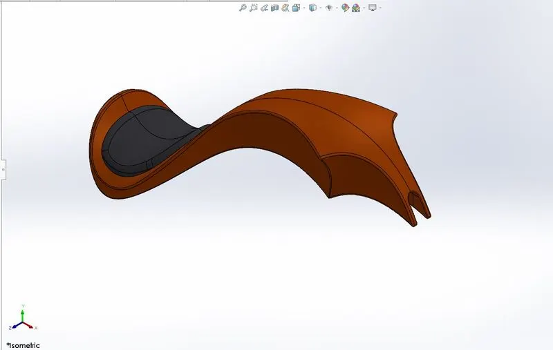
Front end fork:
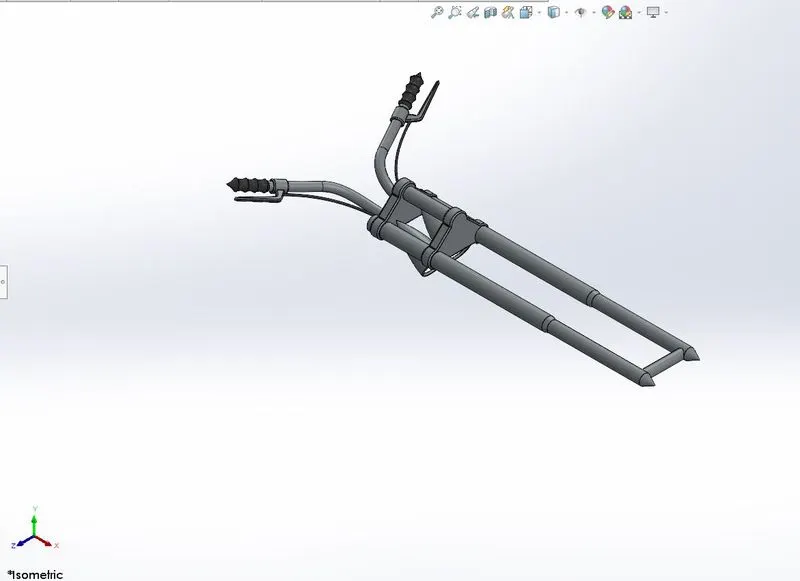
Front end fork is the link assembly which help as to control the chopper in terms of turning, acceleration and brakes. Front fork is attached to the chassis frame and connected to the front wheel. Chopper design involves long front fork end and this is achieved using features like Boss Extrude , revolve and linear pattern. Revolve is used to make the headlight of the chopper. Sweep feature is used to create the electrical wires and revolve is used for creating the handle bar etc. Image of the front end fork is attached for ref. Front end fork is a multi body part and respective materials color are applied on the part for visual representation.
Rear Wheel and front wheel:
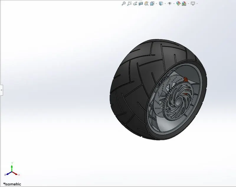
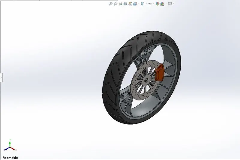
Both wheels are multibody parts which contains different materials like tyre(rubber), Sproket(Metal), rim(metal) and calipers. Most commonly used feature for wheel are revolve, Boss-extrude, Cut extrude, cir pattern for disc plate design and sprocket design and hub design involves revolve feature. The tyre(Rubber material) is created using revolve feature and painted black for representation. Extrude cut option is used to produce the threads on the tyres.Image of the wheels are attached for ref.
Front fender and Rear fender:
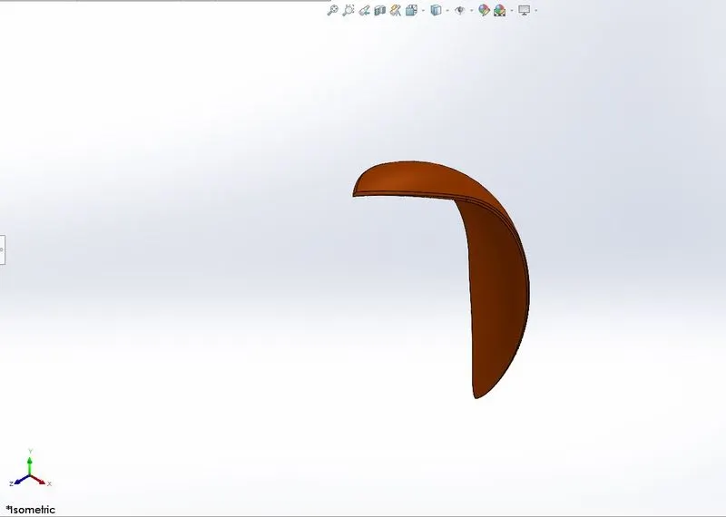
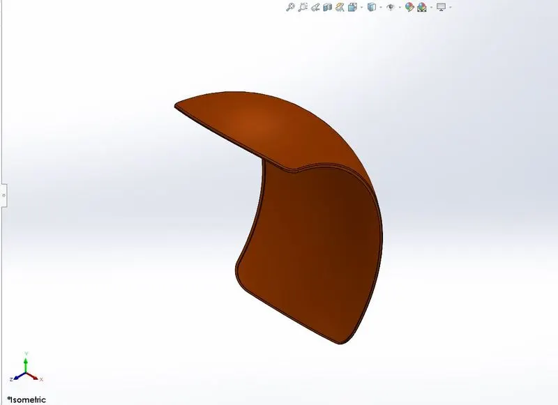
Fender design involves simple revolve ans shell feature to create the contour. split feature is used to define the ends of the fender.Image of the fender is attached for ref.
The chopper is assembled using mates and points.
Applying decals and environment settings:
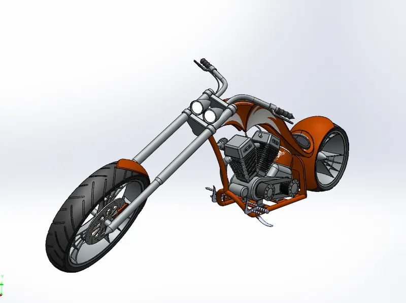
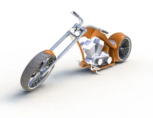
Decals are kind of stickers or lables applied over the surface of the parts to make the chopper look more realistic. Decals are applied in the appearance section and aligned properly to create the asthetic look. the Environment is setup using Photo360 and solidworks Visualize software.Images of photo360 renders and camera view setup are attached for ref.
Rendering:
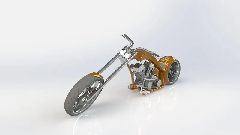
Rendering is done using the solidworks Visualize software. High quality images can be rendered using Visualize tool and make them mmore realistic. proper camera and light settings are aligned in order to create the efficient lighting and realistic look as natural.
Images of rendered images are attached for ref.
Conclusion:
Thus american chopper has been designed, assembled, added decals and environment setup has been setup for rendering and the final render images have been attached for ref.