Photo Realistic Rendering
MODELLING and PHOTO-REALISTIC RENDERING of an AMERICAN CHOPPER
OBJECTIVE:
To learn how to create a Model of an American Chopper and make its Photo Realistic Rendered Image using Solidworks Software.
INTRODUCTION:
An American Chopper is a type of custom motorcycle which emerged in the US state of California in the late 1950s. A chopper employs radically modified steering angles and lengthened forks for a stretched-out appearance. They can be built from an original motorcycle which is modified ("chopped") or built from scratch.
This project report gives details about how the American Chopper Model is designed by part modelling and assembling in Solidworks and how to render the model to get a photo-realistic view/image using the Solidworks Visualise tool.
This report is fragmented into weekly challenges, it consists of 8 weeks of work and the result of which is also shown sequentially. The tools and features used in the making of parts, assembly and render are also explained.
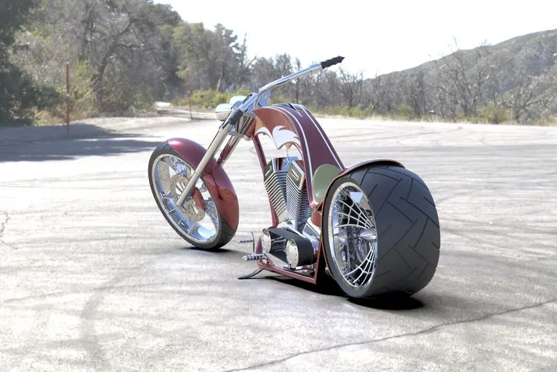
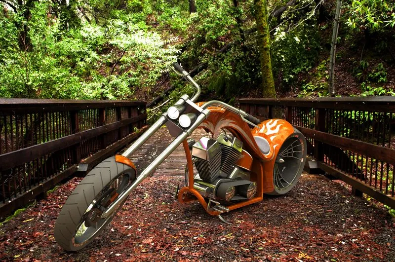
One of the Photo-Realistic Image of the American Chopper model that is rendered in this project is shown below:-
DESIGN METHODOLOGY:
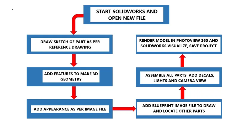
STEPS FOR DESIGN:
MODELLING:
THE AMERICAN CHOPPER CONSIST OF THE FOLLOWING PARTS
- Transmission belt
- Kickstand
- Front fender
- Rear fender
- Chain
- Oil tank
- Pedal
- Front wheel
- Rear wheel
- Rear fender
- Front fork
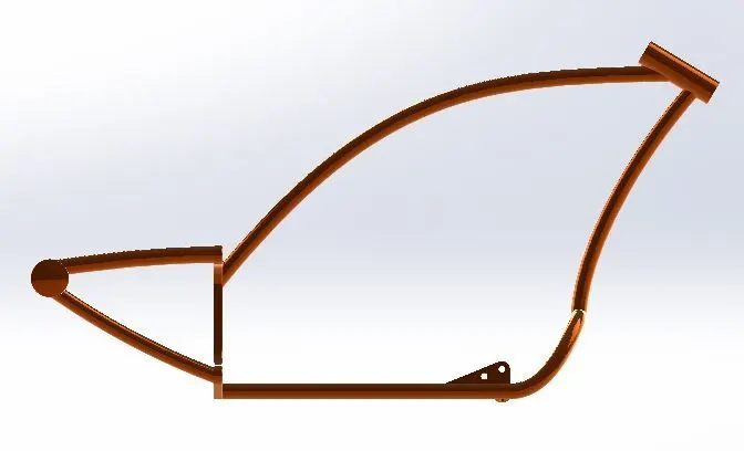
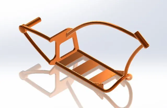
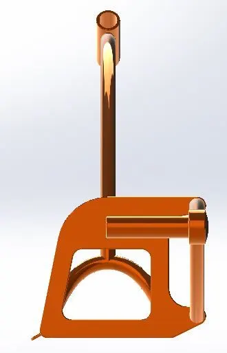
- Chassis
- Engine
All the above parts are designed separately and sequentially and finally assembled together to get the model of the American Chopper.
Features Used
SKETCH:
- Sketch feature is used to draw the 2-Dimensional view of the design on a plane out of the 3-planes which are Front, Top and Side planes. It contains tools to draw different types of lines, curves and shapes which are called Sketch Entities, like arcs, straight lines, circles, splines etc.
OFFSET:
- Offset is used to draw or copy a sketch entity parallelly inwards or outwards at a given distance.
EXTRUDE BOSS/BASE:
- This feature is used to extend the surface (inside closed sketch/fully defined sketch boundaries) to its third dimension and make a 3-dimension figure.
LOFTED BOSS/BASE:
- This feature is used to produce complex type of geometries; by interpolating surfaces between different cross-sections of a model, known as loft profiles.
FILLET:
-
It is used to round the edges or faces of geometry internally or externally.
CHAMFER:
- It is used to cut the edges or faces symmetrically or assymmetrically.
SPLIT:
- It is used to created multiple bodies from a single geometry.
DOME:
-
It is used to create a curved solid over a planar face.
EXTRUDE CUT:
- Extrude cut is just same as Extrude boss feature working boundaries, but here instead of making solid it wipes out the solid coming in its way up to value given to it.
REVOLVE:
-
Revolve feature creates solid around the center line at a distance given from the center line
DYNAMIC MIRROR:
- It is used to mirror the pre-selected sketch entities.
COMBINE:
-
The combine feature is used to add two or more solid geometries into a single solid.
TRIM ENTITIES:
-
It is used to cut the sketch entities and also can extrapolate them using its tool i.e. power trim.
SHELL:
-
It makes the solid geometry hollow of thickness given to it.
LINEAR PATTERN:
-
It is used to create instances at the linear fashion of 2-D or 3-D figures. The particular instances can be skipped according to requirement.
CIRCULAR PATTERN:
-
It makes circular pattern of entity and can adjust the rotaion of entity also.
SURFACE MODELING:
- Surface modelling is used where complex curved surfaces need to be designed like in making the Gas tank and seat of a motorcycle.
Project Curve:
Sweep:
LOFTED SURFACE:
-
Loft surfaces are surfaces developed by several 3D curves or existing edges that create a smooth tangency between the curves chosen.
SWEPT SURFACES:
-
Sweep Surfaces are the surfaces which are created along a given path from a segment curve.
FILLED SURFACE:
-
A surface patch with any number of sides is built by the Filled Surface function, inside a boundary defined by existing model edges, sketches, or curves, including composite curves.
SURFACE TRIM:
-
It is used to cut away material from a board and it offers two modes which are Normal and Shared.
EXTEND SURFACE:
-
Extend surface is used to extend the surface tht is already made.
Surface Knit:
-
The two free edges / open edges of the surfaces are knit together by Surface Knit. It also eliminates the distance between the two surface edges.
Mates:
- Mates feature is used to assemble the two parts and defining the various relations between them like distance, rotation or other limitations.
APPEARANCES:
-
When a part is designed, it needs to appear like what it is designed for. So, colours, textures, and reflectivity is given to it according to its desired appearance and its material.
The project is done in 8 weeks to make 13 parts, their assembling and the assembly rendering. In each week different parts are designed which are shown below weekly wise.
Week 1: 1. Transmission belt, 2. Kickstand, 3. Front fender, 4. Rear fender
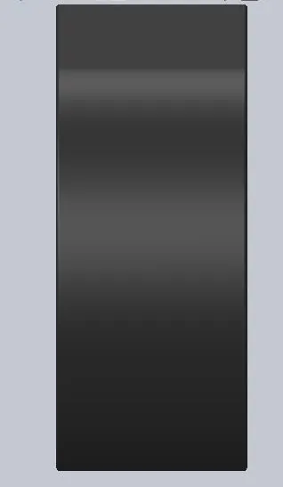
1. Transmission Belt:
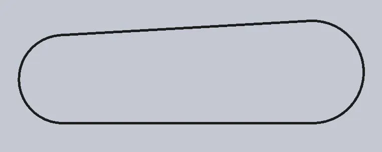
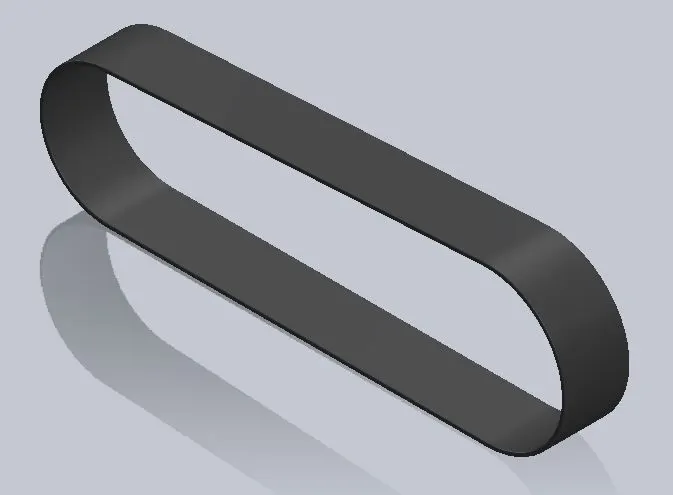
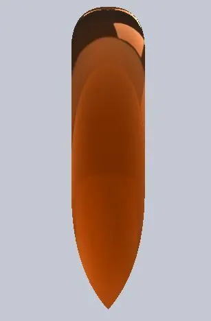
The transmission belt is to transfer power from shaft connected to output of engine to the input of gearbox. The sketch of belt is made by connecting small circle and large circle using tangency and extra circular part is trimmed using power trim. 3.5 mm thickness is given using offset tool. It is then extrudedand given matte rubber appearance.
FEATURES USED:
- Boss Extrude
- Fillet
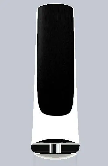
2. Kick stand:
Kick stand is a supportive framework provided to a bicycle or motorcycle to help it stand while stationary in a vertical position.
FEATURES USED:
- Sketch
- Loft
- Dome
- Extrude Boss
- Extrude cut
- Fillet
- Split
- Appearances
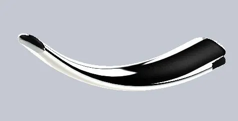
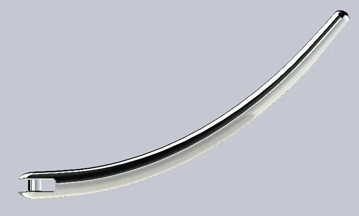
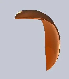
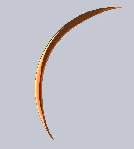
3. FRONT FENDER:
- Sketch
- Offset Entities
- Trim entities
- Revolve
- Dynamic mirror
- Split
- Appearances
- Sketch
- Offset Entities
- Trim entities
- Revolve
- Appearances
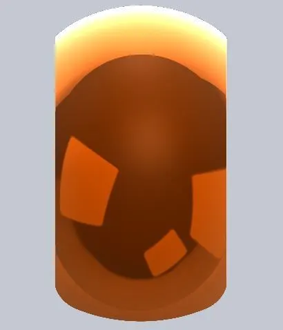
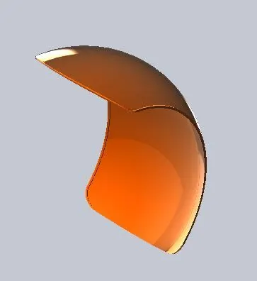
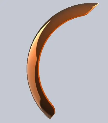
Week 2: 5.Chain 6.Oil tank 7.Pedal
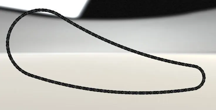
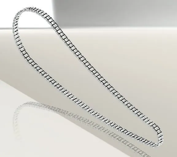
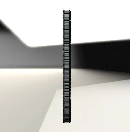
5.CHAIN
Chain is the kinematic mechanism that is used to transmit power from the engine to the rear wheel. It passes over toothed members that are known as sprockets.
FEATURES USED:
- Sketch
- Trim
- Fillet
- Blocks
- Extrude
- Mirror
- Patterns
- Appearances
6. OIL TANK
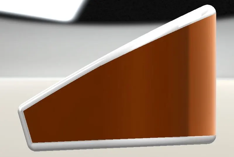
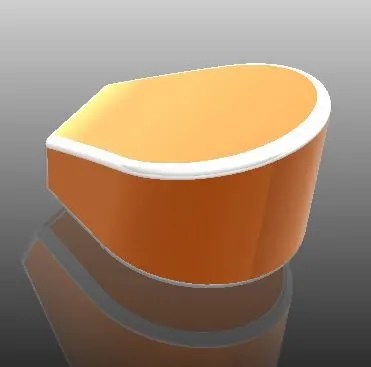
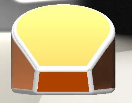
- Sketch
- Boss Extrude
- Combine
- Fillet
- Shell
- Appearances
7. PEDAL
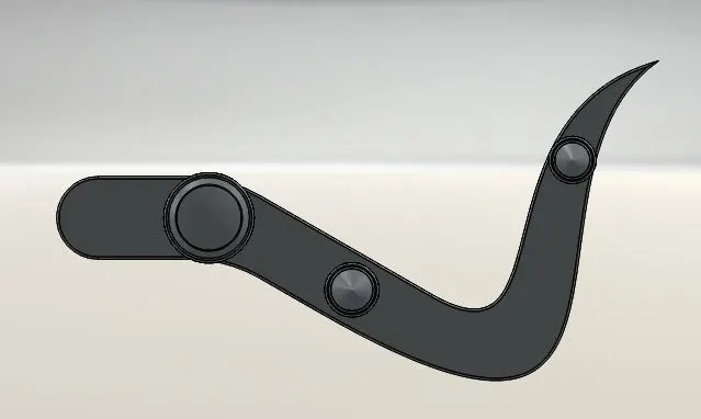
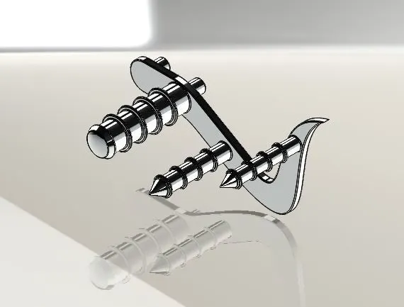
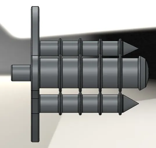
The pedal in the motorcycle here is mounted on the footrest to switch gears or to apply rear brakes of the motorcycle.
FEATURES USED:
- Sketch
- Extrude
- Fillet
- Linear pattern
- Dome
- Chamfer
- Appearances
Week 3: 8. Front wheel
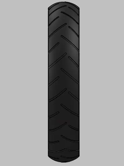
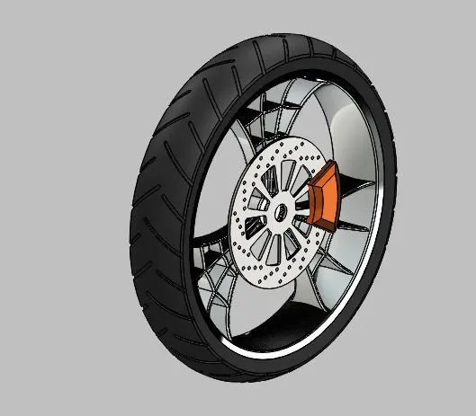
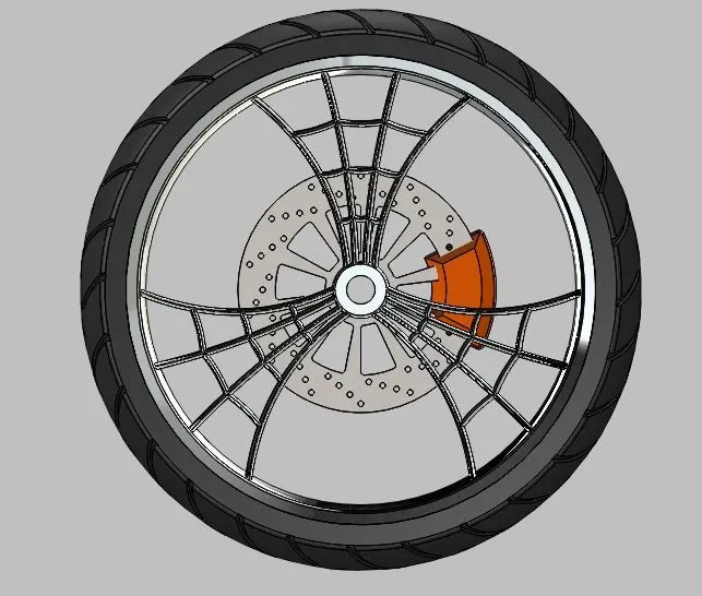
8. FRONT WHEEL
FEATURES USED:
- Extruded Boss
- Cut Extrude
- Revolved Cut
- Circular Pattern
- Combine
- Fillet
- Chamfer
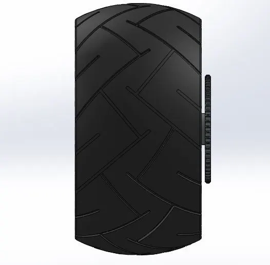
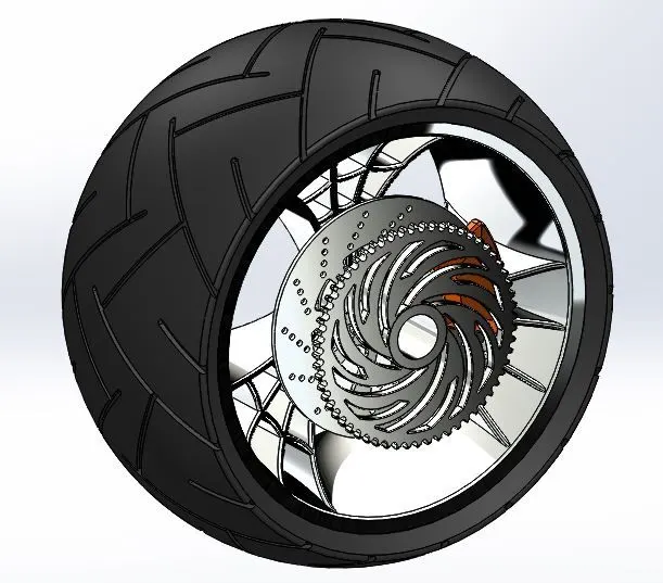
FEATURES USED:
- Sketch
- Revolve
- Trim
- Fillet Entities
- Boss/Base Extrude
- Planes
- Revolve Cut
- Linear pattern
- Chamfer
- Fillet Features
- Cut Extrude
- Circular Pattern
- Appearances
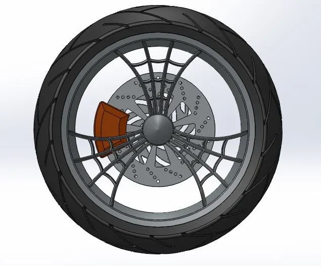
10. FRONT FORK
FEATURES USED:
- Extruded Boss
- Revolved Boss
- Fillet
- Extruded Cut
- Dome
- Revolved Cut
- Swept Boss
- Project Curve
- Mirror
- Combine
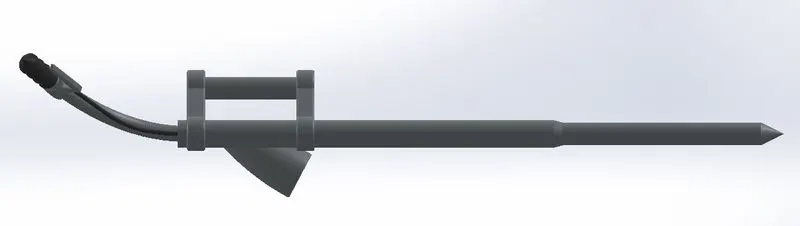
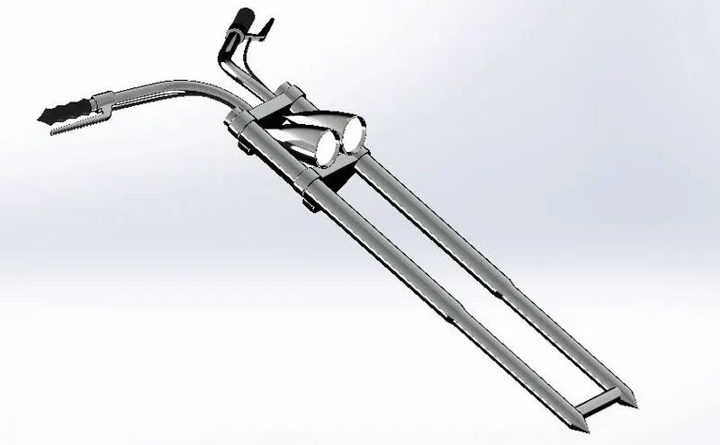
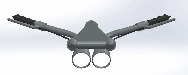
- Sketch
- Offset
- Convert entities
- Project Curve
- Trim
- Plane
- Sweep
- Split
- Revolve
- Cut Extrude
- Fillet
- Combine
- Appearance
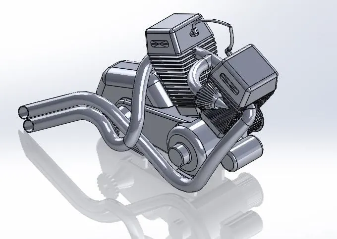
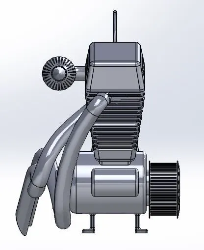
12. ENGINE
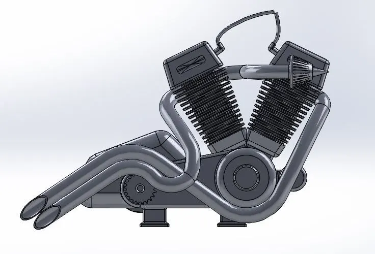
An engine is a device that is used to transform the chemical energy of the fuel into mechanical energy.
FEATURES USED:
- Sketch
- Convert entities
- Trim
- Revolve
- Boss extrude
- Cut extrude
- Offset
- Dome
- Fillet
- Project curve
- Composite curve
- Sweep
- Mirror
- Circular Pattern
- Split
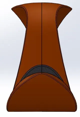
Week 6: 13. Gas Tank
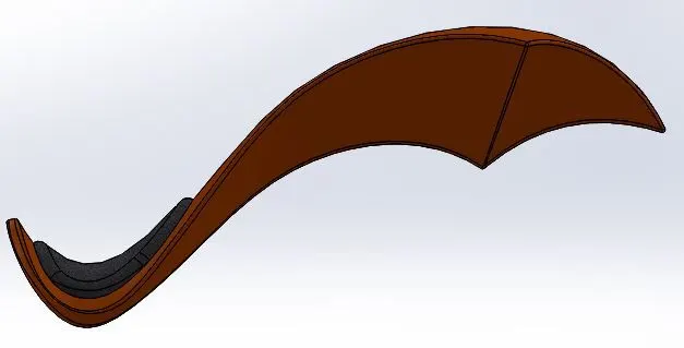
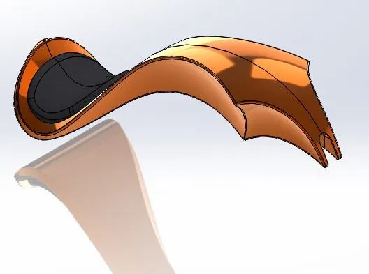
13. GAS TANK
It is a safe reservoir of the fuel that is used to fire the engine.
FEATURES USED:
- Sketch
- Trim
- Project curve
- Convert entities
- Sweep Surface
- Loft Surface
- Fill surface
- Surface trim
- Surface knit
- Sweep cut
- Fillet
- Appearance
Week 7: Assembly
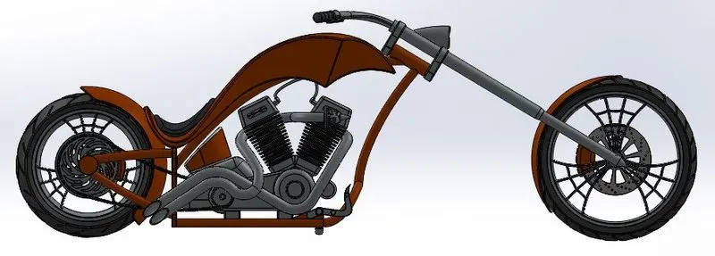
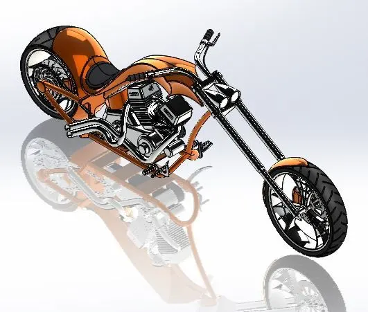
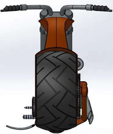
Assembly of the American Chopper
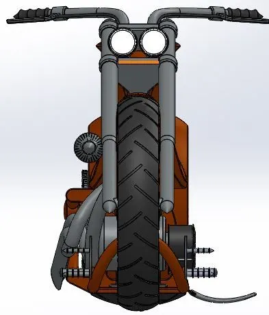
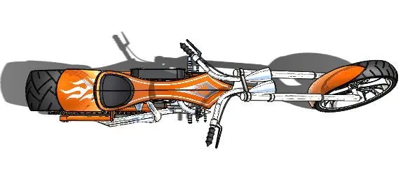
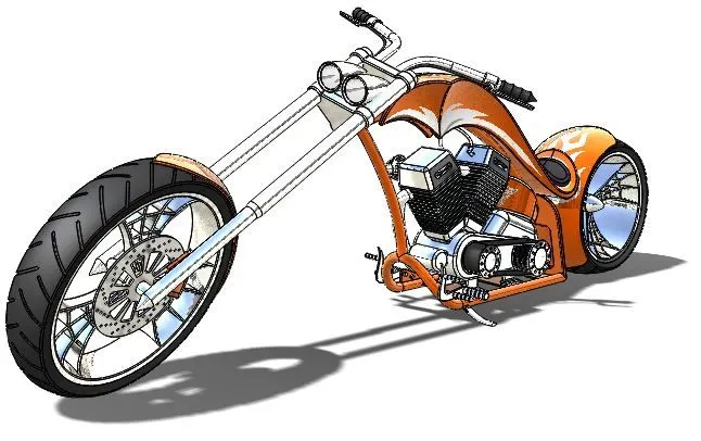
- In Solid Works, all the designed parts are taken into the assembly section and mated as per the design. After that the decal are added to the various parts.
- Various mating relations are used here like Coincident, Concentric, Tangents, and Distance when making Assembly.
- Mates
- Insert part
-
Rendering is the method of making the reality-based accurate appearance and presentation of the Photorealistic model.
- Camera view is used to get a better perspective of the model.
- Lights are also added to get better lighting and reflections of the model.
-
In SolidWorks, rendering has been accomplished in two respects. The two manners are as follows;
-
Photoview 360
-
Visualize Solidworks
-
Any of the mate conditions and locations are altered in the photorealistic model to make realistic ones. Then, from various perspectives, the photorealistic model is turned into functional pictures.
1.Photoview 360 Render
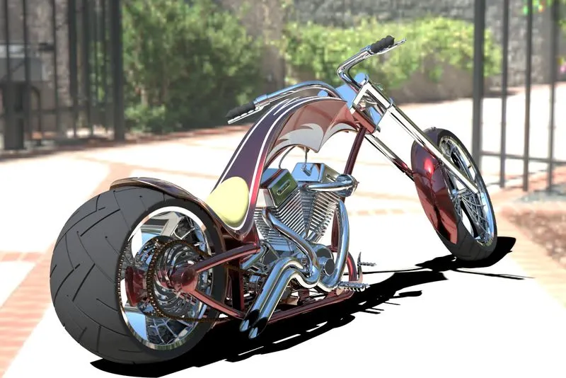
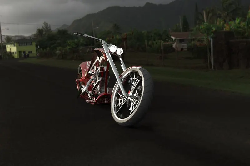
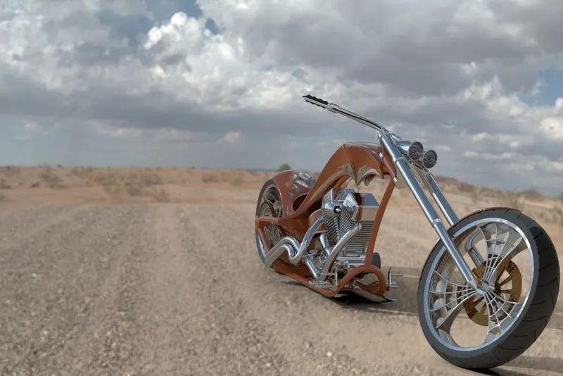
2.Solidworks Visualize Renders
Conclusion :
-
The components of the chopper are sketched and modelled in SolidWorks.
-
The components are placed into the setting of the assembly and assembled by applying the mates on the American Chopper.
-
Using 'Photoview 360 & SolidWorks Visualize, the realistic image is rendered.