Photo Realistic Rendering
Objectives:
1. To get introduced to the Solidworks user interface.
2. To fully define the 2D sketches and conversion to 3D of the same.
3. To understand the sketching features such as projected curves, offset entities, etc,
4. To understand the surface modeling and assembly of the various components of the American chopper.
5. Rendering of models in Solidworks using Photoview 360 under Render tools.
Different Components of the American Chopper:
1. Transmission Belt
2. Kickstand
3. Front and Rear Fender
4. Chain
5. Oil Tank
6. Engine
7. Front Fork
8. Front and Rear wheel
9. Gas tank
10. Chassis
11. Pedal
Modeling of the components:
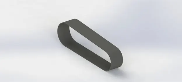
1. Transmission Belt
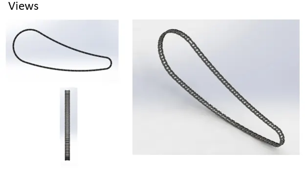
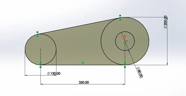
Extruded the above sketch for a distance of 88mm to get the belt.
Matte Rubber was assigned as material for the belt.
Kick Stand
Sketch
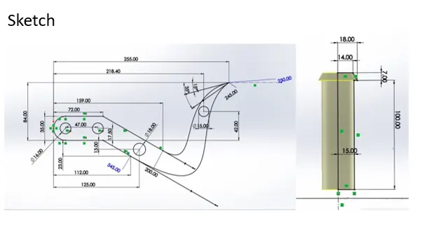
The loft command is used for which the two profiles are the two ellipse at the end of the spline. The spline acts as a guiding curve for the profile
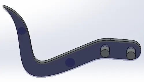
3D model
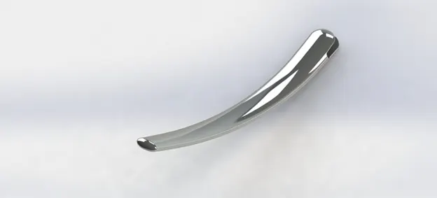
Additional cut for the kickstand was given at the pivoting point where it is attached to the chassis of the chopper
Front Fender
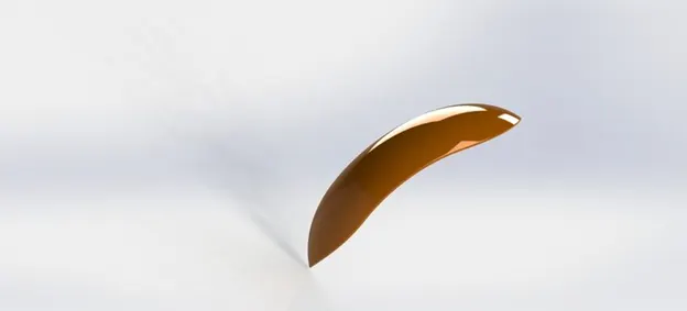
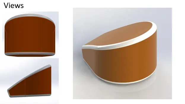
Revolve command is used in which 5 degrees for direction 1 and 130 degrees was used for direction 2.
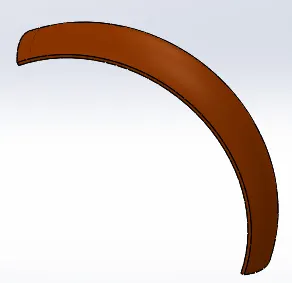
Cut out at one end of the fender:
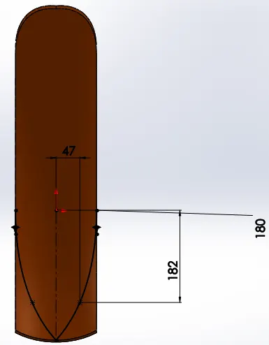
A similar Cutout is done at the other end of the fender.
Rear Fender:
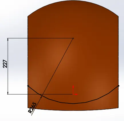
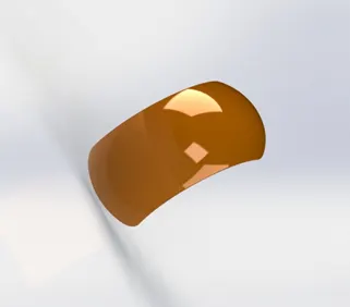
The design of the rear fender is similar to the front fender except for the dimensions as the rear wheel is wider than the front wheel hence the rear fender is wider than the front fender.
Cut out at one end of the rear fender.
Chain
Chain profile
Chain Links
Modeling the entire outline sketch and negotiating the curves properly was done in four parts: upper arc, lower sprocket, the lower arc of the lower sprocket, and bigger sprocket.
The inner and outer blocks were placed on the outline sketch as shown in the figure and the parts of it were extruded separately.
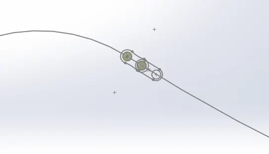
Extrude operation was carried out in several parts. The first extrude was done for the rollers with a mid-plane extrude with a value of 25 mm. Then the mid-region was extruded for 2 mm by giving an offset value of 9.5 mm. IN the next extrude the outer link plate was extruded for 2 mm thickness. All the extrudes were done without using merge solids options to make them into separate solids. Fillets of 0.5 mm were applied and the extruded parts were made into a pattern along the outline curve.
Then the pattern was created with a spacing of 30.26 mm and 65 instances to get the pattern for the first part.
Similarly, the pattern was carried out in all four parts and grouped in a particular folder such that it would be easy to mirror the links to the other side of the chain.
Oil Tank
After the second extrusion without merging the two solids, the combine command is used to select the operation type of common.
Pedal
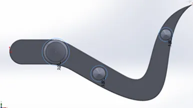
Mounting rods
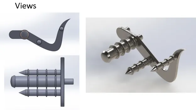
Foot Rest
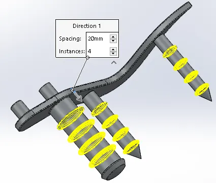
Rings created on the footrest and a linear pattern is applied.
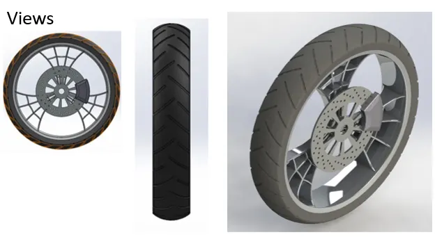
Front-wheel
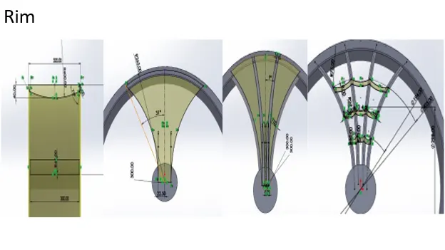
The outer rim is created using the revolute command and extrude command is used for the forks in the rim.
Cut out made to form a web pattern-like structure in the rim.
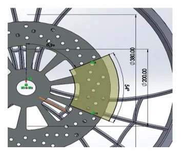
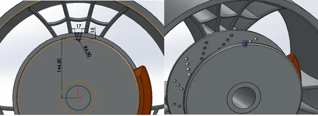
Holes of 8mm diameter with 4 instances were created on the rotor as shown in the above figure.
After the holes, a circular pattern is made with 20 instances. After the creation of holes, a cutout is made to reduce the weight of the rotor and material used for the manufacturing.
Caliper
Extrude command is used with 20mm in direction 1 and 15 mm in direction 2.
Chamfer has added the edges with distance-distance propagation.
Finally, for the sharp edges and corners, a suitable fillet radius is given.
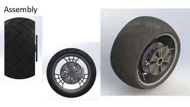
Tire for the rim is created in the same as the rim using the revolute command. The threading for the tire is given by the extrude cut with the defined sketch as shown in the figure.
Rear Wheel
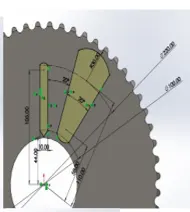
The design methodology of the rear wheel is the same as that of the front wheel. In the rear-wheel additional feature of the sprocket is added.
Sprocket and its teeth cut out
Sprocket Cut-out
Suitable fillets were given to avoid sharp edges in the thread cut out.
Front Fork
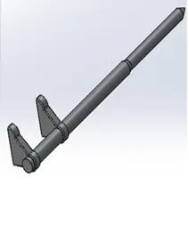
The front fork of the bike contains a handlebar, telescopic forks, and a headlamp of the bike.
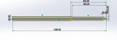
The modeling was started by making half of the telescopic fork using revolve feature.
Holding clamp
The sketch is extruded for a value of 20mm and suitable fillets were given to avoid sharp edges.
With the Extruded clamp a linear pattern is created at a distance of 240mm with 2 instances.
Head Lamp
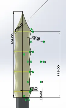
Handle Sketch
Brake Lever
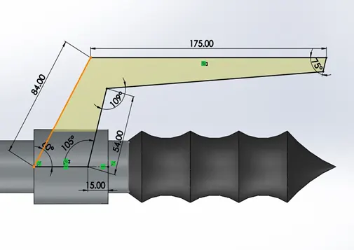
A suitable fillet was given to avoid sharp edges.
Brake Cable
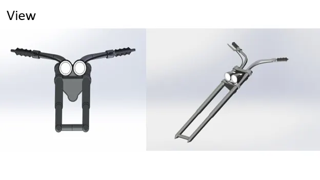
Till now one half of the fork is designed and then it is mirrored to get the complete fork.
Chassis or Frame of the chopper.
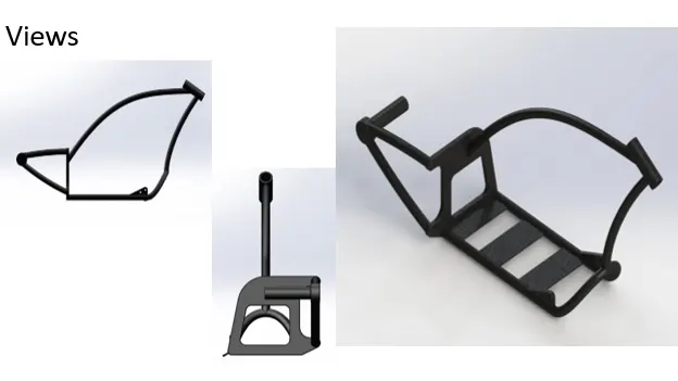
The chassis of the bike is like the mainframe of the vehicle on which all other components are mounted. Most of the chassis is made up of pipes which are modeled using the sweep of a closed profile along a suitable guide curve. Modeling was started by importing the blueprint picture for reference and starting with parallel members at the bottom.
Engine
The first step in the modeling of the engine was to get the blueprint picture as the guide for creating sketches. The process of getting it was the same as that of the chassis.
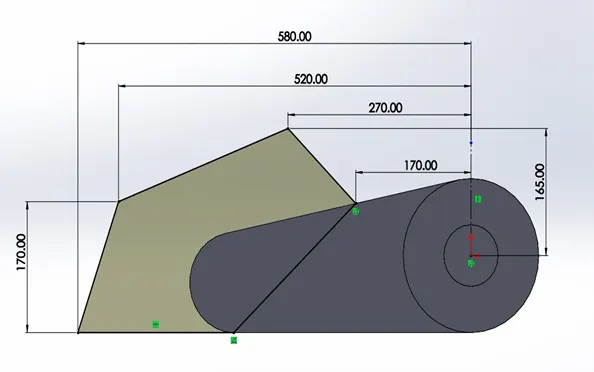
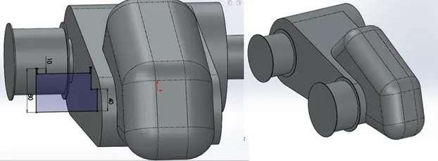
After that, another sketch as shown in the below figure was created and a midplane extrude of 150 mm was made out of it. This was made for the gearbox of the engine.
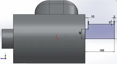
Side Pulley created using revolve command
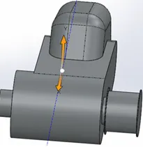
Similarly larger pulley is created
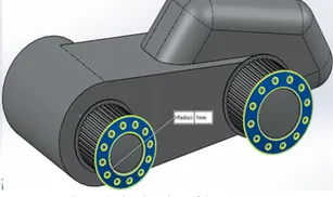
A step is created for the smaller and bigger pulley using a circular pattern with 40 instances on the smaller pulley and 45 instances on the bigger pulley.
Cut-out was made on both pulleys for the reduction in material and weight of the engine.
Starter Motor Sketch
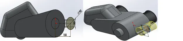
Engine Cylinder
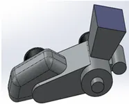
Engine Head.
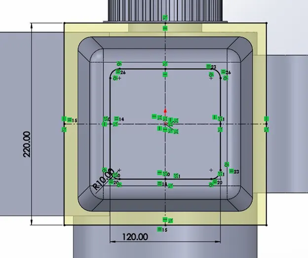
Using the sketch above the engine head is created using extrude command and chamfer is applied with distance-distance type.
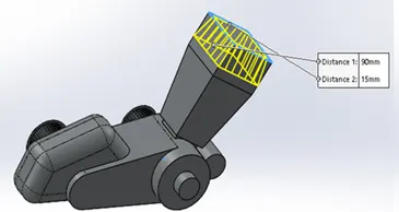
Engine Fins are created using the extrude cut command.
The fuel inlet is created in such a way that it is connected to the engine head.
Extrude command is used for a value of 20mm and fillets of suitable value are given to avoid sharp corners and edges.
Design of Sprocket
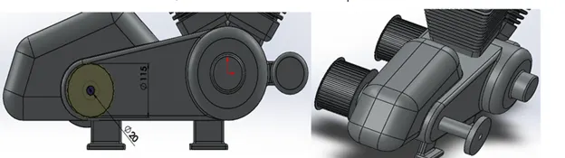
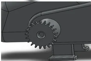
Teeth for the Sprocket
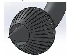
Design of air inlet to the engine
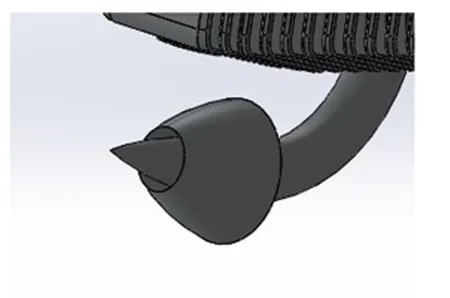
Cut out on the air filter for aesthetic look
Design of exhaust System
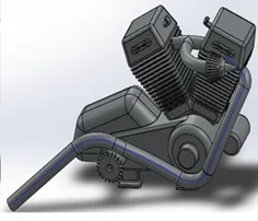
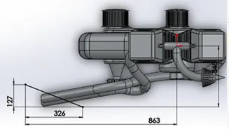
Similarly, exhaust from the second cylinder is created with appropriate dimensions using the projected curve feature.
The end portion of the exhaust is cut to get the aesthetical look.
Fuel pipe
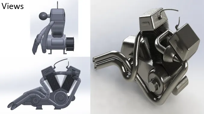
The Fuel Tank
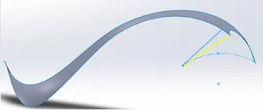
The fuel tank was mostly designed as a surface component and features of surface modeling were used extensively. The first step was to get a blueprint of the chopper for reference during the process.
The fuel tank is designed only one half and then mirrored with the midplane
The surface is created by sweep surface command following the path
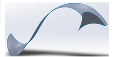
With the created surface the required shape of the fuel tank is obtained using the trim command.
Design of the surface at the side of the fuel tank
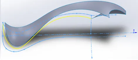
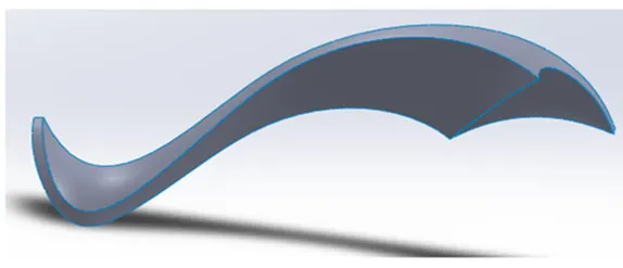
The designed fuel tank is mirrored with the mid-plane.
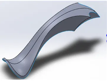
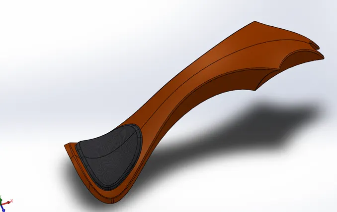
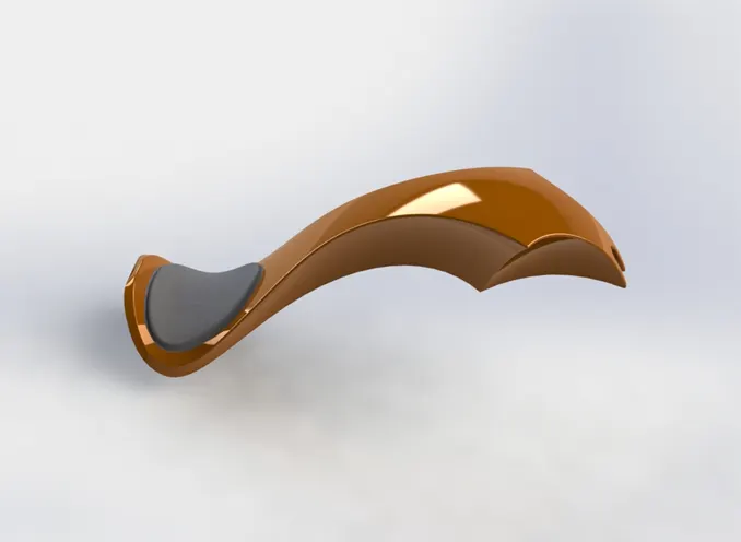
Design of the seat.
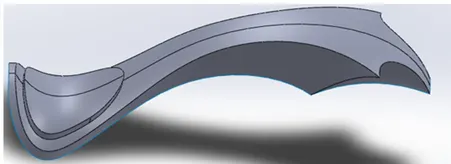
Extrude cut is made to accommodate the chassis frame.
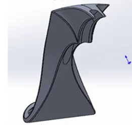
Suitable fillets are given to avoid sharp edges and corners.
Assembly of the American Chopper
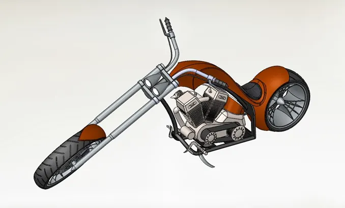
Steps followed:
1. A new assembly was created in the Solidworks and the first component to be imported was the chassis.
2. The next component inserted into the assembly was the engine.
3. The next component inserted into the assembly was the pedal. Three mates were applied to the part
4. Next, a mirrored component of the pedal was created for the other side of the bike.
5. The next component inserted into the assembly was the kickstand. Three mates were applied to it. The limit angle mate available under the advanced mate options was used to permit the rotation of the kickstand.
6. The next part added to the assembly was the transmission belt. Width, concentric, and angle mates were applied to position it properly in the assembly.
7. The next part added to the assembly was the oil tank.
8. Next component added to the assembly was the rear fender.
9. The next component added to the assembly was the rear fender.
10. After that the chain was added to the assembly. The mates applied to position the chain properly.
11. The next component inserted into the assembly was the fuel tank.
12. After that front fork was added to the assembly.
13. The next part added to the assembly was the front wheel. A plane in the middle of the front fork was created to mate the front wheel properly.
14. The final component inserted into the assembly was the front fender
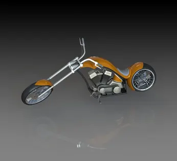
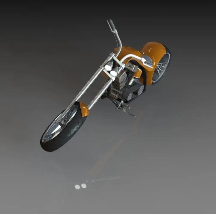
Rendering of the chopper
Google Drive Link: https://drive.google.com/drive/folders/1oTnMWlzGBXSHgC9zakHgwq2BQk3ksc_S?usp=sharing