Photo Realistic Rendering
AIM - Modelling and rendering of american chopper using solidworks.
OBJECTIVES -
- To create different parts of a American chopper in Solidworks using various types of sketches and features tools
- To assemble the different modelled parts to create the chopper.
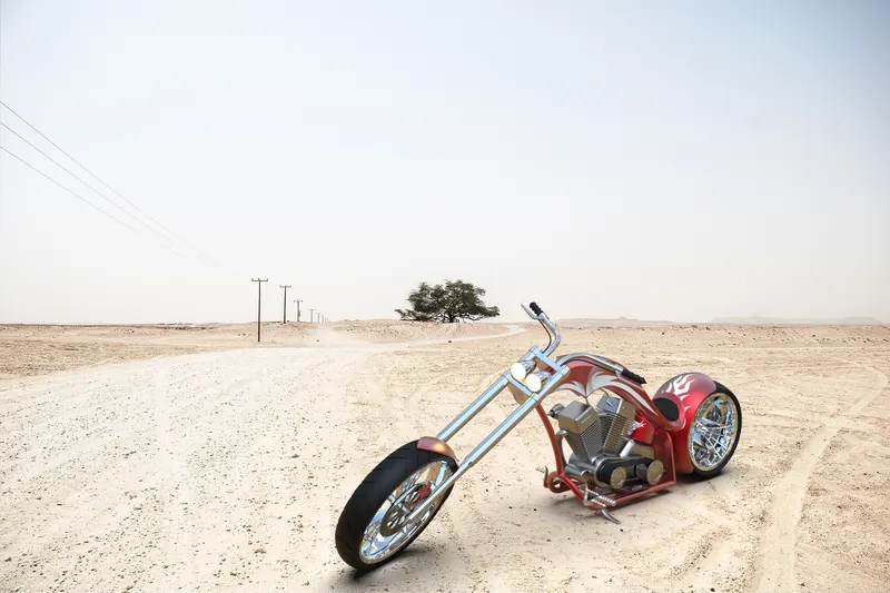
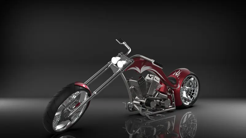
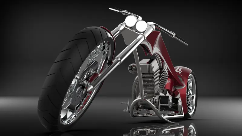
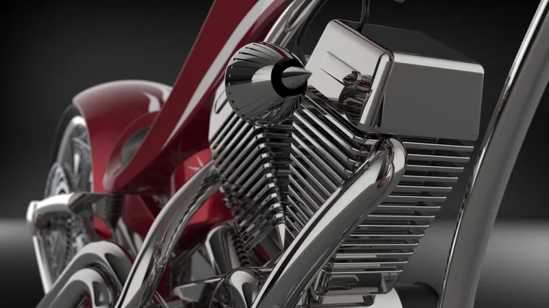
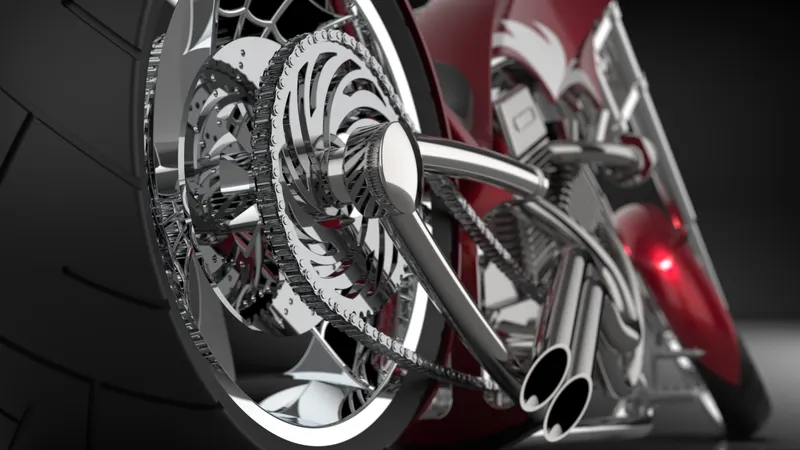
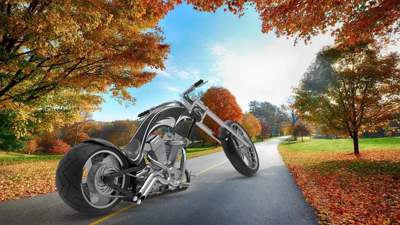
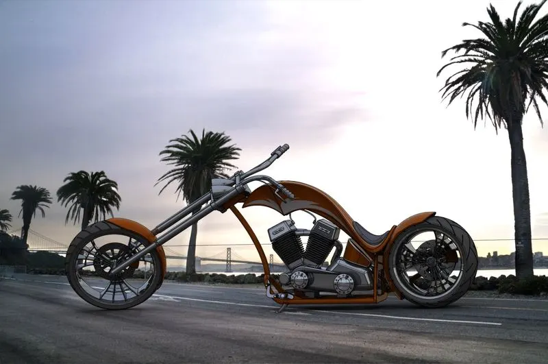
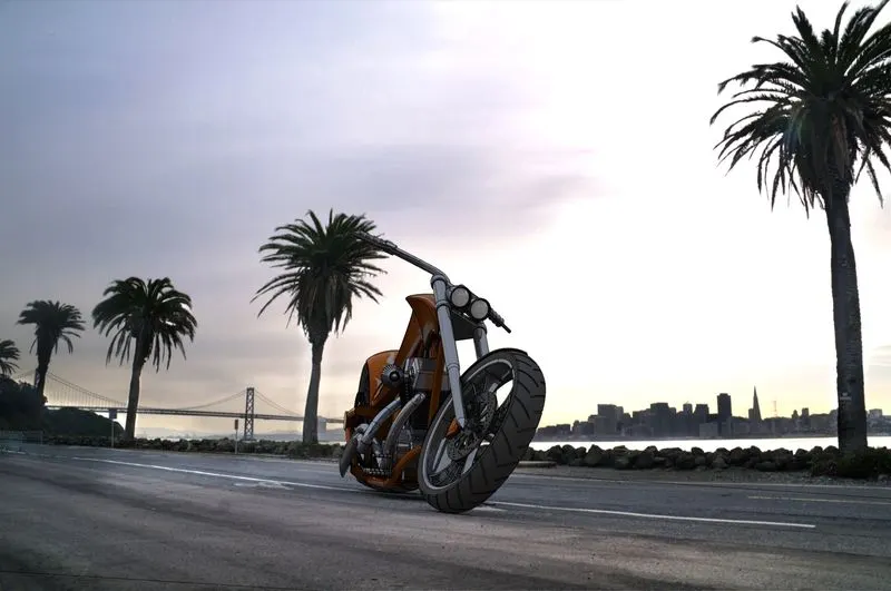
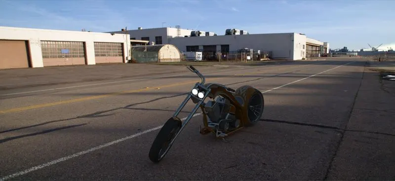
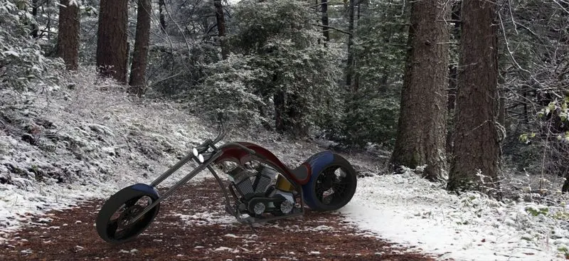
- To create photorealistic rendered images of the chopper using Solidworks Visualize.
INTRODUCTION -
The chopper was modelled using part modelling. Once after all the parts were modelled separately they were assembled to create the chopper. It consists of following parts,
- Chain
- Chassis
- Engine
- Front fender
- Front fork
- Front wheel
- Rear fender
- Rear wheel
- Oil tank
- Gastank
- kickstand
- Pedal
- Transmission belt
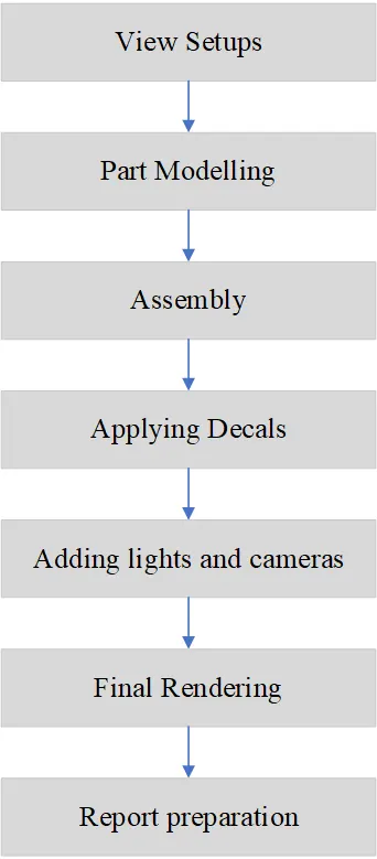
DESIGN METHODOLOGY
Flowchart
PART MODELLING -
The 3D part is the basic building block of any large scale design. Features are the individual shapes that, when combined, make up the part. One can also add some types of features to assemblies. Part documents can contain multiple solid bodies that we can manipulate the same way as single solid bodies.
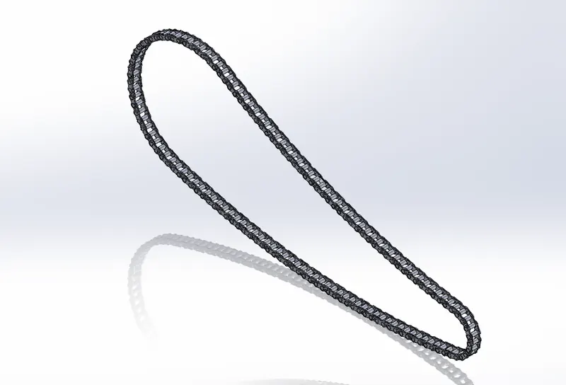
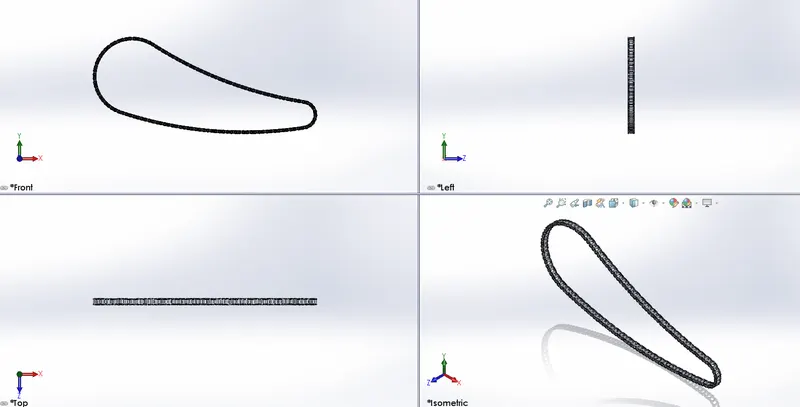
1. CHAIN
Motorcycle chains are part of the drive train to transmit the motor power to the back wheel. Properly lubricated chains can reach an efficiency of 98% or greater in the transmission. Unlubricated chains will significantly decrease performance and increase chain and sprocket wear.
Commands used: Following were the commands used to model the part,
- 2D sketch
- Fillet
- Smart Dimensions
- Appearance
- Extruded boss/base
Image of the modelled part:
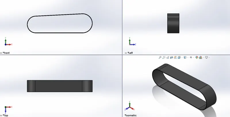
2.TRANSMISSION BELT
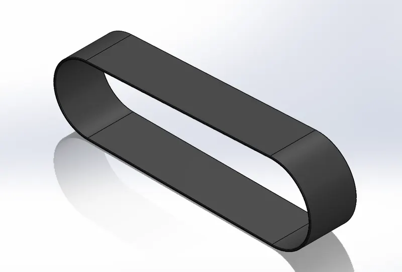
A belt is a loop of flexible material used to link two or more rotating shafts mechanically, most often parallel. Belts may be used as a source of motion, to transmit power efficiently or to track relative movement. Belts are looped over pulleys and may have a twist between the pulleys, and the shafts need not be parallel.
Commands used: Following were the commands used to model the part,
- 2D sketch
- Fillet
- Smart Dimensions
- Appearance
- Extruded boss/base
- Curve driven pattern
- Mirror feature
- Body-Delete/keep
Image of the modelled part:
3.FENDERS
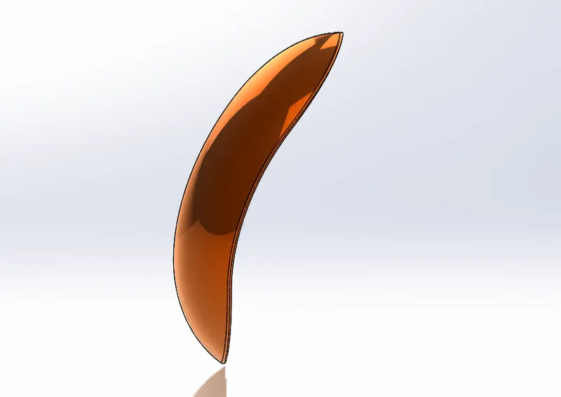
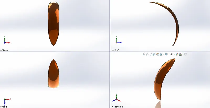
A fender is the part of a vehicle that protects and frames its wheels and keeps mud from splashing it. Most modern vehicles have fenders on their front and back wheels.
FRONT FENDER
It is for the front wheel.
Commands used: Following were the commands used to model the part,
- 2D sketch
- Fillet
- Smart Dimensions
- Appearance
- Split
- Revolve
Image of the modelled part:
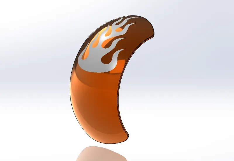
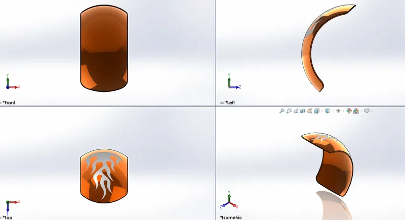
REAR FENDER
It is for the rear wheel. It also comprises of a decal.
Commands used: Following were the commands used to model the part,
- 2D sketch
- Fillet
- Smart Dimensions
- Appearance and decals
- Split
- Revolve
- Shell
Image of the modelled part:
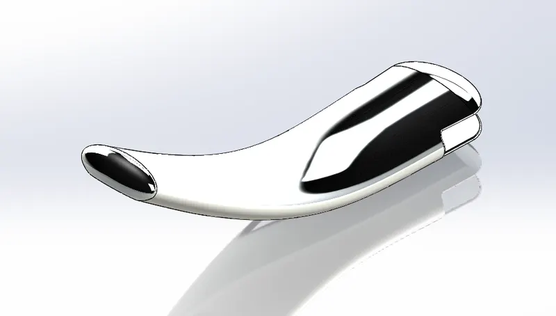
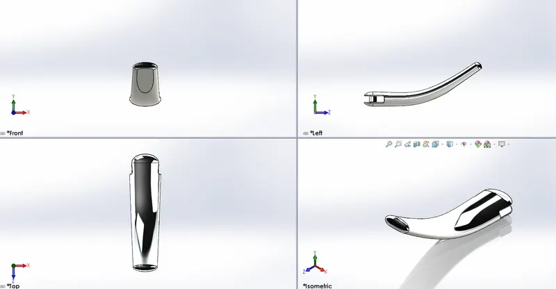
4.KICK-STAND
It is a metal rod attached to a bicycle or motorcycle, lying horizontally when not in use, that may be kicked into a vertical position to support the vehicle when it is stationary.
Commands used: Following were the commands used to model the part,
- 2D sketch
- Fillet
- Smart Dimensions
- Appearance
- Split
- Lofted boss/base
- Extruded boss/base
- EXtruded cut
- Dome
Image of the modelled part:
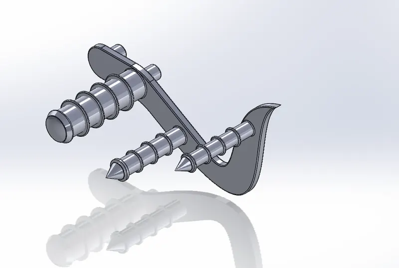
5.PEDAL
It is a foot lever or treadle by which a part is activated in a mechanism.
Commands used: Following were the commands used to model the part,
- 2D sketch
- Fillet
- Smart Dimensions
- Appearance
- Chamfer
- Revolved boss/base
- Extruded boss/base
- Linear Pattern
- Dome
Image of the modelled part:
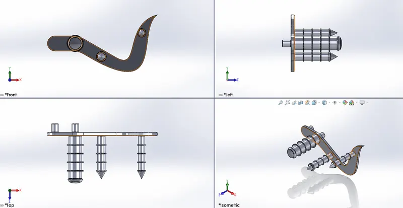
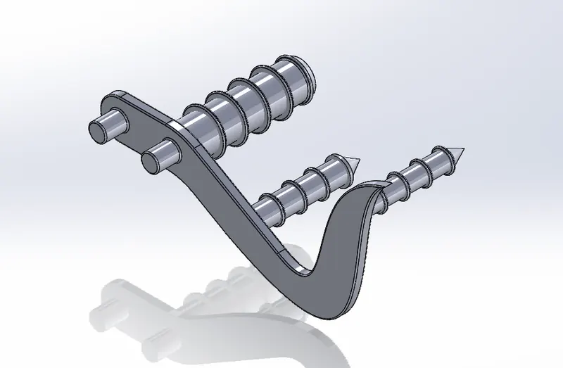
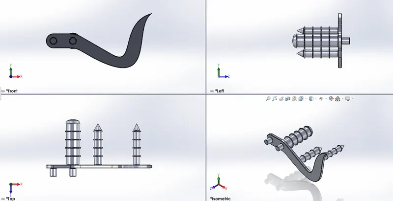
PEDAL LHS
It is the mirrored part of the pedal across the mid plane.
Commands used: Following were the commands used to model the part,
- Mirror feature
Image of the part:
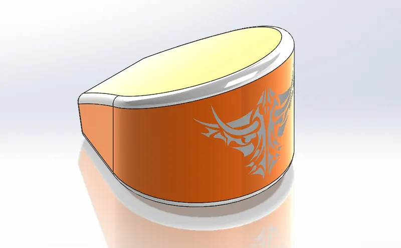
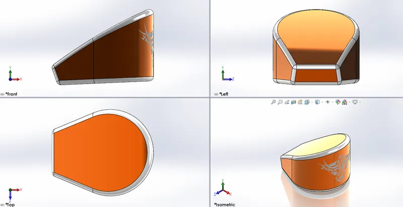
6.OIL TANK
It is a container for holding or storing oil. Oil tank also comprises of a decal.
Commands used: Following were the commands used to model the part,
- 2D sketch
- Fillet
- Smart Dimensions
- Appearance and decals
- Extruded boss/base
- Combine
- Shell
Image of the modelled part:
7.WHEELS
It is a circular object that revolves on an axle and is fixed below a vehicle or other object to enable it to move easily over the ground.
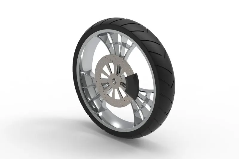
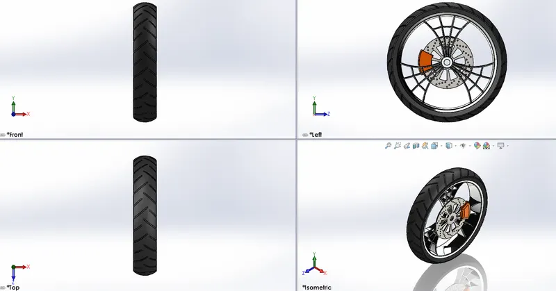
FRONT WHEEL
It is at the front of the vehicle. It consists of following components,
- Rim
- Disc brake (Rotor)
- Tyre
- Caliper
Commands used: Following were the commands used to model the parts,
- 2D sketch
- Offset entities
- Fillet
- Trim entities
- Smart Dimensions
- Appearance
- Chamfer
- Mirror Entities
- Extruded cut
- Revolved cut
- Combine
- Circular pattern
- Extruded boss/base
- Revolved boss/base.
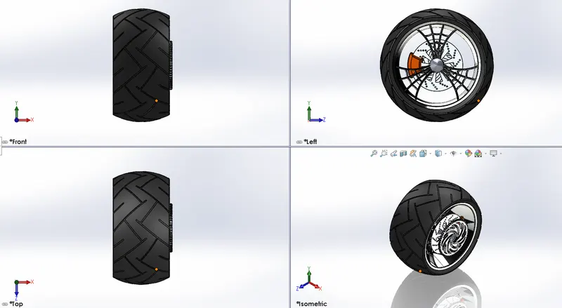
Images of modelled part:
REAR WHEEL
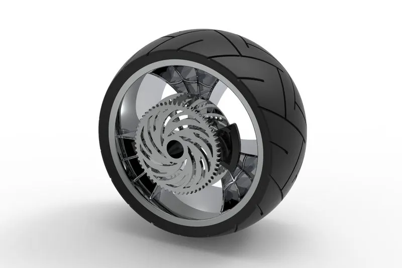
It is at the back of the vehicle. It has following components in it,
- Rim
- Disc brake (Rotor)
- Tyre
- Sprocket
- Caliper
Commands used: Following were the commands used to model the part,
- 2D sketch
- Offset entities
- Fillet
- Trim entities
- Smart Dimensions
- Appearance
- Chamfer
- Mirror Entities
- Combine
- Extruded cut
- Revolved cut
- Circular pattern
- Extruded boss/base
- Revolved boss/base.
Images of modelled part:
8.FRONT FORK
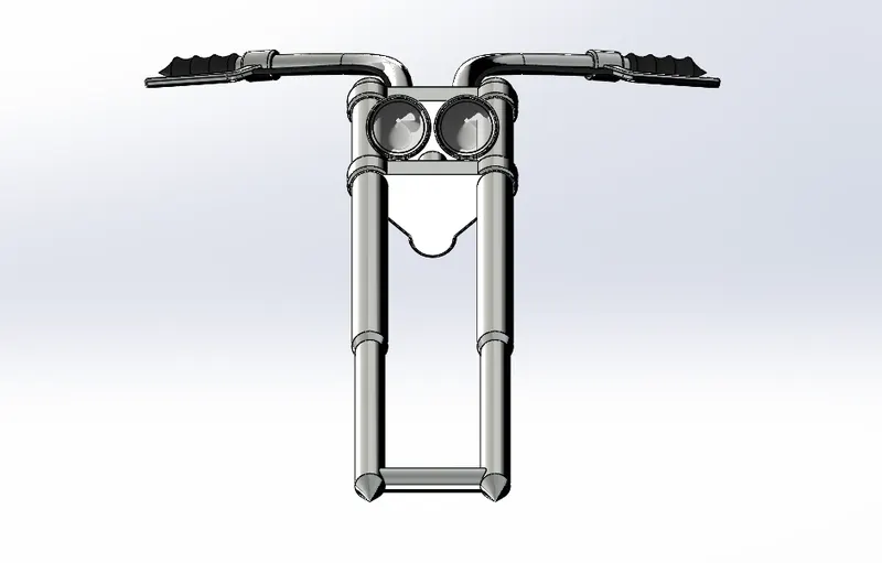
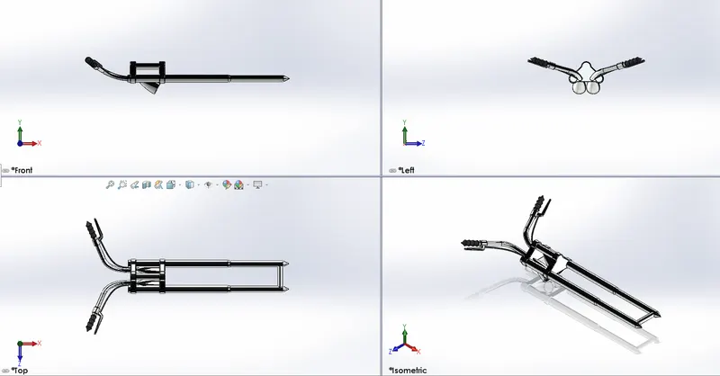
The front fork is a suspension component for either bicycle fork or motorcycle fork. The forks can be most easily understood as simply large hydraulic shock absorbers with internal coil springs. They allow the front wheel to react to imperfections in the road while isolating the rest of the motorcycle from that motion.
Commands used: Following were the commands used to model the part,
- 2D sketch
- Fillet
- Trim entities
- Smart Dimensions
- Appearance
- Dome
- Mirror Entities
- Body-Move/Copy
- Combine
- Extruded cut
- Revolved cut
- Circular pattern
- Linear pattern
- Projected curve
- Reference Plane
- Extruded boss/base
- Swept boss/base
- Revolved boss/base.
Image of modelled part:
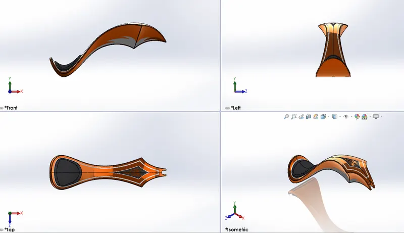
9.GAS TANK or FUEL TANK
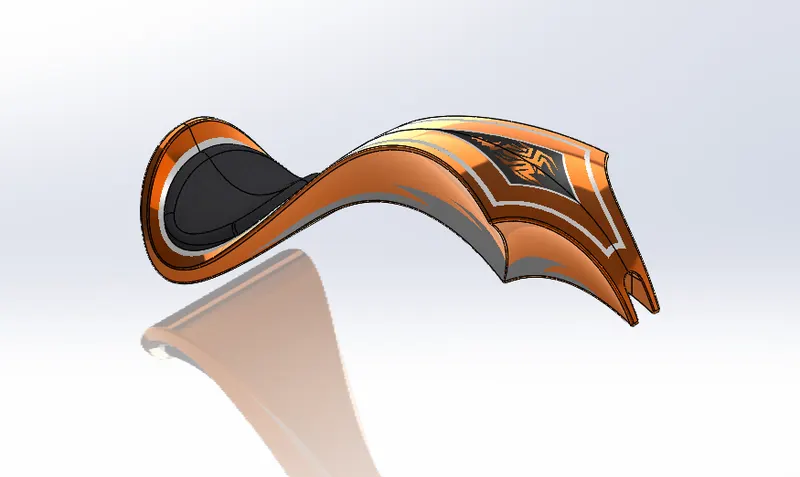
A fuel tank is a safe container for flammable fluids. Though any storage tank for fuel may be so called, the term is typically applied to part of an engine system in which the fuel is stored and propelled (fuel pump) or released (pressurized gas) into an engine. Fuel tanks range in size and complexity from the small plastic tank of a butane lighter to the multi-chambered cryogenic Space Shuttle external tank.
This fuel tank consists of three decals.
Commands used: Following were the commands used to model the part,
- 2D sketch
- Sketch picture
- Fillet
- Trim
- Smart Dimensions
- Appearance and decals
- Shell
- Mirror
- Split line
- Projected curve
- Reference Plane
- Surface trim
- Swept cut
- Lofted surface
- Boundary surface
- Swept surface
- Extruded surface
- Knit surface.
Image of modelled part:
10.ENGINE
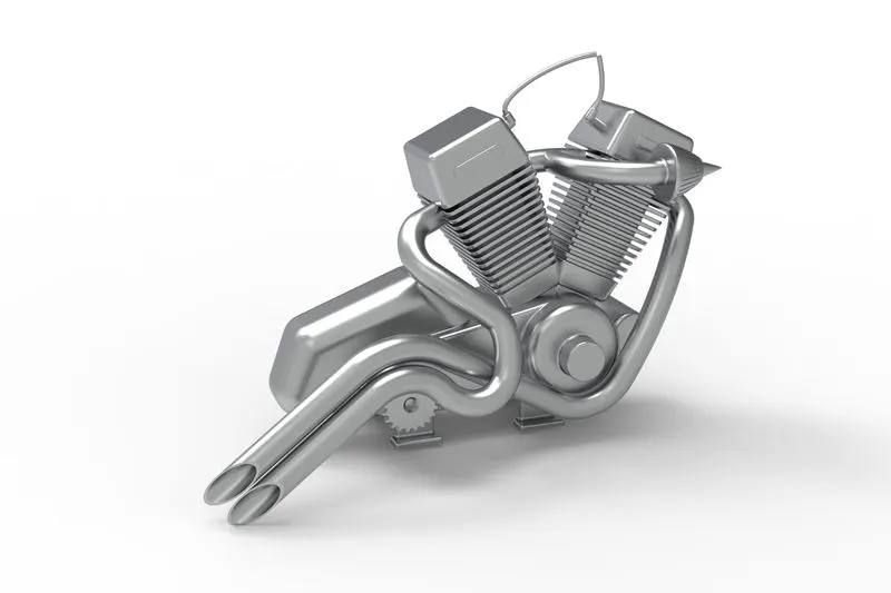
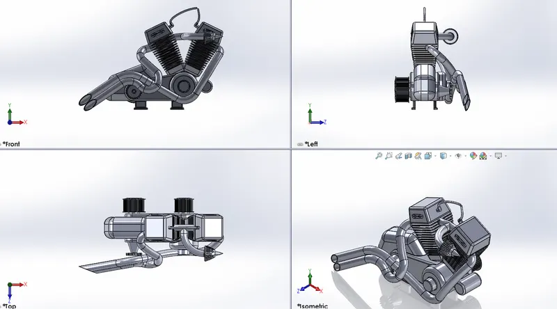
A motorcycle engine is an engine that powers a motorcycle. Motorcycle engines are typically two-stroke or four-stroke internal combustion engines, but other engine types, such as Wankels and electric motors, have been used.
Commands used: Following were the commands used to model the part,
- 2D sketch
- Sketch picture
- Fillet
- Trim
- Smart Dimensions
- Appearance
- Chamfer
- Mirror
- Split
- Combine
- Dome
- Extruded cut
- Circular pattern
- Linear pattern
- Projected curve
- Composite curve
- Reference Plane
- Extruded boss/base
- Revolved boss/base
- Swept boss/base.
Images of the modelled part:
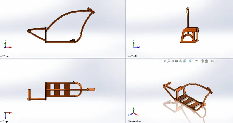
11.CHASSIS
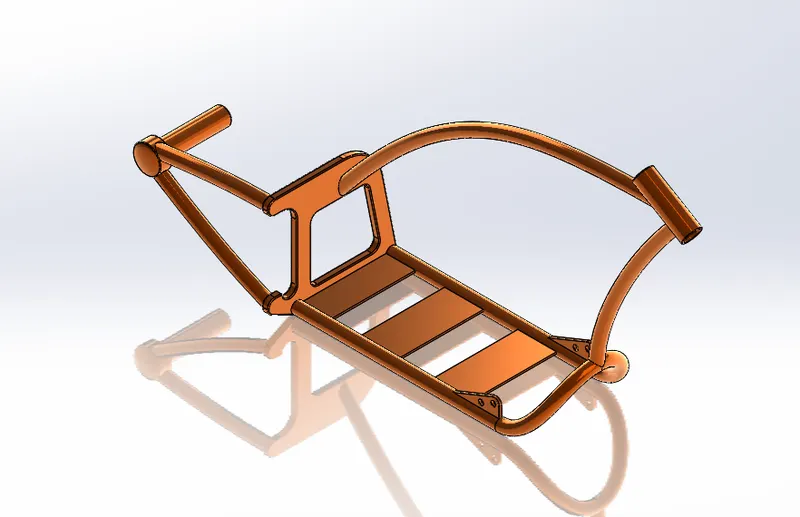
It is a vehicle frame, the underpart of a motor vehicle, on which the body is mounted; if the running gear such as wheels and transmission, and sometimes even the driver's seat, are included, then the assembly is described as a rolling chassis.
Commands used: Following were the commands used to model the part,
- 2D sketch
- Sketch picture
- Fillet
- Split
- Smart Dimensions
- Appearance
- Chamfer
- Mirror
- Combine
- Dome
- Extruded cut
- Projected curve
- Reference Plane
- Extruded boss/base
- Revolved boss/base
- Swept boss/base.
Images of the modelled part:
ASSEMBLY OF AMERICAN CHOPPER
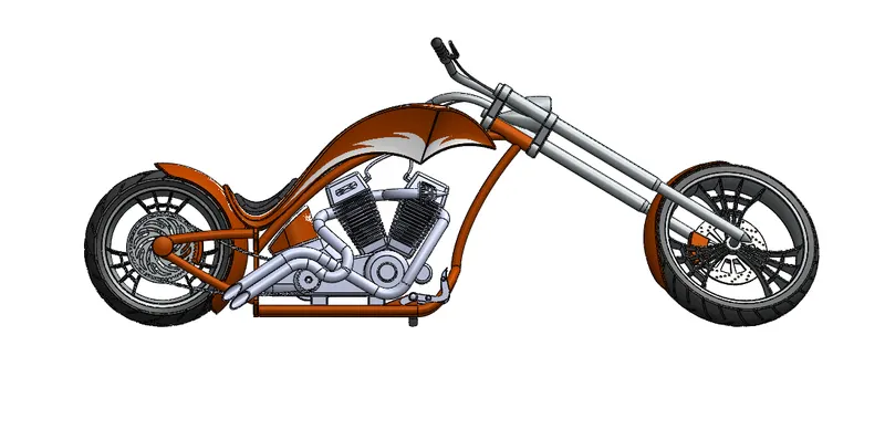
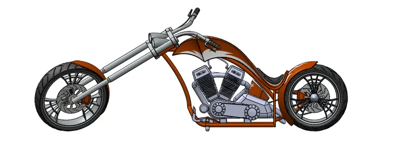
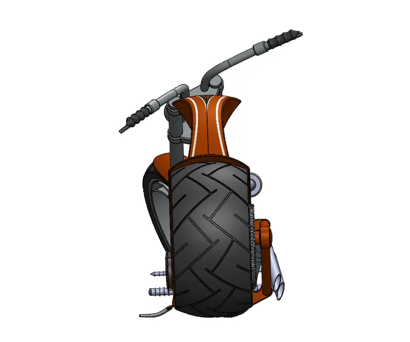
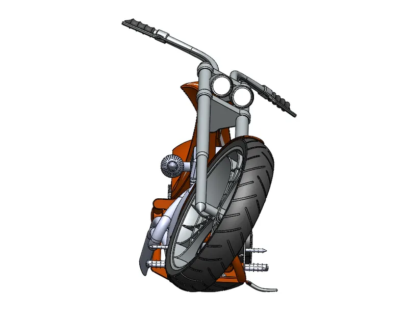
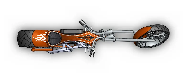
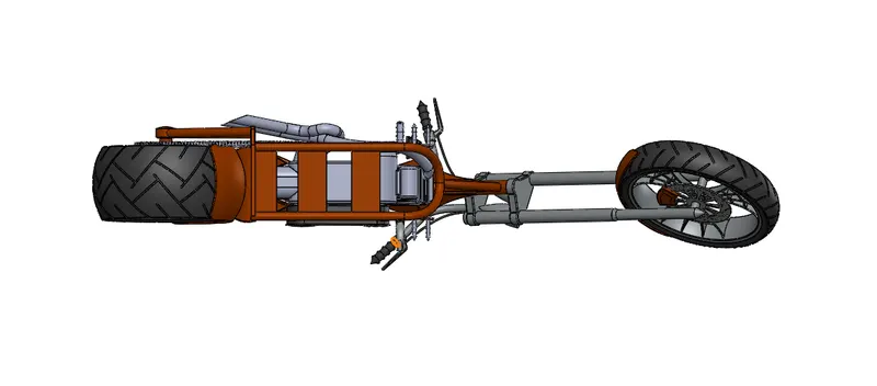
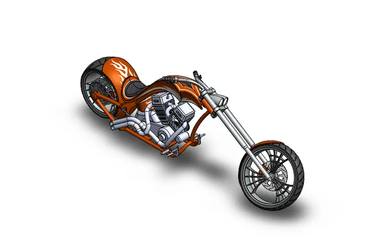
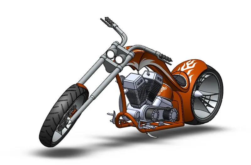
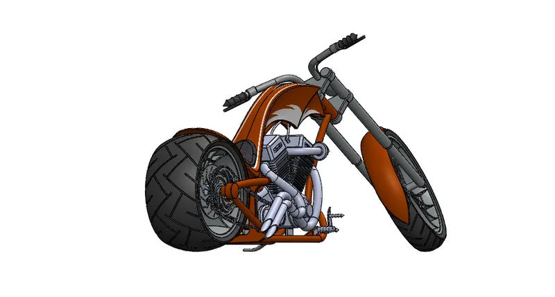
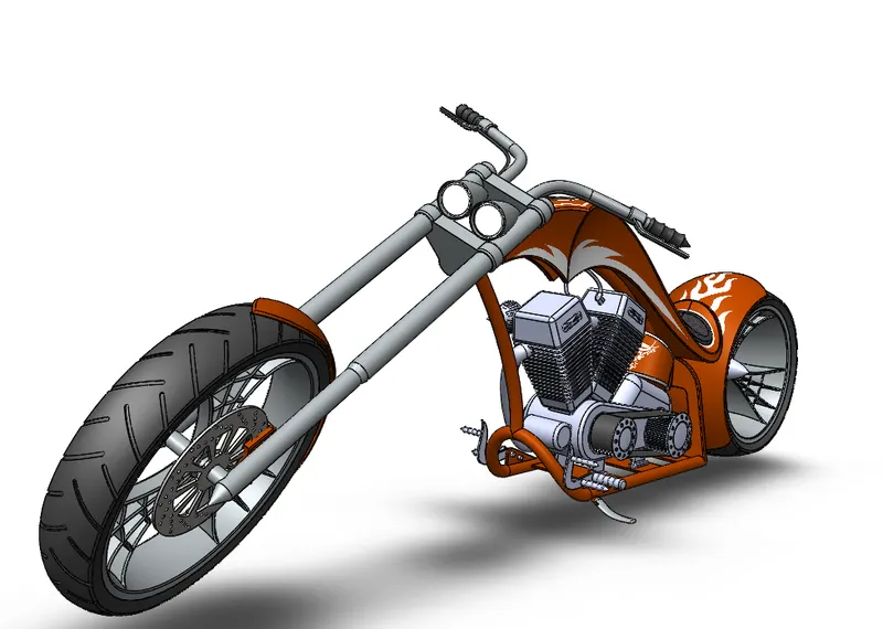
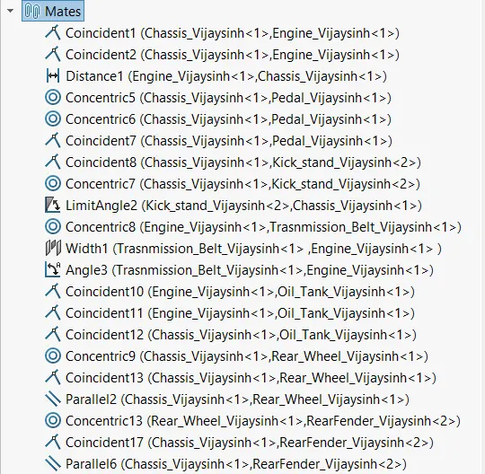
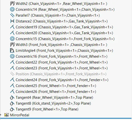
All the modelled parts were inserted one by one in the assembly. The parts were inserted randomly in the assembly environment and were given manual mates by taking chassis as the reference so that all the parts move with respect to chassis only when the chassis floats.
Images of the assembly: Following are the images of the chopper assembly in different views,
Front view
Back view
Left side view
Right Side view
Top view
Bottom view
Isometric view
CAMERA ANGLE VIEW
camera 1
camera 2 (side camera)
Render camera
Mates applied in chopper
Renders
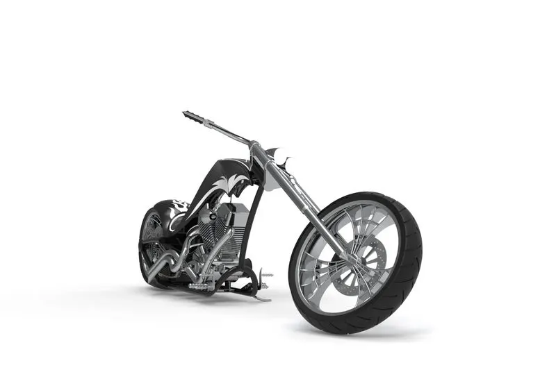
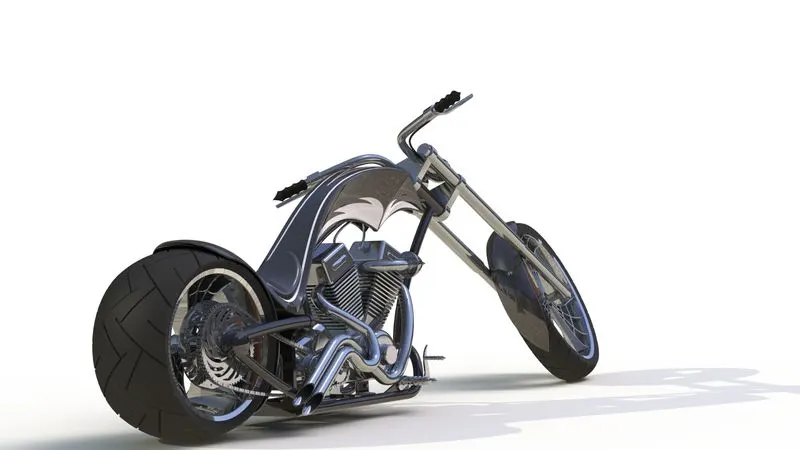
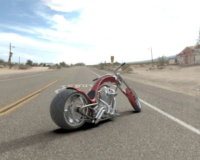
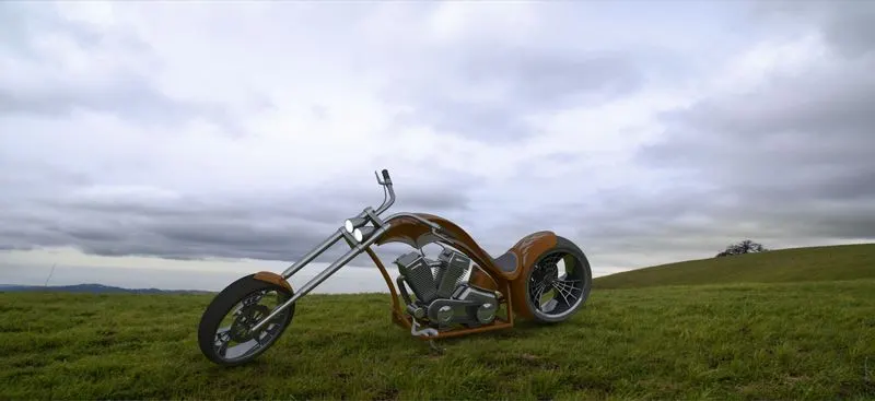
For rendering there are two tools offered by solidworks
- Photo view 360
- Solidworks visualise
both are the great tools but solidworks visualise offers a lot of control over renders. In photo view 360 very limited option are available for renders. In Solidworks visualise we can post process the results to obtain more realastic view.
Low Quality Renders (Using GPU only)
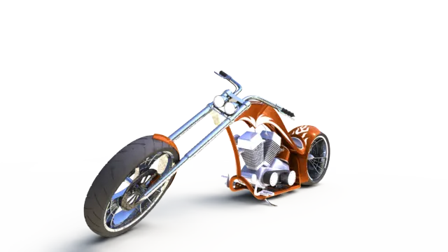
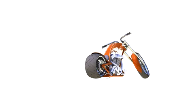
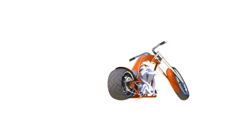
High Quality Renders (CPU and GPU both in Working)
Conclusion
All the parts of the American chopper were modelled and the assembly was created using Solidworks and the photorealistic renders of the chopper were created using Photo view 360 and Solidworks Visualize.