Photo Realistic Rendering
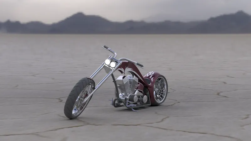
DESGIN OF AMERICAN CHOPPER
Objectives:-
- To learn product design in solidworks software.
- To learn the solidworks software as a design tool in industrial manner.
- The objective of this project is to create a model of different exterior modeling environment using solidworks.
Introduction:-
American chopper is an American reality television series that airs on Discovery Channel,produced by Pilgrim Films & Television. The series centers on Paul Teutul Sr.(frequently called Senior),and his son Paul Teutul Jr.(also known as Paulie or simply Junior),who manufacture custom chopper-style motorcycles.
Part Modeling:-
Modeling in general means to create a virtual prototype of an item it can be used for various purposes. Consider an engine of a bike. It has hundreds of parts. each parts can be modeled separatly and then can be assembled together to get final product.This type of modeling is called part modeling.
Assembly:-
An assembly is an collection of independent model parts which are brought together in an assembly and make it final product.
Parts of American Chopper:-
- Transmission Belt.
- Kick Stand.
- Front Fender.
- Rear Fender.
- Oil Tank.
- Chain.
- Pedal.
- Front Wheel.
- Rear Wheel.
- Front Fork.
- Chassis.
- Engine.
- Gas Tank.
Explaination:-
1. Transmission Belt:
The main purpose of transmission belt is used to transmit power which is developed inside the engine to gear box with maximum efficiency.
- Features used to create a transmission Belt are:
- Sketch.
- Offset.
- Extrude.
- Fillet.
- Appearance.
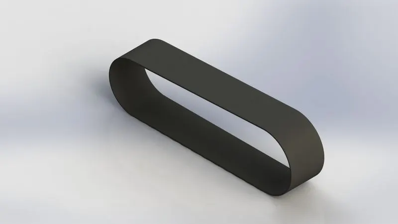
TRANSMISSION BELT
2. Kick Stand:-
A kick stand is a device on a bike that allows the bike to be kept upright without leaning against another object or the aid of a person. A kick stand is usually a piece of metal that flips down from the frame and makes contact with the ground.Kick stand give support to the full body of american chopper.
- Features used to create a Kick Stand are:
- Sketch.
- Loft.
- Dome.
- Extrude Boss.
- Extrude Cut.
- Fillet.
- Split.
- Appearance.
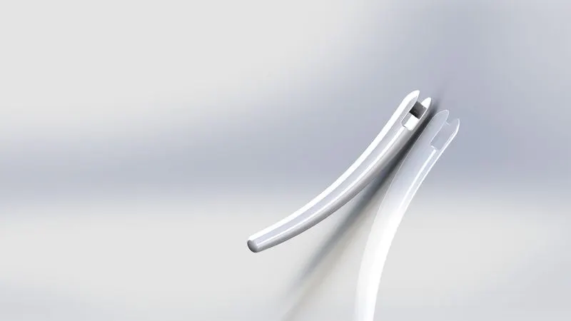
KICK STAND
3. Front Fender:-
Fornt fender primary purose is to prevent sand,mud,rocks,liquids,and other road spray from being thrown into the air by the rotating tire.
- Features used to create a Front Fender are:
- Sketch.
- Offset entities.
- Trim entities.
- Revolve.
- Dynamic mirror.
- Split.
- Fillet.
- Appearance.
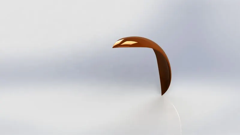
FRONT FENDER
4. Rear Fender:-
A rear fender is essentially a covering for your bike tires that protacts you from the rain. Riding with fender will be prevent the rain from splashing a streak of muddy water up your back.
- Features used to create a Rear Fender are:
- Sketch.
- Offset entities.
- Trim entities.
- Revolve.
- Appearance.
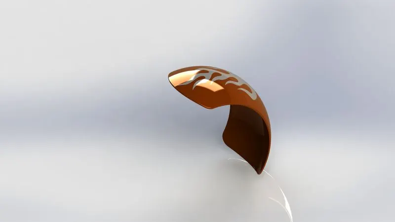
REAR FENDER
5. Oil Tank:-
The oil tank is hollow section,and main purpose of oil tank is used to store the oil and supply the oil to engine while start the vehicle.
- Features used to create a Oil Tank are:
- Sketch.
- Boss extrude.
- Combine.
- Shell.
- Fillet.
- Appearance.
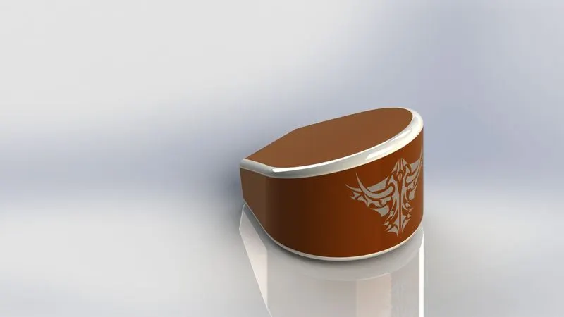
OIL TANK
6. Chain:-
Chain drive is a way of transmitting mechanical power from one place to another.It is often used to convey power to the wheels of a vehicle.Most often,the power is conveyed by a roller chain,known as the drive chain or transmission chain.
- Features used to create a Chain are:
- Sketch.
- Boss extrude.
- Fillet.
- Curve pattern.
- Mirror.
- Appearance.
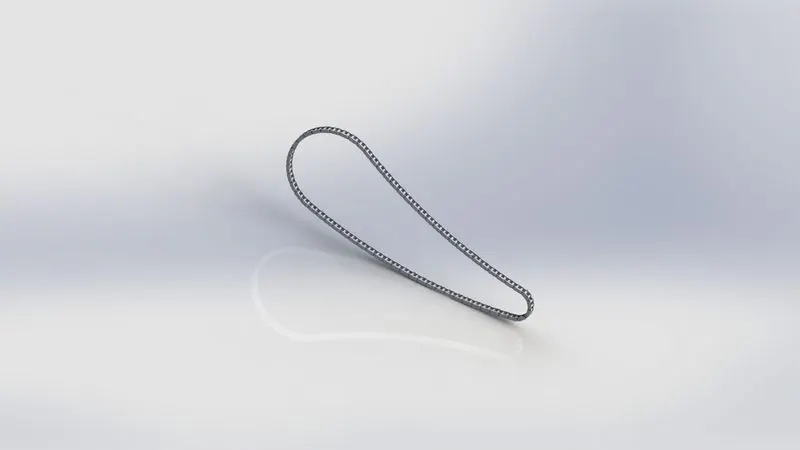
CHAIN
7. Pedal:-
The main purpose of pedal is that place the leg on top of that for resting position and sometimes used for changing the gears by keeping leg on pedal.
- Features used to create a Pedal are:
- Sketch.
- Boss extrude.
- Revolve.
- Dome.
- Fillet.
- Chamfer.
- Linear pattern curve.
- Appearance.
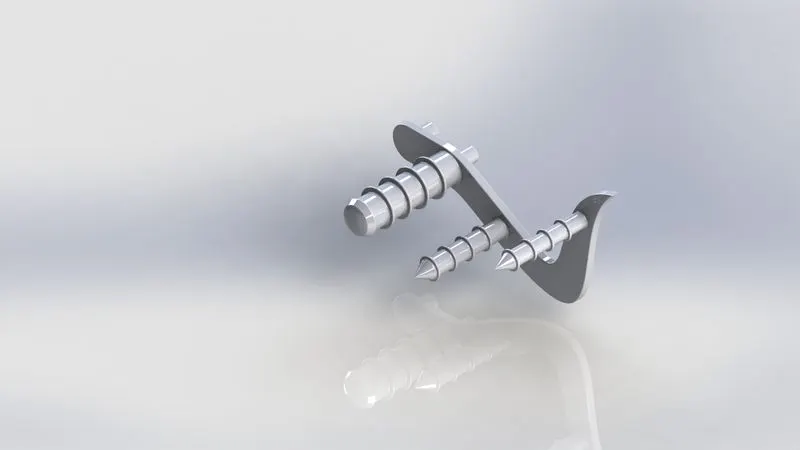
PEDAL
8. Front Wheel:-
Motorcycle wheels are made to cope with radial and axail forces. They also provide a way of mounting other critical components such as brakes,final drive and suspension.Traditionally motorcycles used wire-spoked wheels with inner tubes and pneumatic tyres.
- Features used to create a Front Wheel are:
- Sketch.
- Revolve.
- Boss extrude.
- Cut extrude.
- Circular pattern.
- Linear pattern.
- Combine.
- Trim.
- Fillet.
- Chamfer.
- Appearance.
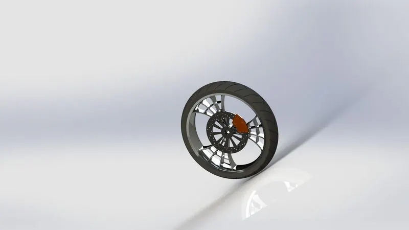
FRONT WHEEL
9. Rear Wheel:-
The chain is connected between the engine and rear wheel to drive the vehicle which the power is develop inside the engine.The rear wheel has disc brake and sprocket attachment.
- Features used to create a Rear Wheel are:
- Sketch.
- Revolve.
- Cut extrude.
- Boss extrude.
- Circular pattern.
- Combine.
- Revolve cut.
- Fillet.
- Chamfer.
- Appearance.
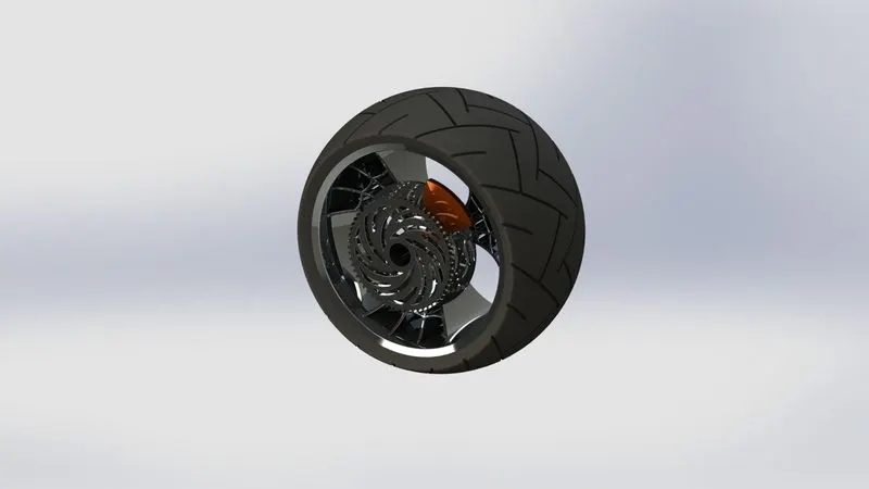
REAR WHEEL
10. Front Fork:-
The front fork prevents excessive weight on the front wheel during drastic sudden applications the brake,softens bumping when driving on rough road surfaces.The front fork maintains proper damping through traction with the road surface.
- Features used to create a Front Fork are:
- Sketch.
- Revolve.
- Boss extrude.
- Fillet.
- Linear pattern.
- Cut extrude.
- Dome.
- Revolve cut.
- Project curve.
- Mirror.
- Combine.
- Sweep.
- Split.
- Appearance.
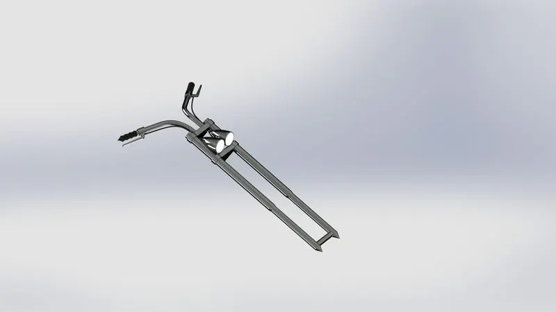
FRONT FORK
11. Chassis:-
A motorcycle's chassis or frame forms its skeleton.All the components of a bike,like the front fork,wheels,oil tank,seat,gas tank etc,are atttached to this base structure which lends a bike it's strength and ability to handle well.Bike frames come in a variety of materials and shapes,based on the budgetary and performance-related limits of the end product.
- Features used to create a Chassis are:
- Sketch.
- Convert entities.
- Project curve.
- Offset.
- Trim.
- Sweep.
- Split.
- Revolve.
- Cut extrude.
- Fillet.
- Combine.
- Mirror.
- Chamfer.
- Dome.
- Appearance.
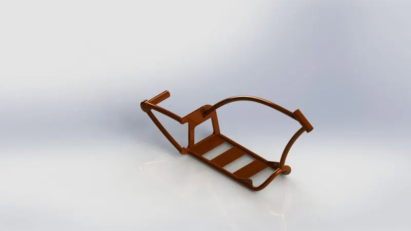
CHASSIS
12. Engine:-
The engine is prime mover of any vehicle;it converts the chemical energy into heat energy by burning the air fuel mixture inside the engine cylinder.Bike engines are typically two-stroke or four-stroke internal combustion engines,but other engine types,such as Wrankels and electric motors,have been used.Then heat energy is converted into mechanical energy by rotating the parts like flywheel,clutch,gearbox etc... then power is transmitted to rear wheel.
- Features used to create a Engine are:
- Sketch.
- Boss extrude.
- Revolve.
- Fillet.
- Circular pattern.
- Dome.
- Cut extrude.
- Chamfer.
- Linear pattern.
- Mirror.
- Swept.
- Project curve.
- Split.
- Appearance.
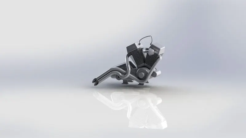
ENGINE
13. Gas Tank:-
The main purpose of gas tank is used to store the gas.It supplies the gas when engine started.
- Features used to create a Gas Tank are:
- Sketch.
- Surface sweep.
- Surface trim.
- Poject curve.
- Surface loft.
- Surface boundary.
- Surface knit.
- Split line.
- Mirror.
- Surface extrude.
- Fillet.
- Cut extrude.
- Shell.
- Appearance.
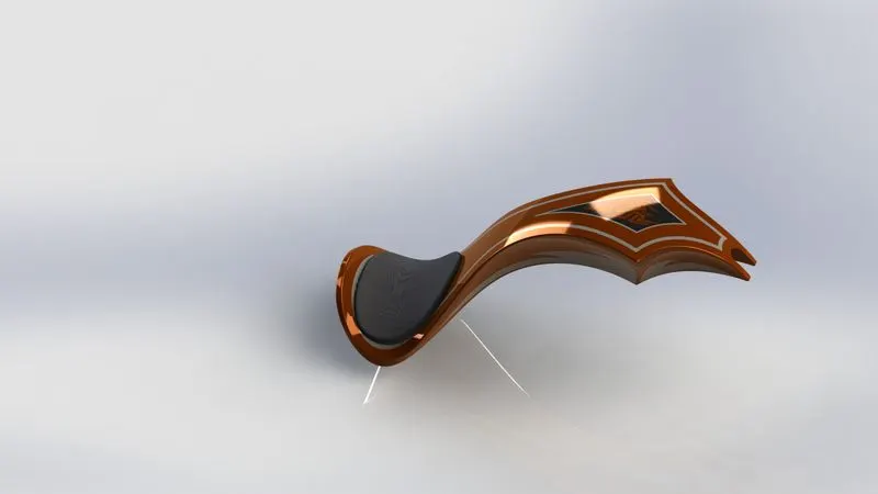
GAS TANK
Assembly:-
Assembly is tool in which all seperated parts or modeled parts brought together and make it single or final product is known as assembly.
- Features used to create a Assembly are:
- Insert parts.
- Mates.
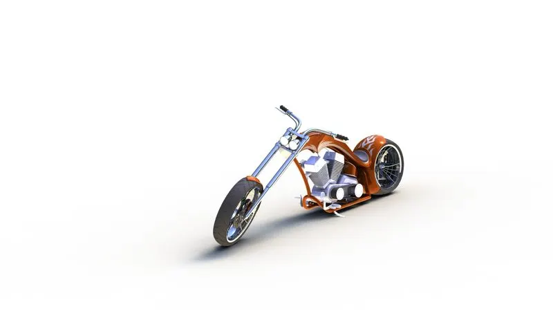
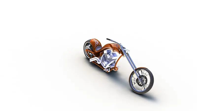
FINAL ASSEMBLY OF AMERICAN CHOPPER
Rendering:-
Rendering is a process to bring our model into realistic way with environment.Rendering give result how our product look in real.
There are two type of methods will be used such as:
- Photoview 360.
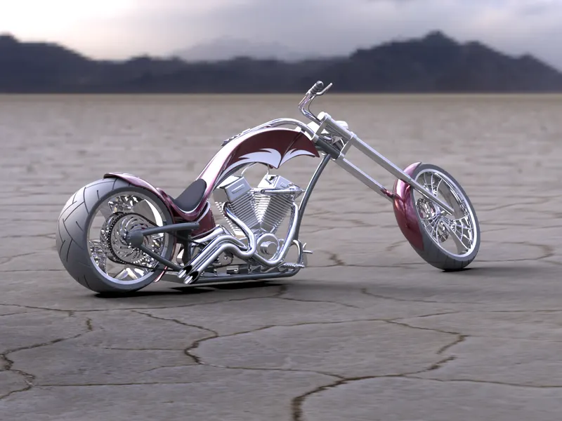
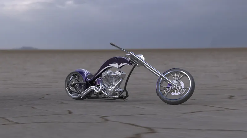
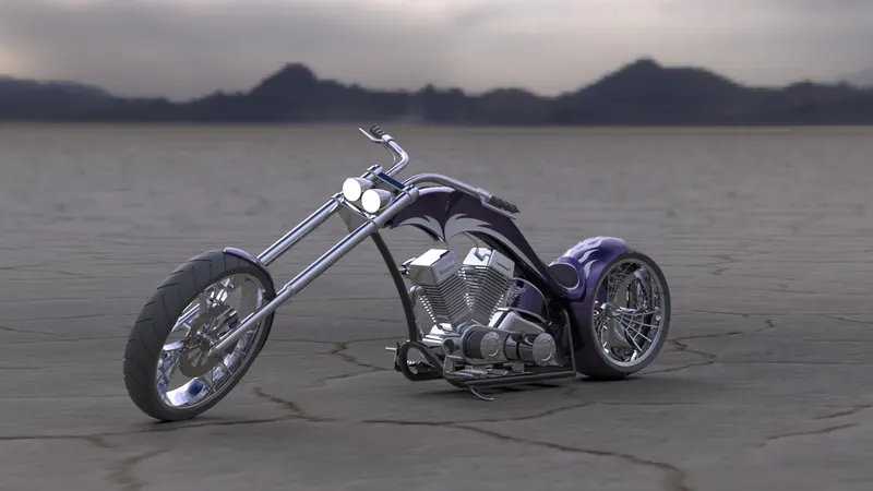
- Solidworks visualize.
Photoview 360:-
It will be done in solidworks itself. It helps as to add light,camera,decals and scene.
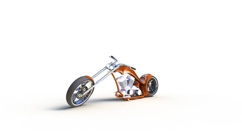
PHOTO VIEW 360
Solidworks visualize:-
This is very good solidwork product it's give a perfect render image then photoview 360.It show us full real view of product.
SOLIDWORKS VISUALIZE
Conclusion:-
- Finally completed product design in solidwork software.
- The part model its design as per given dimension.
- Assembly made with proper mate.
- Rendering process done using both tool photoview 360 and solidworks visualize.