Photo Realistic Rendering
1. Assembly of the chopper:
Objective:
The main objective of the project is to design and model of American chopper bike as per manual dimensions and represent it with a realistic look using rendering tools.
Introduction:
American chopper bike is an assembly of different components such as Fork, Engine, Gas tank, Oil tank, Front & Rear wheel, Chain& Belt connection, Exhaust manifold etc.
All the components were designed individually and then assembled to form a chopper bike.
Design Methodology:
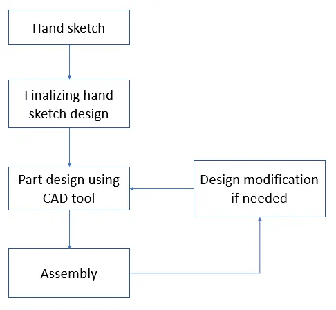
Transmission Belt:
The transmission belt is used to transmit power from the engine to the transmission box.
Feature used:
- Extruded boss
- Fillet
Belt is designed by drawing the belt sketch on a Front plane and Extruded boss feature is used to convert that 2d sketch into 3d model.
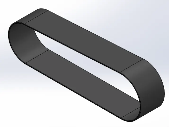
Front Fender:
The front fender is used to prevent sand, mud, rocks, liquids, and other roads spray from being thrown into the air by the rotating tire. While the vehicle is in running condition due to forward motion the sand and dust on the road will go backward due to the force and causes minor defects in the engine body.
Feature used:
- Revolve
- Split
- Fillet
To design fender,
A curve shape of the fender is drawn on the Top plane sketch and it revolved about an axis up to 5 deg on the direction1 side and 130 deg on the direction 2 sides. To make the end of the fender sharper, sketch drawn on the front plane, and using the Split command the material is removed. Fillet command is used to make the edges smoother.
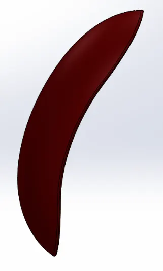
Rear Fender:
The rear fender is used to prevent sand, mud, rocks, liquids, and other roads spray from being thrown into the air by the rotating tire.
Feature used:
- Revolve
- Split
- Fillet
To design fender,
A curve shape of the fender is drawn on the Front plane sketch and it revolved about an axis up to 10 deg on the direction1 side and 141 deg on the direction 2 sides. To make the end of the fender sharper, sketch drawn on the Top plane, and using Split command the material is removed. Fillet command is used to make the edges smoother.
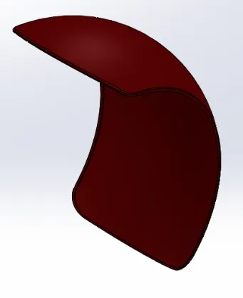
Kickstand:
Kickstand is used to hold a bike upright while you aren't riding it.
Feature used:
- Loft
- Dome
- Extruded cut
- Split
- Fillet
To design a kickstand,
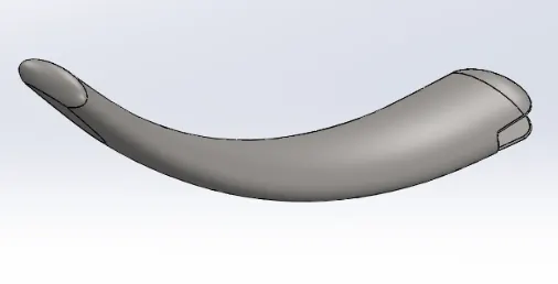
Two different sketches were drawn on two different planes. One sketch is the profile of the stand (i.e oval-like structure) drawn on the front plane, another sketch is the path line drawn on the right plane (through this path that oval structured profile travels up to the end of the path line). Loft feature is used to make the 3D profile of these 2 2Dsketches. A rectangular cutout is created on one end using Extruded cut feature. A circular pin is created between that rectangular cutout area using Extruded boss. The pin is used to connect the stand to the chassis and also makes to rotate the stand up to a certain degree. Fillet command is used to make the edges smoother.
Chain:
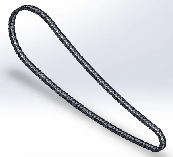
Chain is used to transmit the power from transmission box to the rear wheel. Chain consists of three parts, 2- chain links, pin. Outside chain link is in slightly differ from inside chain-link. Both chain links are connected by pin.
Feature used:
- Extruded Boss
- Curve Driven pattern
- Fillet
- Mirror
Chainlink-1, Chainlink-2
Chainlink1 and chain-link 2 were modeled and saved as blocks because the chain links are used repetitively so that they are saved as blocks instead of drawing each time.
To design chain,
A chain transmission path sketch is drawn on the front plane. Outside chain-link, inside chain-link, pins were drawn on the front plane and extruded using Extruded boss. After that Curve driven pattern is used to replica the chain links and pins. The transmission path is curved at the end side so a single curved driven pattern is not possible to make all the chain links because chain links were misaligned at the curved path. So that curve-driven pattern is allowed until one line starting and ending point. The curve is starting after the straight line then the chain links are again drawn on the sketch and extruded again Curve driven pattern up to the curve path ending point. The same process continues afterward.
Oil tank:
Feature used:
- Extruded Boss
- Combine
- Fillet
To design oil tank,
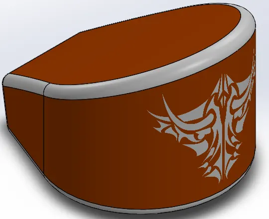
The outer body sketch is drawn on the top plane and extruded up to a certain 180mm using Extruded boss. To remove the unwanted material from the body, another sketch was drawn on the front plane and then extruded. Now both of them merged one over another and some portions of those parts were not merged. The required part is that merged one. To get that portion Combine feature is used inside that common check box to be selected.
Pedal:
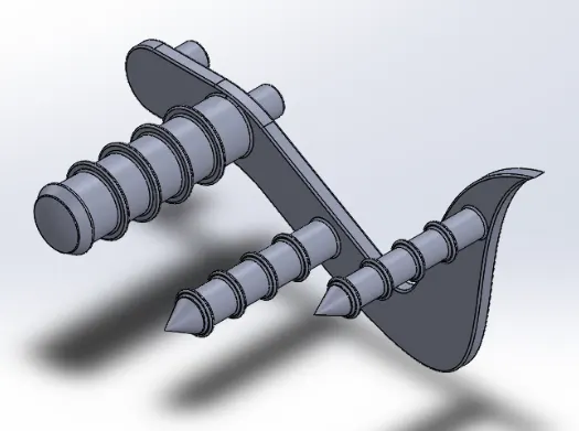
A pedal is used for resting the legs.
Feature used:
- Extruded Boss
- Fillet/Chamfer
To design the pedal,
A support plate sketch of the pedal is drawn on the front plane and extruded using Extruded boss. After that, the circular pin was made on one side to mount the pedal to the chassis. On another side of the supporting plate, different circular sketches were made for resting the foot.
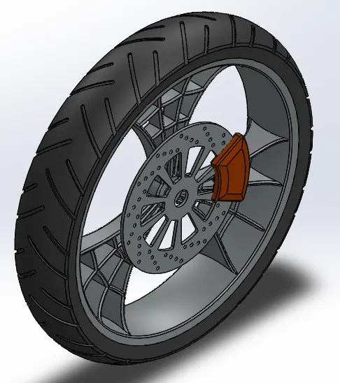
Front wheel:
Wheel is used to move the vehicle. Wheel consist of Rim, Tire.
Feature used:
- Revolved Boss
- Extruded Boss
- Extruded Cut
- Fillet/Chamfer
To design wheel,
Initially, the rim is designed by using Revolved boss. The outer Curved part of the rim is drawn on the front plane and then revolved 360 deg. After that inside support plates are drawn and extruded. To make a spider web design on the rim, excess materials were removed using extruded cut and a spider web sketch is drawn between the supporting plates of the rim and extruded.
Brake disc:
After designing the rim, a brake disc is created on one end of the rim. A circular sketch was drawn on the rim center face and extruded. Circular and rectangular sketches were drawn on the brake disc face to reduce the weight of the disc plate.
Brake caliper:
A brake caliper is modeled on a brake disc by drawing a sketch on the face of the brake disc and extruded. To remove the sharp corners, chamfer and fillets are used.
Tire:
After creating the caliper, the tire of the wheel is to be created. The tire sketch is drawn on the front plane and revolved 360 deg. To make the tire treads, treads sketches drawn on the front plane and using offset option the sketch off setted up to some distance and using offset from surface option to make a cutout on the tire surface.
Rear-wheel:
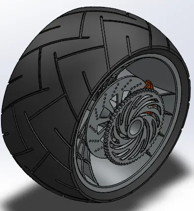
The wheel is used to move the vehicle. The wheel consists of Rim, Tire. Rear-wheel is larger in width when compared to rear wheel in this model.
Feature used:
- Revolved Boss
- Extruded Boss
- Extruded Cut
- Fillet/Chamfer
To design the wheel,
Initially, the rim is designed by using Revolved boss. The outer Curved part of the rim is drawn on the front plane and then revolved 360 deg. After that inside support plates are drawn and extruded. To make a spider web design on the rim, excess materials were removed using extruded cut and a spider web sketch is drawn between the supporting plates of the rim and extruded.
Brake disc:
After designing the rim, a brake disc is created on one end of the rim. A circular sketch was drawn on the rim center face and extruded. Circular and rectangular sketches were drawn on the brake disc face to reduce the weight of the disc plate.
Brake caliper:
A brake caliper is modeled on a brake disc by drawing a sketch on the face of the brake disc and extruded. To remove the sharp corners, chamfer and fillets are used.
Sprocket:
For the rear wheel, there is a sprocket is attached which is used to mount the chain.
The sprocket is attached at the end of the wheel rim. Sprocket outer diameter circle is drawn on rim’s center face and extruded. For gear tooth profile, teeth profile drawn on sprocket face and removed using extruded cut. Using the circular pattern option, the gear profile is created throughout the sprocket.
Tire:
After creating the caliper, the tire of the wheel is to be created. The tire sketch is drawn on the front plane and revolved 360 deg. To make the tire treads, treads sketches drawn on the front plane and using offset option the sketch off set up to some distance and using offset from surface option to make a cutout on the tire surface.
Chassis:
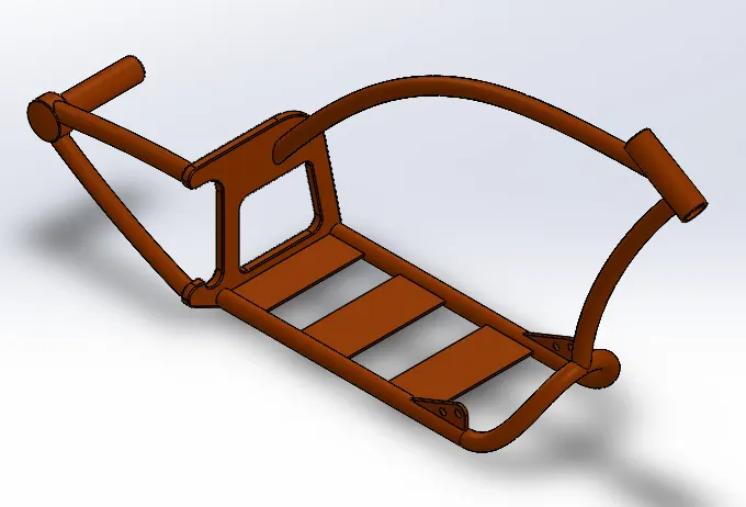
The chassis is the skeleton of the bike which is used to bear the weight of the bike in its idle and dynamic states. Engine, Forks, rear-wheel, and other components are mounted on the chassis.
Feature used:
- Swept boss
- Projection curve
- Extruded Cut
- Fillet/Chamfer
- Mirror
To design chassis,
The blueprint of the chopper bike is used to design the chassis. The 2d image is imported on Solidworks using Tools Sketch tools àSketch picture option. The chassis part is symmetry about the midplane so one side of the chassis is modeled and mirrored about the midplane.
The chassis frame is not a straight-line profile. It is inclined from all x,y, and z directions so a projection curve is used to create the 3d curve. A projection curve is created by drawing two different sketches on two different planes. The intersection between the two sketches is converted as a projected curve.
Gas tank:
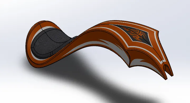
A gas tank is used to store the fuel.
options used:
- Surface Loft
- Surface extrude
- Swept surface
- Projection curve
- Surface knit
- Fillet/Chamfer
- Mirror
The gas tank profile is not a linear structure. It curves inwards and outwards so a projection curve is used to get the gas tank profile.
Engine:
Engine is the heart of the bike which produces energy through the combustion process. Linear motion of piston converted into rotational motion which is transferred to transmission box by a belt drive and then is transmitted to the rear wheel through a chain drive.
Feature used:
- Extruded Boss
- Swept boss
- Projection curve
- Extruded Cut
- Fillet/Chamfer
- Mirror
The engine block profile is drawn on a plane and extruded. For the Inclined V-engine setup, the swept feature is used. The path is drawn on one plane and the profile drawn on another plane to get the inclined profile.
Starter motor:
For the initial starting of the engine, a starter motor is needed. The starter motor which is connected to the flywheel, while starting it rotates the flywheel. The flywheel moves the piston up and down and ignition starts.
The starter motor is designed at the front end of the Engine block.
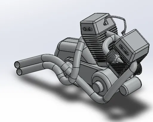
Exhaust manifold:
After combustion, the gas is released in form of smoke. They exit from the engine through the exhaust manifold. Projection curves are used to project the 3d curves of the exhaust manifold and different 3d projected curves are combined into single curve using Composite curve option
Assembly:
Open the Assembly window and open all the part files. In assembly window tab it shows all the pre-opened part files listed on the left side. Pick the part from the list and click on the assembly window. It automatically fixes the initial component. Chassis is the initial component fixed in the assembly window. All other parts are assembled with reference to the chassis axis system because while moving the chassis all other components also move. So that all components are assembled with reference to chassis.
Design modification:
After assembly, if any part is interfered with by other parts try to change the dimension of the part without affecting its functionality. In this assembly, the rear side of the chassis interfered with the exhaust manifold. so a rectangular cut-out is taken on chassis. Another interference is the exhaust manifold with the engine block. so the exhaust manifold inclination angle is changed.
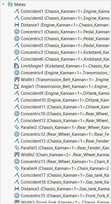
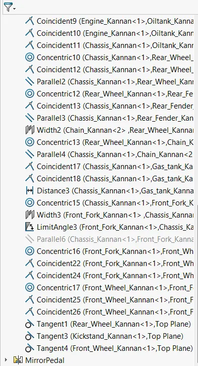
The engine is placed on the chassis using coincident and offset constraints. The kickstand is connected to the chassis using concentric and coincident constraints and it has rotational movement up to some degree because the stand is not always fixed in the same position while riding the stand is to be lifted up. so limit angle constraint is used.
Pedal connected to chassis using concentric and coincident constraints.
The transmission belt is connected to the engine using concentric and angle constraints.
Rear fork connected using concentric with wheel and coincident with front plane of chassis.
Front fork connected to the chassis using Concentric, Width coincident.
Front and rear wheels connected to chassis using concentric and face coincident constraints.
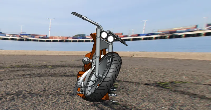
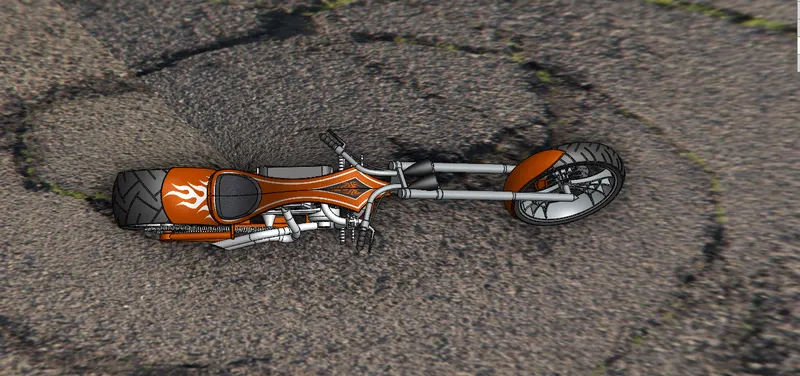
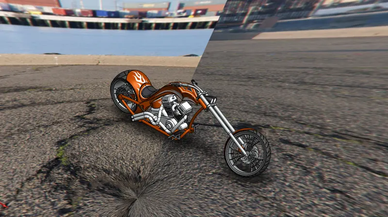
Rendering image:
Applying decals:
Click Tools-->Add-Ins-->Photoview 360 checkbox to be selected.
Render Tools tab displays on the solid works window.
To apply sticker effects to the model, click on Edit decals option in the Render tool tab. Apply the stickers available from the decal list available. Click on the face of part model to project the stickers.
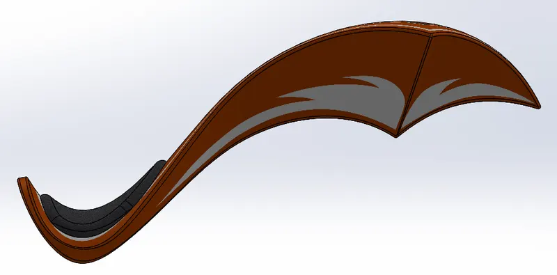
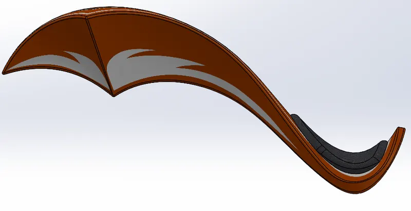
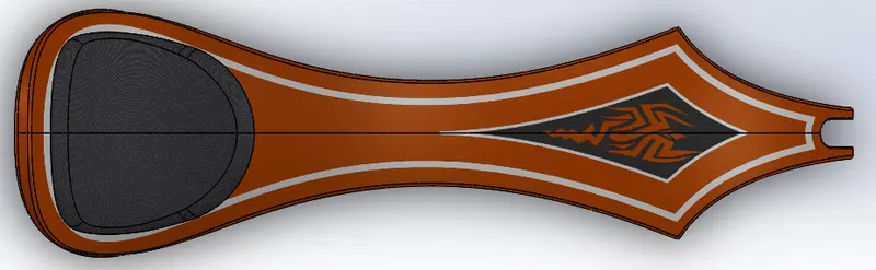
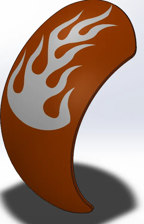
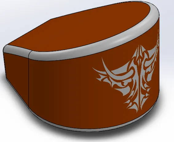
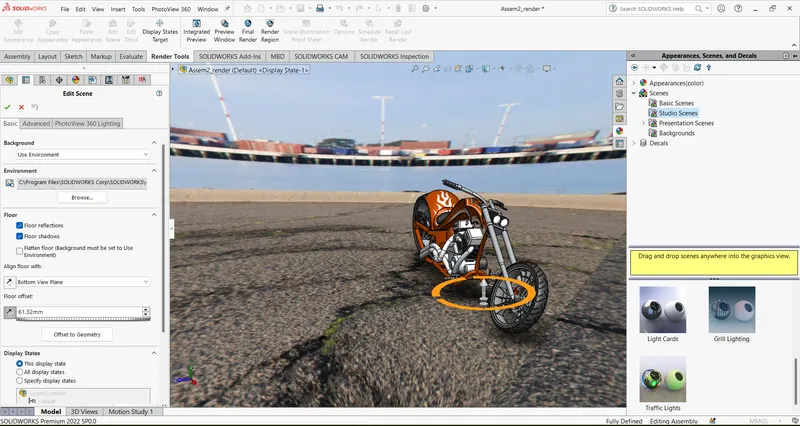
To set effects to the image, click on Edit scenes option in the Render tool tab. Apply the scenes from the list available. I chose Grill lightning effect and Urban background effect.
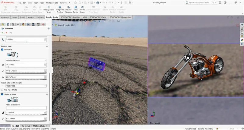
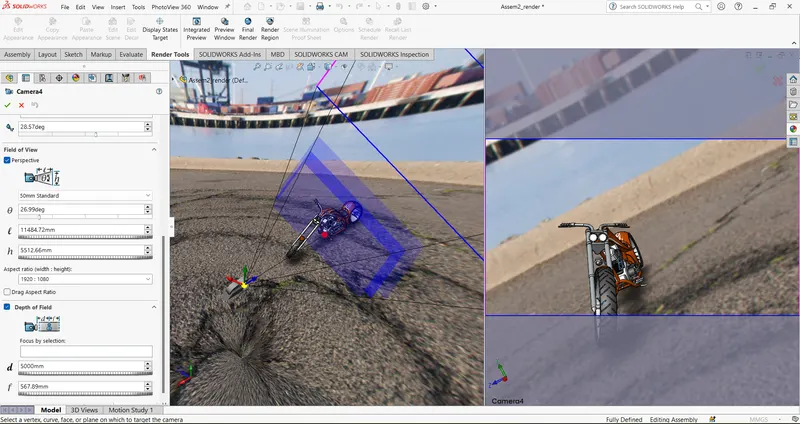
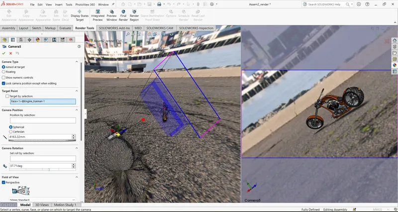
To create a camera view:
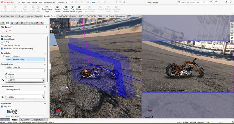
Click on View-->Light and camera--> Add camera option to create a new camera view.
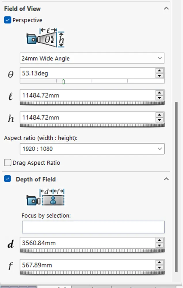
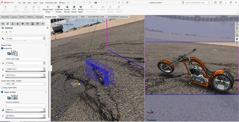
Use the Field of view option to move the camera views and change the values in Depth of field as per requirements.
After creating the camera view, use Preview window option to preview the rendered image. If the quality is not good, keep changing the values in the camera and add additional lights for a clarity view.
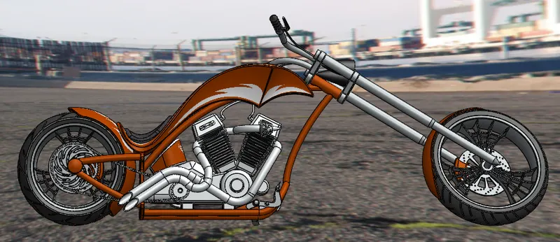
Rendered images:
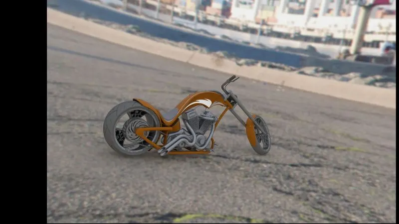
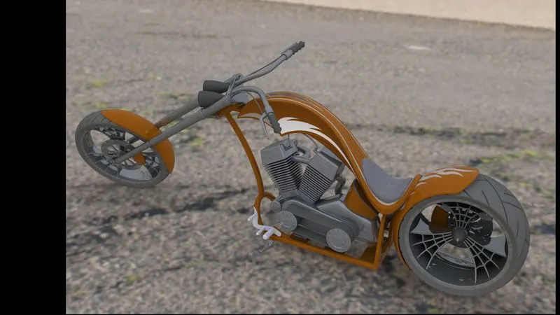
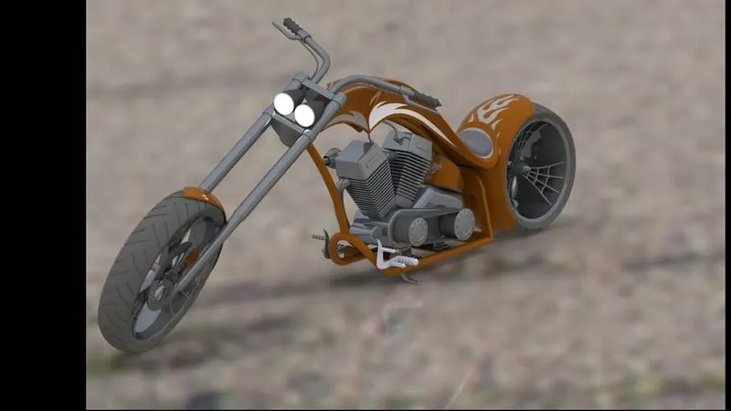
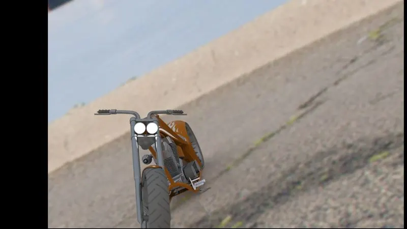
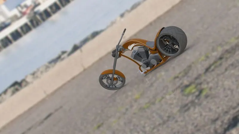
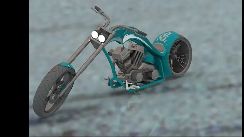
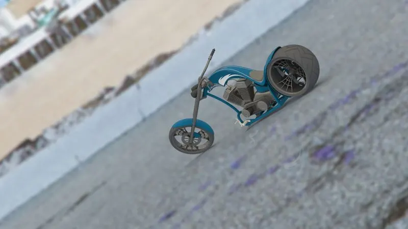
colour changed after rendering of camera 3 & 5 images
Conclusion:
The American chopper model is designed and assembled. and also the decals were added to the bike successfully.