Photo Realistic Rendering
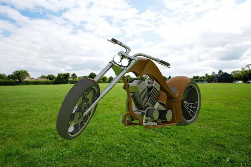
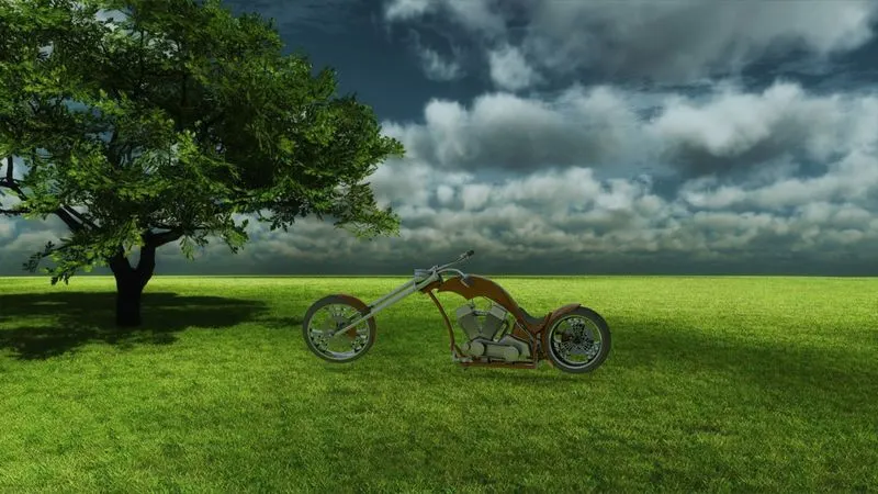
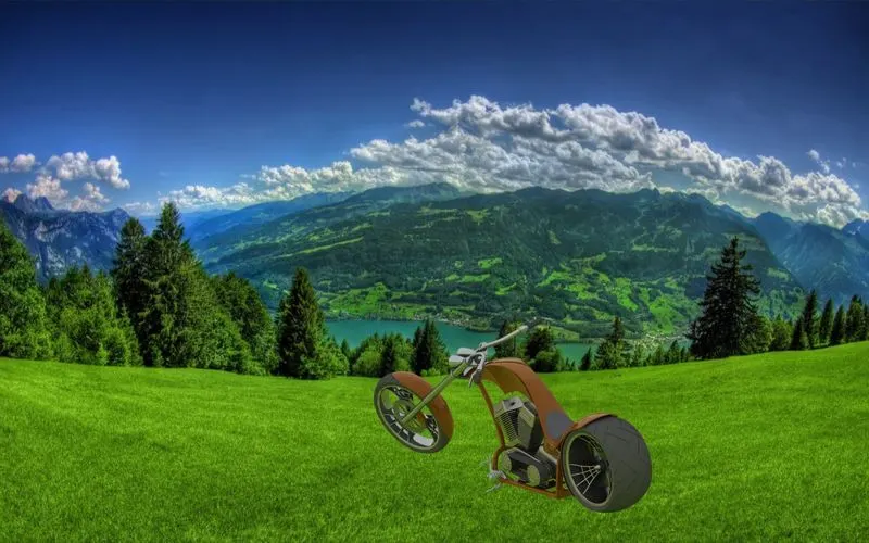
AIM: Photo Realistic Rendering of an american chopper motorcycle.
OBJECTIVES:
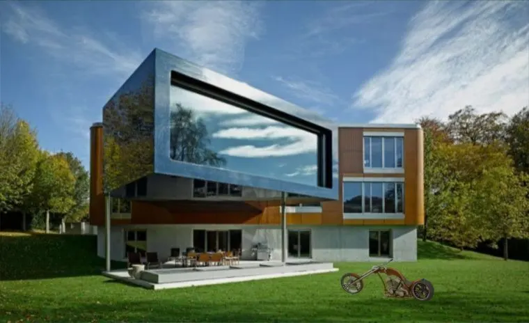
Objective of this project is to Create a photo-realistic Conceptual model of an American Chopper using solid works.By creating part drawings, converting them to 3D models, assembling the created parts and finally giving it a photorealistic view by rendering the model using Photoview-360.
INTRODUCTION:
- CHOPPER:A chopper is a type of custom motorcycle which emerged in California in the late 1950s. The chopper is perhaps the most extreme of all custom styles, often using radically modified steering angles and lengthened forks for a stretched-out appearance. They can be built from an original motorcycle which is modified (chopped) or built from scratch. Some of the characteristic features of choppers are long front ends with extended forks often coupled with an increased rake angle, hardtail frames (frames without rear suspension), very tall 'ape hanger" or very short "drag" handlebars, lengthened or stretched frames, and larger than stock front wheels
- SOLIDWORKS:
The SOLIDWORKS is a mechanical design automation application that lets designers quickly sketch out ideas. experiment with features and dimensions, and produce models and detailed drawings.
Photo-View 360 is a SOLIDWORKS add-in that produces photo-realistic renderings of SOLIDWORKS models. The rendered image incorporates the appearances, lighting, scene, and decals included with the model.
SOLIDWORKS Visualize is a photo-realistic rendering tool that utilizes our CAD data to create magazine quality images or commercial quality animations.
DESIGN METHODOLOGY:
DESCRIPTION:
(Tools/ Features used while designing),
- Creating 2-D Sketches:
A 2D sketch is the base to create a 3D model. It is usually created on the X-axis & Y-axis. This includes lines, circles, rectangles, splines, etc.
- Geometric Relation:
Geometric relations are one of the most powerful features in SOLIDWORKS. They're used in the sketch level to control the behaviors of the sketch entities when they are moved or rotated and to keep the associations between one another.
- Solid Extrude:
It extrudes a sketch or selected sketch contours in one or two directions to create a solid feature.
- Extude Cut:
Extrude cut is a feature which helps to remove materials from the 3D model. It is just opposite to extrude boss/base feature, because it cuts a sketch profile while extruding. It can cut in both directions and mainly used for creating holes, channels, slots etc.
- Revolve Boss:
Revolves a sketch or selected sketch contours around an axis to create a solid feature.
- Revolve Cut:
Cuts a solid model by revolving a solid mdel around an axis.
- Swept Boss:
This feature sweeps a closed profile along an open or closed path to create a solid feature.
- Loft:
The loft feature creates a shape by making transitions between multiple profiles and guides curves thus allowing to create complex geometry with a single tool. This feature can be used in both solid as well as surface modelling.
- Dome:
a rounded vault forming the roof of a building or structure, typically with a circular base.
- Linear Pattern:
Use linear patterns to create multiple instances of one or more features that you can space uniformly along one or two linear paths.
- Circular pattern:
Use circular patterns to create multiple instances of one or more features that you can space uniformly around an axis.
- Fillet:
Fillet/Round creates a rounded internal or external face on the part. You can fillet all edges of a face.
- Chamfer:
it is used to connect two adjacent faces using an inclined line.
- Trim:
The trim command is used to remove or erase the extra edges of intersecting lines on a 2D sketch. You can use Power trim to trim multiple, adjacent sketch entities by dragging the pointer across each sketch entity.
- Offset:
Adds sketch entities by offsetting faces, edges, curves, or sketch entities to a specified distance.
- Split:
Use the Split feature to create multiple parts from an existing part. You can create separate part files, and form an assembly from the new parts.
- Solid Merge:
It combines mutiple body to create one body.
- Projected Curve:
You can project a sketched curve onto a model face to create a 3D curve. You can also create a 3D curve that represents the intersection of two extruded surfaces generated by creating sketches on two intersecting planes.
- Convert Entities:
You can create one or more curves in a sketch by projecting an edge, loop, face, curve, or external sketch contour, set of edges, or set of sketch curves onto the sketch plane.
- Shell:
The shell tool hollows out a part, leaves open the faces you select, and creates thin-walled features on the remaining faces. If you do not select any face on the model, you can shell a solid part, creating a closed, hollow model. You can also shell a model using multiple thicknesses.
- Mirrior:
This allows to mirrior features, faces and bodies allong a faces or plane.
- Surface Knit:
combines two or more adjacent, non-intersecting surfaces together.
COMPONENTS:
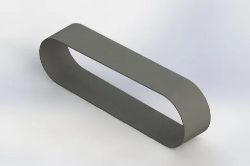
1.BELT:
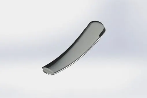
2. KickStand:
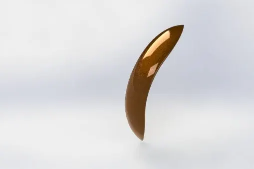
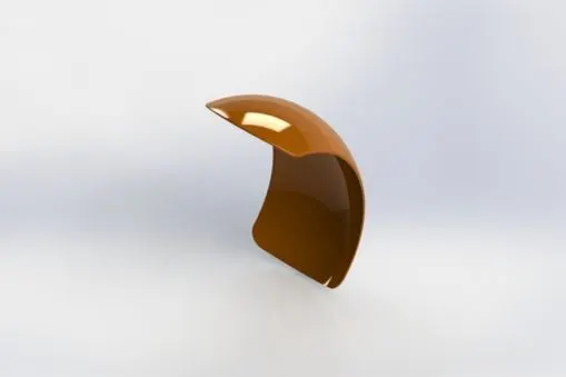
3. FrontFender
4. Rear Fender:
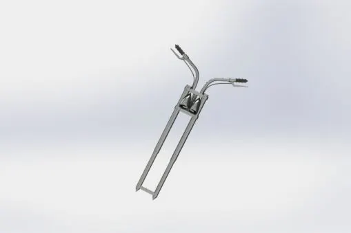
5. FrontFork:
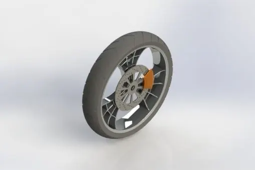
6. Front Wheel:
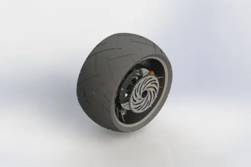
7. Rear Wheel:
8. Pedal:
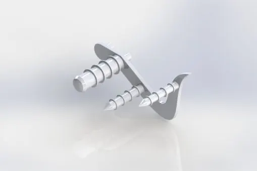
9. Oil Tank:
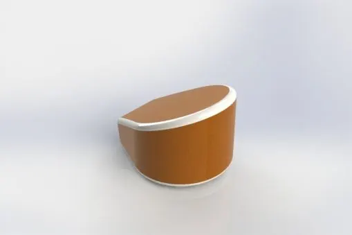
10. Gas Tank:
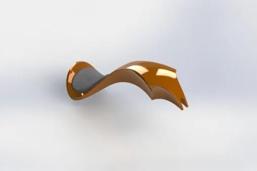
11. Engine:
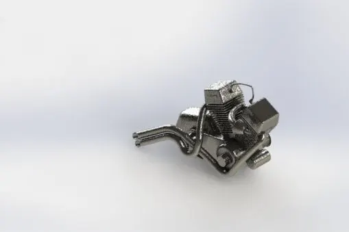
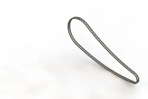
12. Chain:
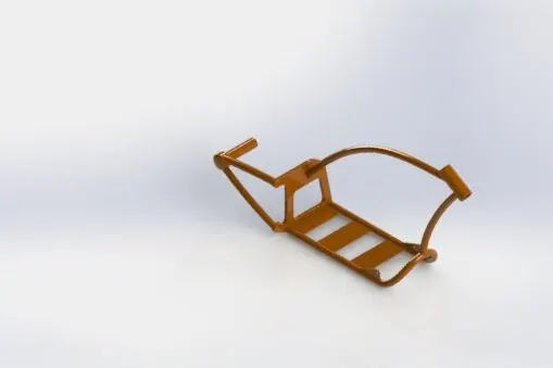
13. Chassis:
ASSEMBLY:
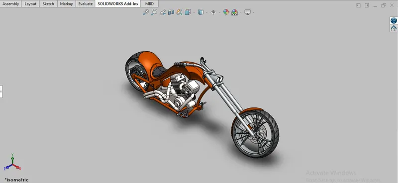
1. Isometric View.
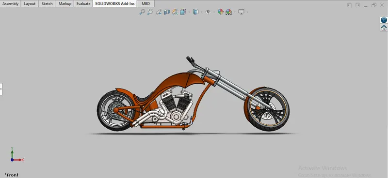
2. Front View.
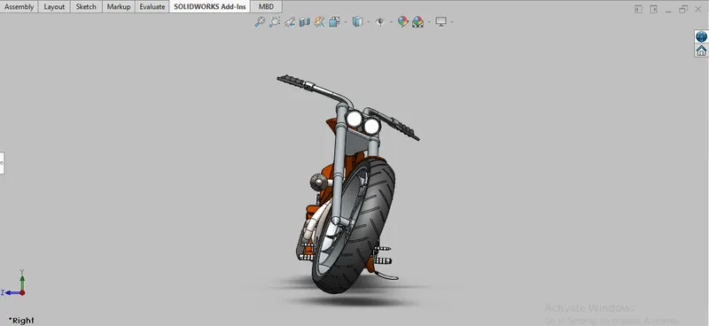
3. Right Hand View:
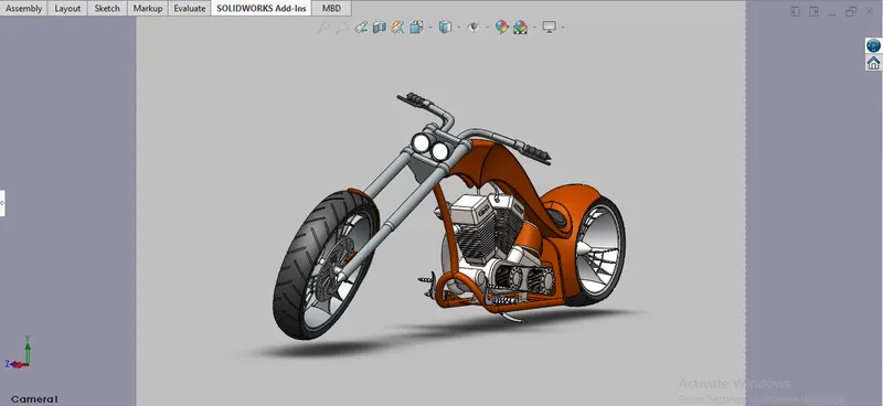
4. Camera View:
RENDERED IMAGE: