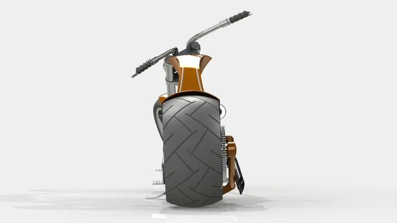
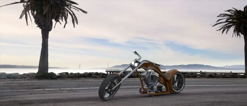
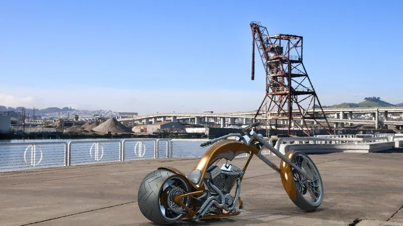
Photo Realistic Rendering
PHOTO REALISTIC RENDERING
OBJECTIVE:
- To model individual part of the American chopper with proper dimensioning and relevant features in Solidworks.
- To assemble all the parts using appropriate mates.
- Rendering final assembly to get photorealistic model using solidworks photoview 360 or solidworks visualise.
INTRODUCTION:
- Solidworks is a 3D CAD and CAE software developed by Dassault Systémes. It provides dedicated tools and workflows that streamline the design and development of products. It is used for sketching, part modelling, sheet metal design, simulation, mold design, and other computer-aided manufacturing processes.
- Solidworks Visualize is a standalone computer application majorly employed to create photorealistic or non-photorealistic renders. It is also used for post-processing images and even creating basic presentation animations.
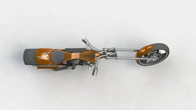
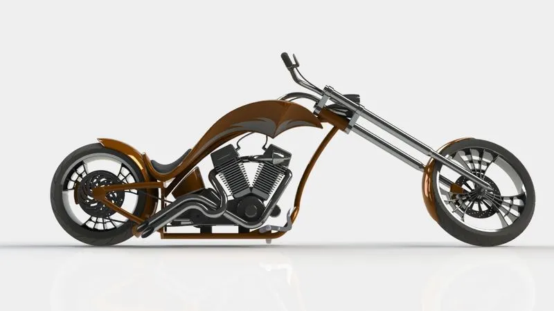
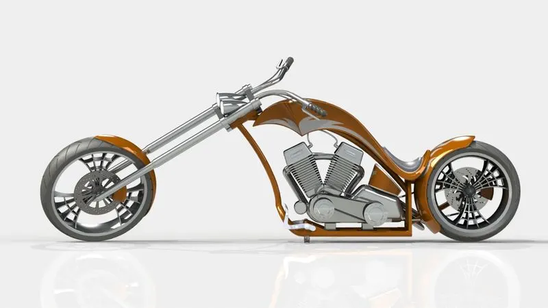
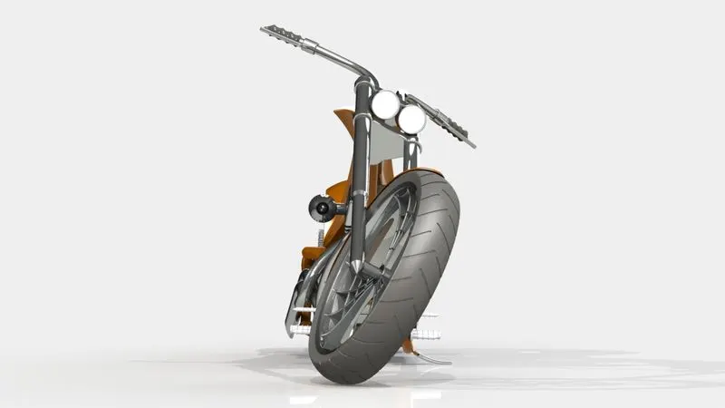
- American Chopper is a concept of a motorcycle, based on the television series of the same name, built by Orange County Choppers. It is a cruiser motorcycle in which the riding position is usually with the feet forward and the hands up, with an erect spine or slight lean towards the back, to provide easy rideability and gear-shifting for the rider.
DESIGN METHODOLOGY:
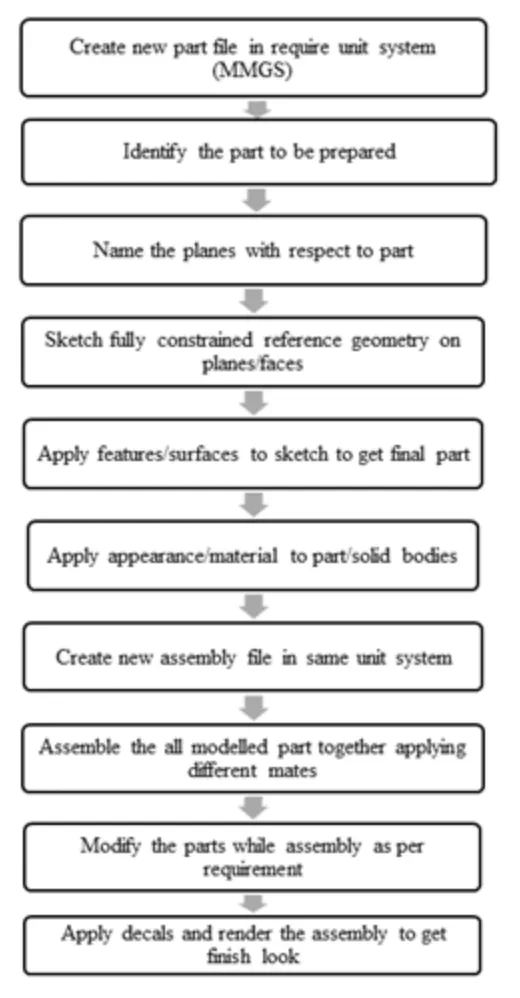
- The Bottom-up Approach is implemented to design the American Chopper. In this approach the parts are modelled individually in their respective part files and then assembled by importing them into a common assembly file. It is usually employed for off-the-shelf or existing components which can be assembled based on their specifications. This also helps with the manufacture of individual components and to easily make different configurations for different specifications.
DESCRIPTION:
The American Chopper model constitutes the following parts:
- Transmission Belt
- Kickstand
- Front Fender
- Rear Fender
- Chain
- Pedal
- Oil Tank
- Front-wheel
- Rear-Wheel
- Front Fork
- Engine
- Chassis
- Gas Tank
The parts are modelled individually in designated part files and saved in a dedicated folder.
1. Transmission Belt:
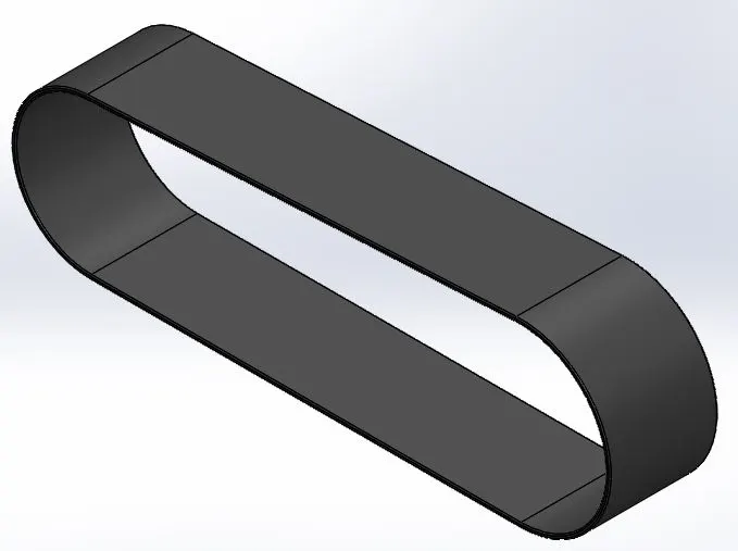
The Transmission Belt is used for transmitting motion from the engine to the driving shaft/sprocket of the gearbox. Its design is one of the easiest in the assembly and employs basic sketch tools like circle, line, trim, offset, and features like extrude and fillet as discussed below:
- Sketch
- Circle
- Line
- Trim
- Offset
- Smart Dimension
- Extruded-Boss/Base
- Fillet
Sketch: It is a two-dimensional representation of the body in a plane. It needs to be completely defined with proper geometric relations and dimensions.
Circle: This tool is used to create a circle with a defined center and a diameter.
Line: This tool is used to create a straight line with a defined position and length.
Trim: This tool is used to remove sketch entities with respect to certain references.
Offset: It is used to copy the sketch entities with the same shape and proportional dimension at a distance.
Smart Dimension: It is used to provide proper dimensions to a sketch feature and automatically provides the relevant dimension for a particular selection.
Extruded Boss/Base: It creates a solid body by giving thickness to the selected sketch contours.
Fillet: It creates a circular feature to the selected edges or faces in a solid body. This is often used to round off sharp edges in a model.
2. Kickstand:
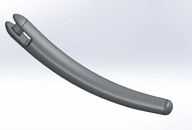
Kickstand also known as sidestand, gives support to the American Chopper during rest. It is one of the smallest components in the assembly. Its design employs new sketch tools such as ellipse, spline, and features like Extruded-cut, Loft, Split and Dome as follows:
- Sketch
- Ellipse
- Spline
- Circle
- Smart Dimension
- Lofted Boss/Base
- Dome
- Extruded Cut
- Split
- Extruded Boss/Base
- Fillet
Ellipse: It is used to create an ellipse with a defined focal length and radius of curvature.
Spline: It is used to create a curve with defined endpoints. The curvature can be altered by enabling the curve handlers which can be given a defined direction and strength.
Lofted Boss/Base: It is used to create a solid body with the help of at least two sketches as the transition faces and at least one sketch as a guide curve.
Dome: It is used to create a curvature about an end face.
Extruded Cut: It removes material from a solid body with the help of sketched contours.
Split: It is used to split a solid body into individual parts with the help of a Trim tool. The split bodies can be either kept or removed using the Consume Cut part option.
3. Front Fender:
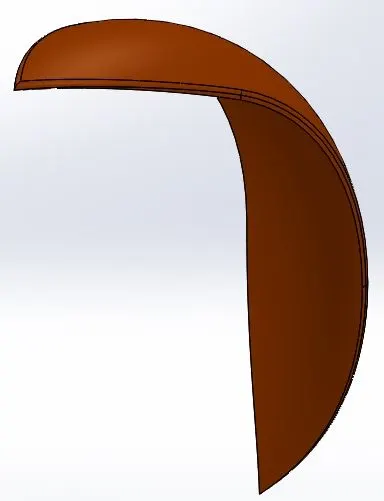
Front fender gives support to the front wheel and acts as a medium of safety for the rider as well as the engine block. Its design employs new features like Revolved Boss/Base as follows:
- Sketch
- Circle
- Centerline
- Trim
- Offset
- Smart Dimension
- Revolved Boss/Base
- Spline
- Split
- Fillet
Centerline: This tool is used to create a straight line for construction with a defined position and length.
Trim: This tool is used to remove sketch entities with respect to certain references.
Revolved Boss/Base: It creates a solid body by giving thickness to the selected sketch contours about an axis of revolution.
4. Rear Fender:
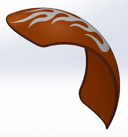
Rear fender gives support to the rear wheel and acts as a medium of safety for the rider. The rear fender employs further features like Shell in the design process as follows:
- Sketch
- Circle
- Centerline
- Trim
- Offset
- Smart Dimension
- Revolved Boss/Base
- Spline
- Split
- Fillet
- Shell
Shell: It creates a hollow feature from a solid body with a specified thickness.
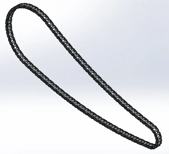
5. Chain:
Chain transmits the motion from the gearbox to the rear wheel sprocket. Its design uses new sketch tools like make block, insert block and features like Curve pattern and Mirror as follows:
- Sketch
- Circle
- Centerline
- Spline
- Trim
- Offset
- Block
- Extruded Boss/Base
- Fillet
- Curve-driven Pattern
- Mirror
Block: This feature creates a set of entities as a collective set to be able to import into the file.
Curve-driven Pattern: It is used to duplicate features or bodies along a sketched curve with defined distance and number of instances.
6. Pedal:
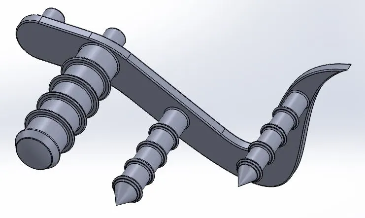
Pedal is used for shifting gears and also for brakes. Its design utilises new features like Chamfer and Linear pattern as follows:
- Sketch
- Circle
- Centerline
- Spline
- Offset
- Trim
- Smart Dimension
- Revolved Boss/Base
- Dome
- Fillet
- Chamfer
- Linear Pattern
Chamfer: It is used to remove and flatten sharp edges on a solid body.
Linear Pattern: It creates duplicates of a feature or a body in a specified linear direction.
7. Oil Tank:
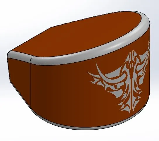
Oil tank is used to store the engine oil, which is fed to the engine. Its design uses new sketch tool three point arc and feature Combine in the design process as follows:
- Sketch
- Three point arc
- Centerline
- Spline
- Trim
- Smart Dimension
- Extruded Boss/Base
- Fillet
- Shell
- Combine
Three point arc: This tool is used to create an arc with three defined points(two endpoints and a center point) and a defined radius.
Combine: It merges two or more different bodies into a single solid body.
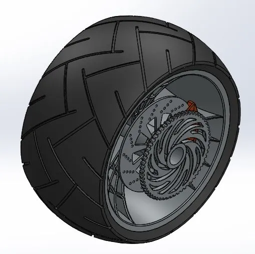
8. Front Wheel:
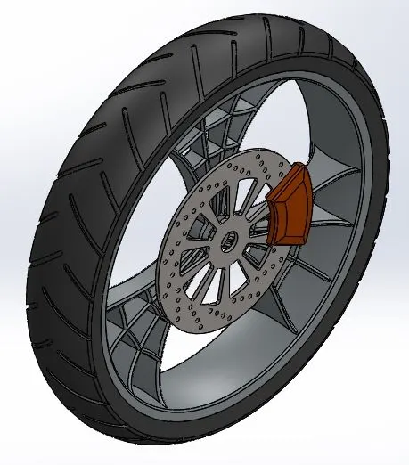
Front Wheel is a free wheel which is mounted to the Front fork. Its design employs new sketch tools like center-point rectangle and features like Revolved cut, Circular pattern as follows:
- Sketch
- Circle
- Centerline
- Spline
- Trim
- Center-point Rectangle
- Revolved Boss/Base
- Extruded Cut
- Revolved Cut
- Extruded Boss/Base
- Fillet
- Chamfer
- Circular Pattern
Center-point Rectangle: It is used to create a rectangle with its center defined first and then its length and breadth dimensioned.
Revolved Cut: It removes material from a solid body with the help of sketched contours about an axis of revolution.
Circular Pattern: It is used to duplicate features or bodies about a specified point or axis with defined distance and number of instances.
9. Rear Wheel:
Rear Wheel transmits motion from the sprocket to the ground, thereby resulting in translation of the entire Bike. Its design employs similar features as in front wheel as listed below:
- Sketch
- Circle
- Centerline
- Spline
- Trim
- Center-point Rectangle
- Revolved Boss/Base
- Extruded Cut
- Revolved Cut
- Extruded Boss/Base
- Fillet
- Chamfer
- Circular Pattern
10. Front fork:
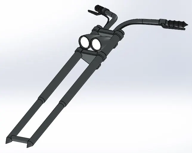
Front Fork holds the headlights, handle and front fender and acts as a joint between the front wheel and the chassis. Its design utilizes new features like Project Curve, Swept Boss/Base, and Reference geometry as follows:
- Sketch
- Circle
- Line
- Centerline
- Spline
- Trim
- Revolved Boss/Base
- Extruded Boss/Base
- Extruded Cut
- Revolved Cut
- Fillet
- Project Curve
- Swept Boss/Base
- Linear Pattern
- Dome
- Combine
- Reference Geometry
Reference Geometry: It creates reference entities such as a point or an axis or a plane or even a coordinate system.
Project Curve: It creates a 3D curve that represents the intersection of the two extruded surfaces generated by creating sketches on two intersecting planes.
Swept Boss/Base: It creates a solid body by moving a profile along a defined path.
11. Chassis:
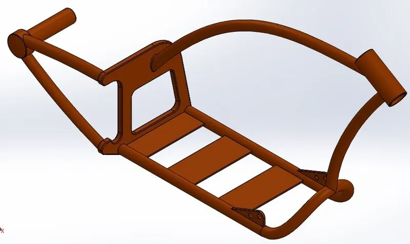
Chassis is the main structure of the Assembly which holds all the components together. The strength of the assembly relies solely on the chassis. Its design employs new sketch tools like Sketch picture as follows:
- Sketch
- Circle
- Centerline
- Rectangle
- Spline
- Trim.
- Revolved Boss/Base
- Extruded Boss/Base
- Extruded Cut
- Revolved Cut
- Fillet
- Chamfer
- Circular Pattern
- Linear Pattern
- Dome
- Combine
- Reference Geometry
- Sketch Picture
Sketch Picture: It inserts an image file on a selected plan to be used as a reference to model complex entities.
12. Engine:
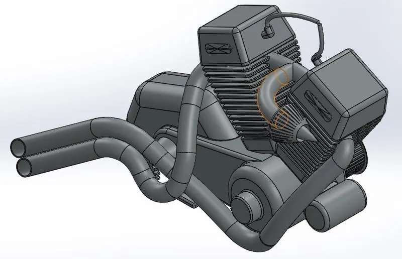
Engine is the power source for the Chopper. Its design employs new features like Composite curve as follows:
- Sketch
- Circle
- Centerline
- Rectangle
- Spline
- Trim.
- Revolved Boss/Base
- Extruded Boss/Base
- Extruded Cut
- Revolved Cut
- Fillet
- Chamfer
- Circular Pattern
- Linear Pattern
- Dome
- Combine
- Reference Geometry
- Sketch Picture
- Composite Curve
Composite Curve: It creates a 3D curve by combining two or more different curves lying on different planes.
13. Gas Tank:
Gas Tank stores the fuel and also holds the seat for the rider. The design involves the usage of new features like Split line and Surface tools as follows:
- Sketch
- Centerline
- Spline
- Trim
- Swept Surface
- Trim Surface
- Lofted Surface
- Boundary Surface
- Mirror
- Knit Surface
- Fillet
- Split Line
- Circular Pattern
- Linear Pattern
- Dome
- Combine
- Reference Geometry
- Sketch Picture
- Project Curve
Swept Surface: It creates a closed profile along a defined path to create a surface feature.
Trim Surface: It removes the selected surface about an intersection.
Lofted Surface: It creates a surface which transitions between two or more profiles or sketches.
Boundary Surface: It creates a surface between tangent profiles/surfaces.
Knit Surface: It combines two or more adjacent and non intersecting surfaces into a single surface body.
Split line: It projects entities on to surfaces or curved faces and divides the targeted features.
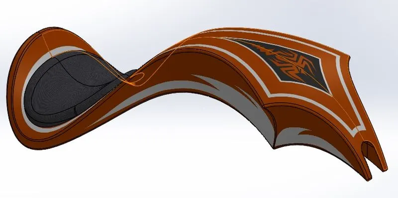
ASSEMBLY OF AMERICAN CHOPPER:
The components are assembled together by importing them into the assembly file and applying mates to them in an orderly manner. The different mates used during the assembly of american chopper are as follows:
- Coincident Mate
- Concentric Mate
- Limit Angle Mate
- Width Mate
- Parallel Mate
- Distance Mate
OUTPUT VIEW:
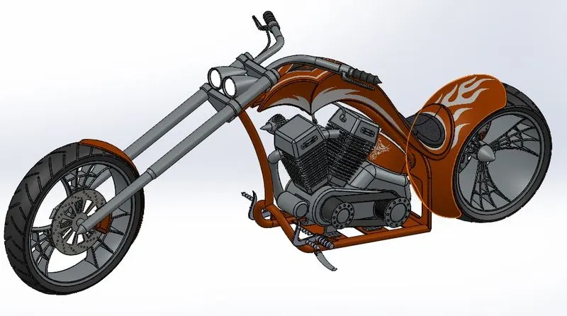
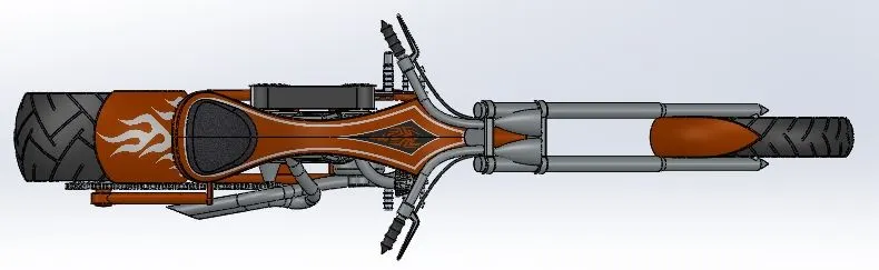
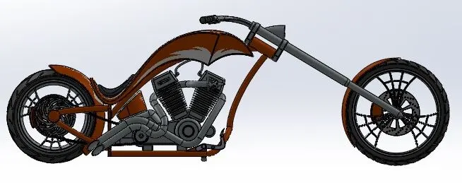
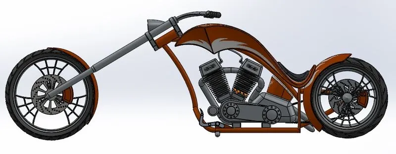
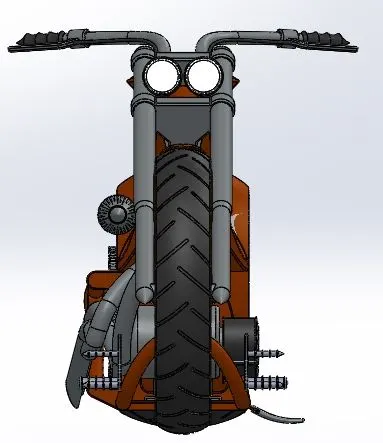
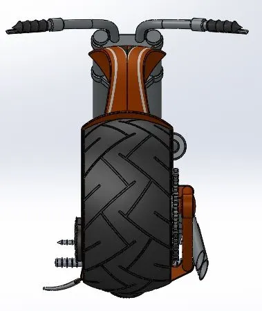
PHOTO REALISTIC RENDERING:
- Rendering is the process of creating realistic image model in real world environment.
- Rendering can be done two ways in solidworks.
- Photoview 360
- Solidworks Visualize
RENDERED IMAGES IN PHOTOVIEW 360: