Photo Realistic Rendering
ASSEMBLY AND RENDERING OF AMERICAN CHOPPER
1. OBJECTIVE
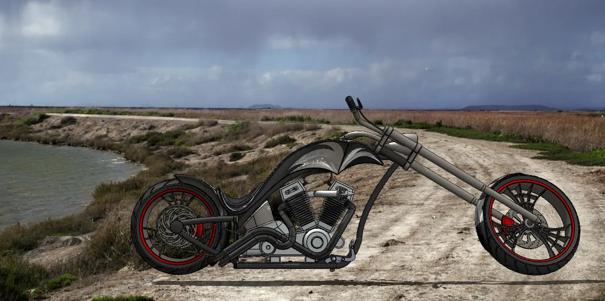
To use SolidWorks to make a 3D model of the American Chopper. Using SolidWorks, create models of the various chopper subassemblies. To create the finished model, assemble the component parts. To obtain a photorealistic model, render the finished model.
2. INTRODUCITON
Bikes classified as American Choppers have long wheelbases, extended front suspension travel, low seat heights, low ground clearance, high rake angles, and trails. The majority often feature webbed rims, a very curved exhaust pipe, a larger front tire with a wider diameter, a retro headlamp, and an upright upper torso with a small lean toward the back. The position of the foot pegs requires the rider to extend their legs forward. Handlebars are typically broad and high. Because of the limited ground clearance and increased risk of scratching foot pegs, floor boards, or other components if turns are made at the speeds that other motorcycles can complete more easily, comfort is prioritized over cornering abilities.
3. DESIGN METHODOLOGY
The process of creating a part begins with completely realized 2D designs. These drawings serve as references for various features that were used to design the 3D portion. Sketch has a number of choices for generating different types of entities.
- Line, Circle, Spline, Polygon, Fillet, Offset, Convert, and Trim entities are some examples.
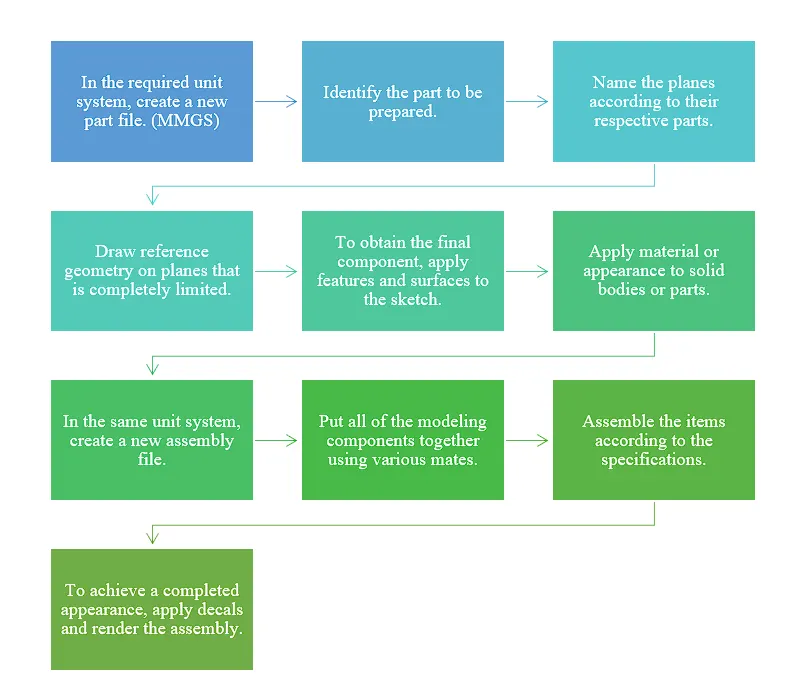
Several ways to use the choices above,
- Features and Surfaces - These tabs provide several options that can be used to build solid bodies and surfaces in various shapes.
- Appearance - This capability allows us to give a part or model a material or visual look. These appearances aid in our rendering process to provide a realistic image.
4. DESCRIPTION
The descriptions of the sub-assembly design process are provided below.
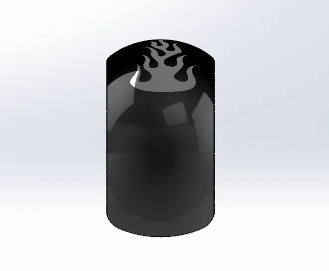
1. Oil Tank
- A tank that can accommodate the amount of oil needed to keep the motorcycle cool.
- Based on the dimensions provided in the upper plane, a 2D sketch is produced.
- After that, the drawing is extruded 170 mm in one direction and 10 mm in the other.
- On the front (mid-plane), a fresh sketch is made, and it is extruded into both directions utilizing every available option.
- Using the combine function, two models are combined to create a shared portion.
- To guarantee that the shell is applied, the edges are filled with pellets, and a 3mm thick shell feature is applied. This is previewed using a section that has been sliced.
- The oil tank's appearance is altered to a required colour with white edges.
- Part is saved.
Utilized Features
- Extrude boss - This feature is used to convert 2d sketch into 3d object.
- Shell - This feature hollows out part, leaves open the faces selected and creates thin walled feature on remaining faces. Also, it creates closed hollow model.
- Fillet - This feature is used to convert external and internal edges into rounded shape.
- Combine - It allows combining two or more solid bodies.
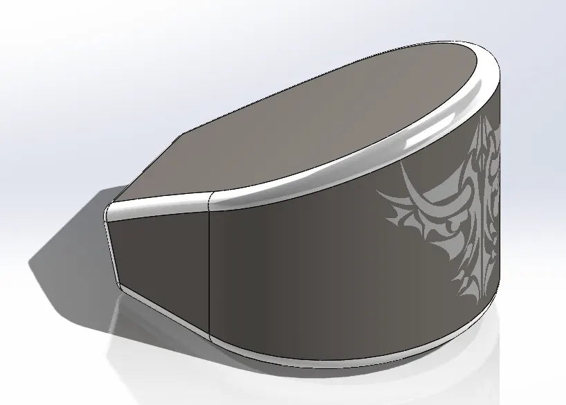
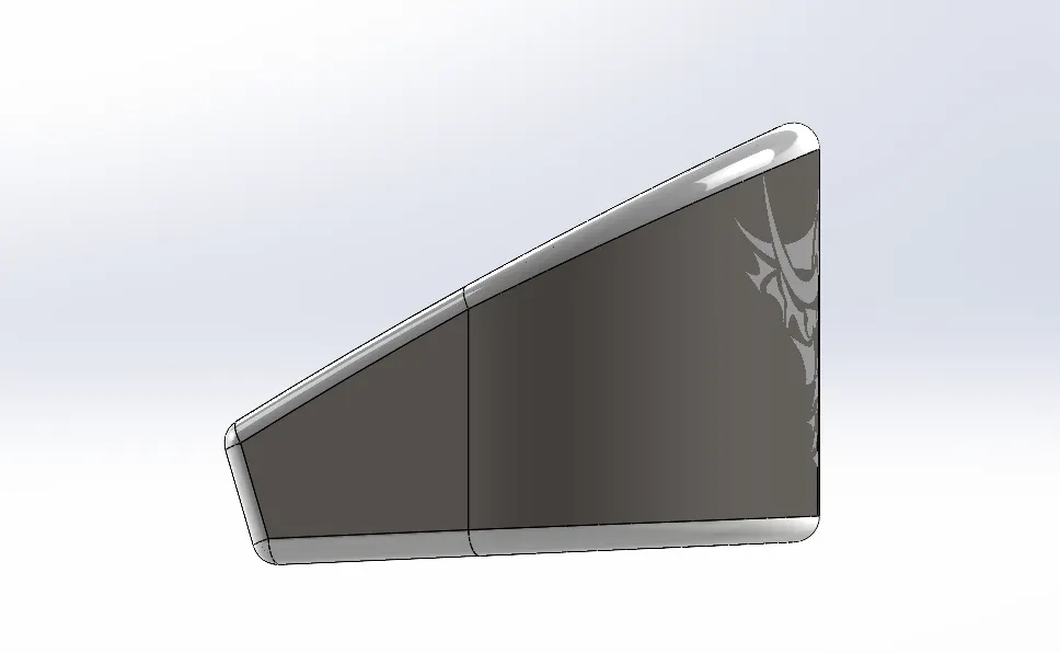
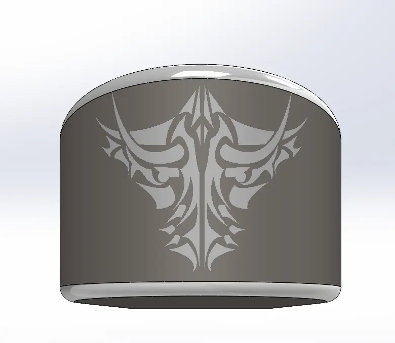
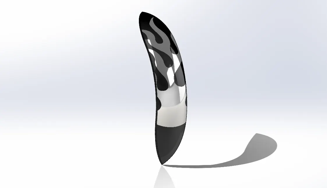
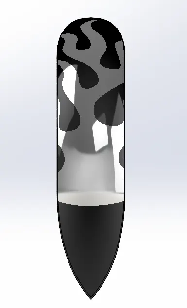
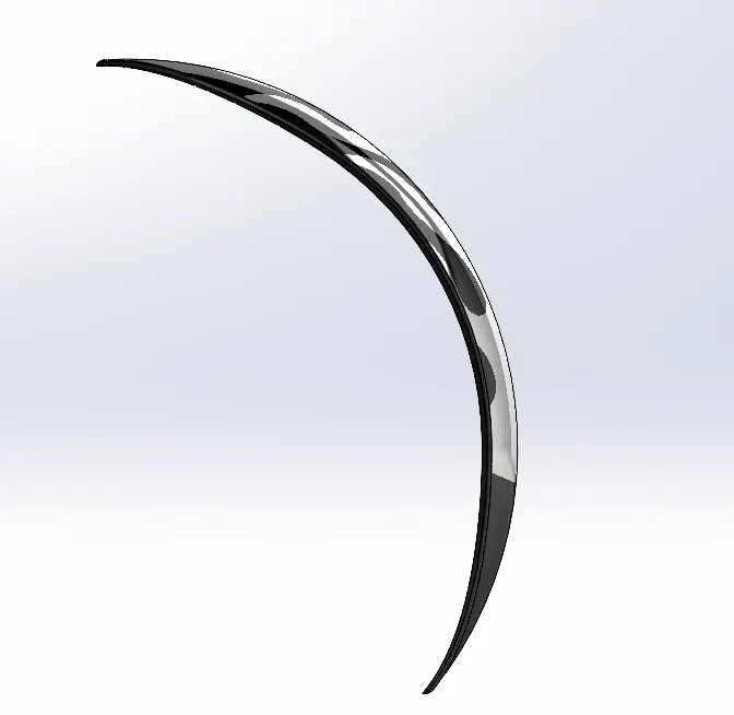
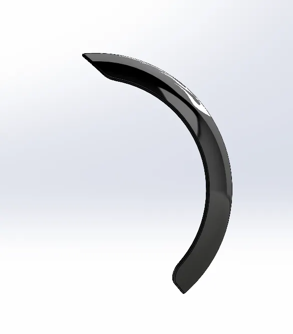
2. Front Fender
- It is positioned beneath the front fork and on the front wheel. It stops dirt particles from being propelled skyward by turning tires.
- Drawing - In a vertical plane, a three-point arc is drawn above the origin, and the same arc is shifted six millimetres inward. Utilizing extend and trim entities, the sketch is closed. In order to rotate the sketch, a construction line is drawn at the origin in the vertical plane of the necessary dimensions.
- Relationships & Dimensions - The arc's width is 160 mm, its radius is 125 mm, and its centre is located 280mm above the origin.
- Characteristics - Using the revolve extruded boss/bass command, the entire sketch is rotated around the axis for 5 degrees in direction 1 and 130 degrees in direction 2. Using the drawing, a portion of the body is eliminated using the split command at the top end of the body to generate the necessary geometry shape in the centre plane using spline and line commands with dynamic mirror on. The same process is used in the vertical plane to remove the body portion that needs to be shaped to the appropriate shape at the bottom of the body. Every border on the upper part of the body has a 6 mm fillet.
Features Used
- Revolve - Any profile can be revolved about an axis, centre line or edges and obtain solid bodies from 0 degrees to 360 deg.
- Dynamic mirror - In this you can mirror any sketch or entities about pre-selected sketch or entity.
- Offset entities - It is used to create same entities on some distance.
3. Rear Fender
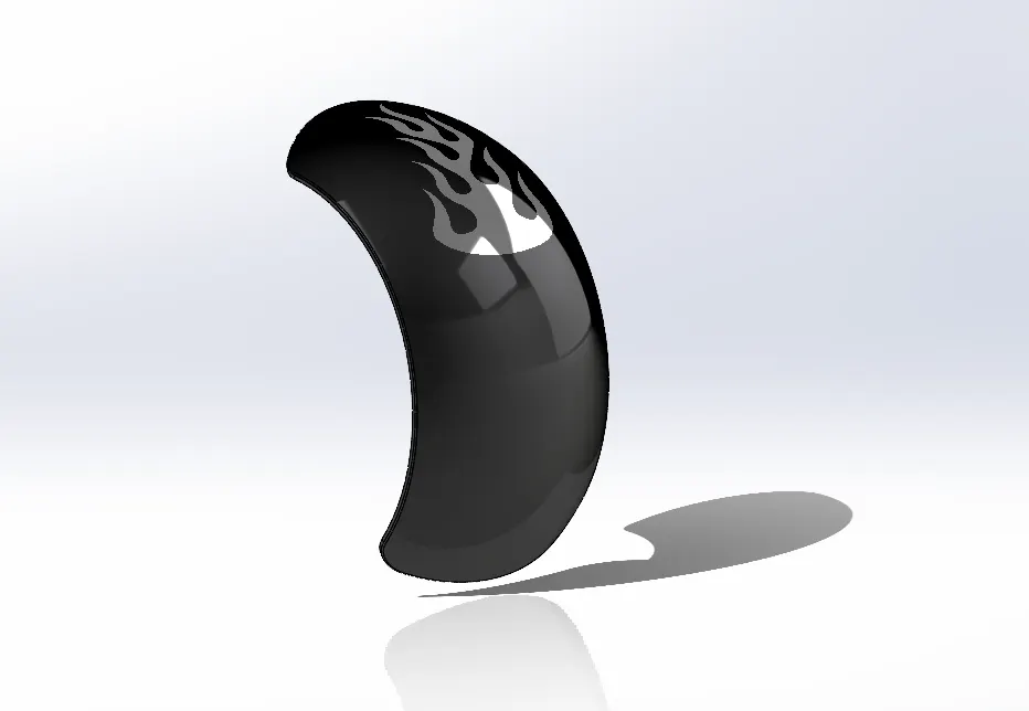
- Rear fenders are used in the same way as front fenders. It is situated atop the back wheel on a chassis.
- Drawing - In a vertical plane, a three-point arc is drawn above the origin, and the same arc is shifted six millimetres inward. Utilizing extend and trim entities, the sketch is closed. In order to rotate the sketch, a construction line is drawn at the origin in the vertical plane of the necessary dimensions.
- Relationships & Dimensions - The arc's width is 364 mm, its radius is 290 mm, and its centre is 90 mm above the origin.
- Characteristics - Using the revolve extruded boss/bass command, the entire sketch is rotated around the axis for 10 degrees in direction 1 and 140 degrees in direction 2. To cut off a portion of the body using a three-point arc, a desired shape is sketched on the centre plane. Then, using the sketch and the construction line, the desired portion of the body is removed using the split command. The fender's remaining sharp edges are filleted for a radius of 4 mm, while all four corner edges are filleted for a radius of 45 mm. The inner face of the fender is chosen, and the shell command is used to hollow it out by 4 mm.
Features Used
- Shell - This feature hollows out part, leaves open the faces selected and creates thin walled feature on remaining faces. Also, it creates closed hollow model.
- Revolve - Any profile can be revolved about an axis, centre line or edges and obtain solid bodies from 0 degrees to 360 deg.
- Split - This feature is use to split the solid bodies, surfaces and allow us to remove unnecessary portion.
- Fillet - This feature is used to convert external and internal edges into rounded shape.
4. Transmission Belt
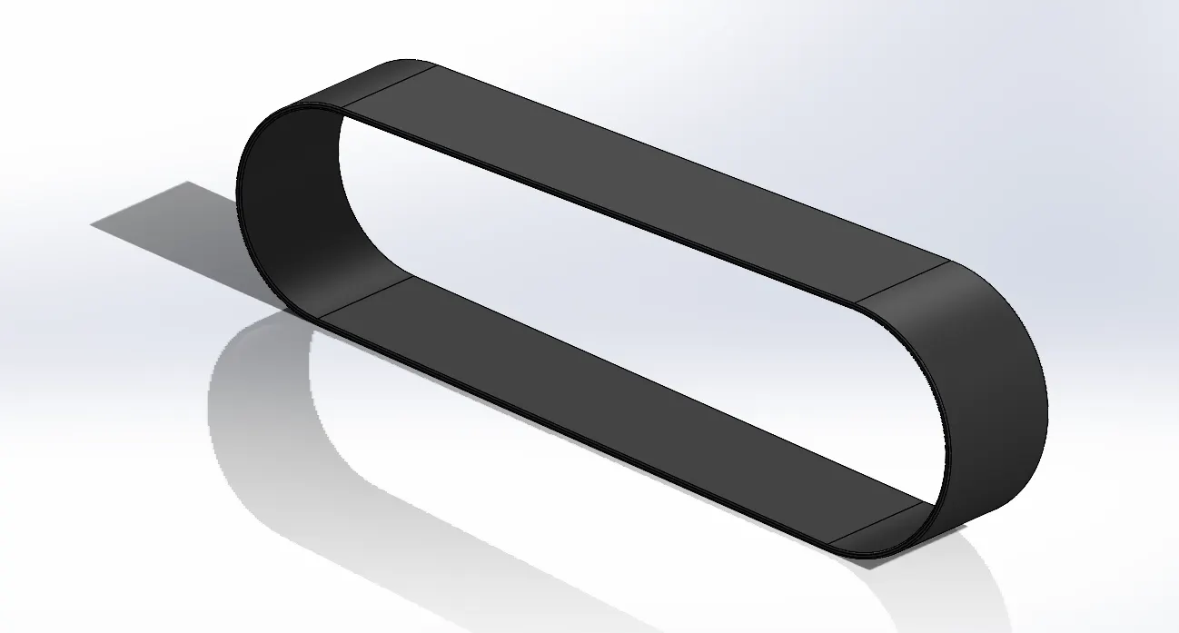
- It transfers engine power to the gearbox.
- Drawing - The transmission belt sketch is made up of lines and arcs. The original sketch is kept intact and the entire thing is offset for 3.5mm.
- Measurements & Relationships - The two arc's centres are 350 mm apart, with the larger arc's radius measuring 70 mm and the smaller arc's radius measuring 60 mm. Using the horizontal relation, a line starting at 350 mm is rendered horizontal, and the tangency relation maintains the tangency between the lines and the arcs.
- Characteristics - Using the Extruded Boss/bass command, the entire sketch is extruded to 88mm. Every edge on the component has a 1 mm fillet.
Features Used
- Extrude boss - This feature is used to convert 2d sketch into 3d object.
- Fillet - This feature is used to convert external and internal edges into rounded shape.
- Offset entities - It is used to create same entities on some distance.
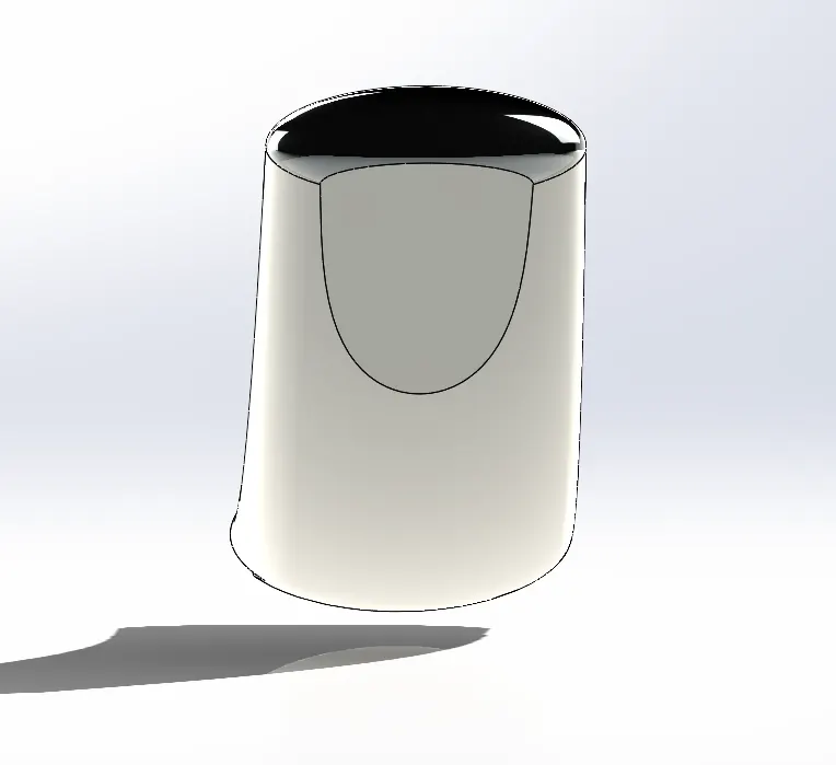
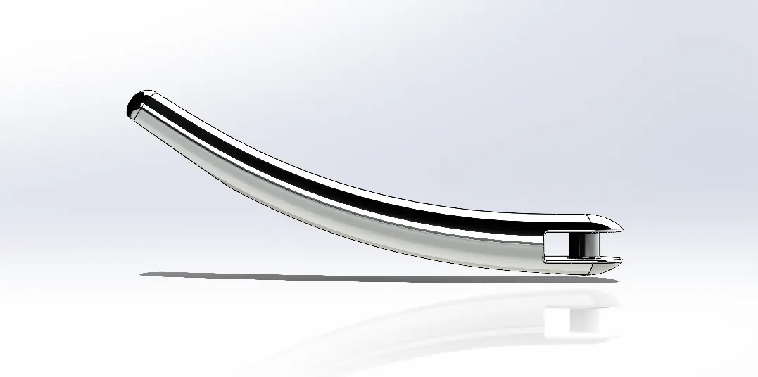
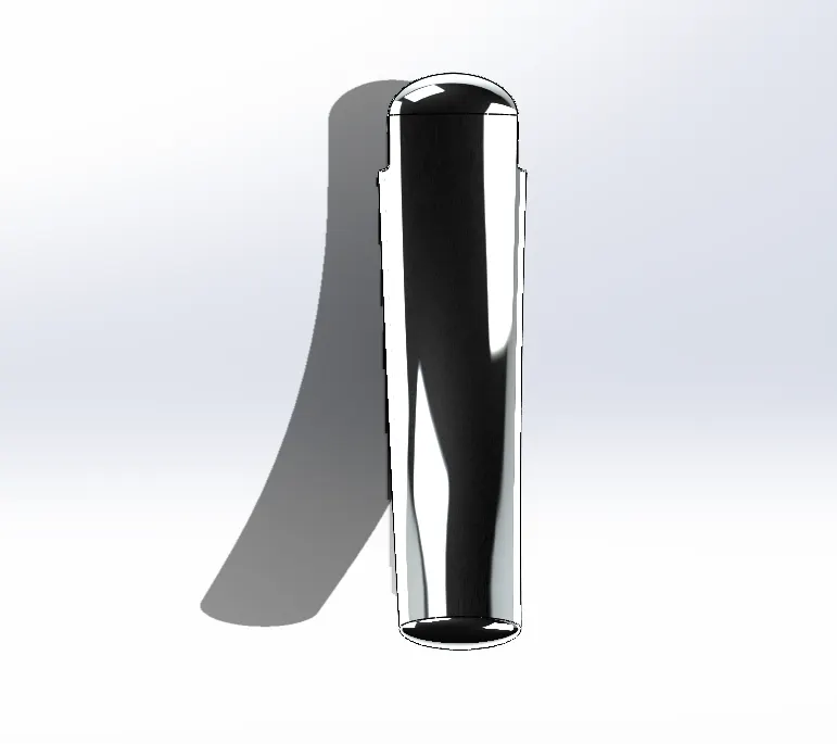
5. Kick Stand
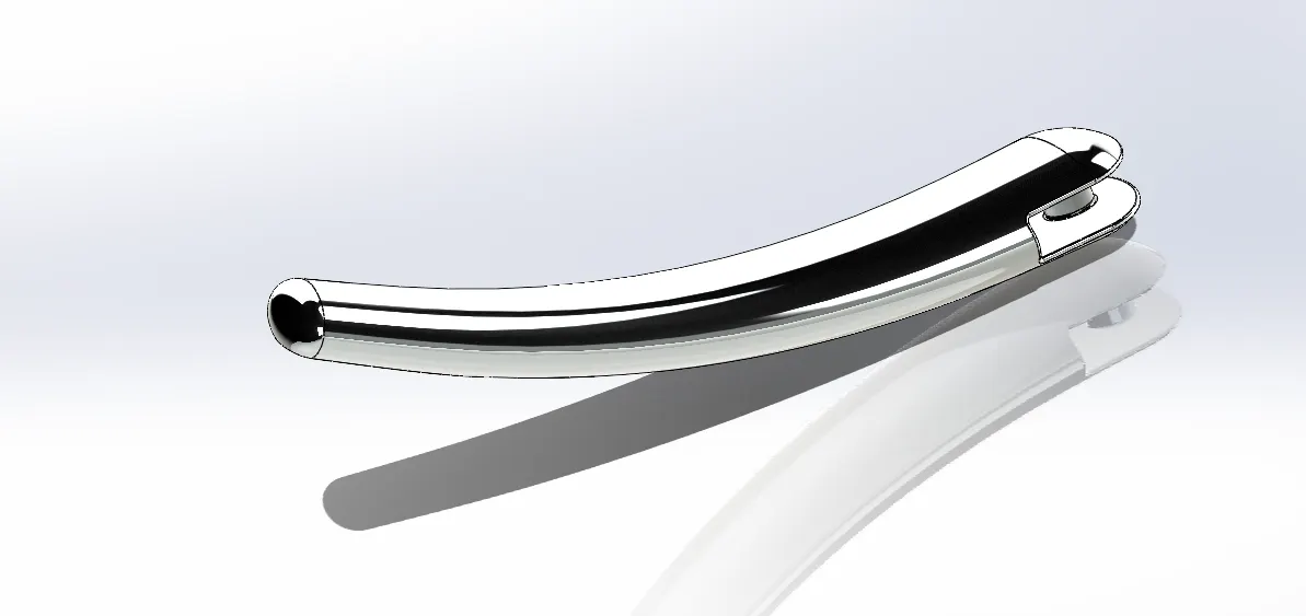
- When not in use, it is utilized to support the chopper and pivots to allow it to travel along the frame.
- Drawing - Drawings of an ellipse and a spline are made from the origin in the front and right planes, respectively. By selecting the Reference geometry option to create a new plane at the spline's end point, another ellipse is drawn there.
- Relationships & Dimensions - The larger ellipse has 40 mm of horizontal dimension, 18 mm of vertical dimension, and is constructed horizontally to the origin utilizing a dynamic relation. The spline end point is located 110 mm vertically and 202 mm horizontally from the origin. Dimensions of smaller ellipse at newly created plane is 40mm horizontally, 18mm vertically & is made horizontal to origin using dynamic relation.
- Features - By choosing the spline utilizing a lofted boss or base, a loft is formed by going from a larger to a smaller ellipse. At both ends, there is an oval dome with dimensions of 13 mm and 5 mm, respectively. By utilizing the "Split" cut body option, the material at the bottom of the kickstand is removed to create a flat face. Drawing an 8 by 28 mm rectangle and selecting "Extruded" through it all creates an extruded cut at the larger end. By building an extruded boss with a 9mm diameter, a pivot point is formed at the larger end to attach to the frame. Fillets have distinct borders measuring 2 mm and 0.5 mm, respectively.
Features Used
- Extrude boss - This feature is used to convert 2d sketch into 3d object.
- Fillet - This feature is used to convert external and internal edges into rounded shape.
- Loft - It determines the profiles used to create a loft. Select sketch profiles, faces or edges to connect. Lofts are created based on the order of profile selection.
- Dome - This is used to apply dome shape to faces. This allows you to apply domes to irregularly shaped contours.
- Split - This feature is use to split the solid bodies, surfaces and allow us to remove unnecessary portion.
- Extrude cut - It is used to add pockets, cut-outs, and other features to your current solid model.
6. Pedal
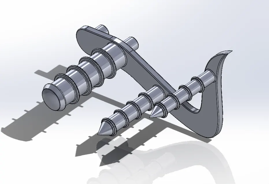
- It is attached to chassis to rest rider's foot while driving.
- A 2D drawing is made at the front plane using the specified dimensions, and it is extruded up to 8 mm using an extruded boss or base.
- On the model's front face, a fresh sketch is made and extruded up to 20 mm.
- Using the revolved boss/base feature, another sketch is made on the opposite side of the model.
- The revolving part's end face is equipped with a dome feature.
- Two other components had an asymmetrical chamfer added to them.
- Using the offset entities option at the base of the three components, a new drawing is made and extruded from the face at a 20 mm offset of 2.5mm.
- The newly formed extruded sections are given a linear pattern and filled with pellets, resulting in four identical examples spaced 20 mm apart.
- The model's remaining edges are given filters.
- Part is saved.
Features Used
- Linear pattern - This pattern is same like circular pattern. But it works like its name linearly along a line, centreline or edge at require instances.
- Revolve - Any profile can be revolved about an axis, centre line or edges and obtain solid bodies from 0 degrees to 360 deg.
- Extrude boss - This feature is used to convert 2d sketch into 3d object.
- Fillet - This feature is used to convert external and internal edges into rounded shape.
- Dome - This is used to apply dome shape to faces. This allows you to apply domes to irregularly shaped contours.
- Chamfer
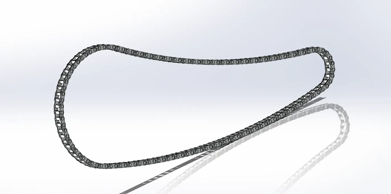
7. Chain
- It is part of transmission system. It helps to transmit power from engine to rear wheel with help of sprocket mounted on rear wheel and engine.
- Mirror and curve-driven pattern are the primary aspects.
- Following the renaming of the planes, a sketch is made at the mid-plane using the specified dimensions.
- In order to store each block as a distinct component and use it to generate the links, a runaway sketch is produced in the midplane and blocks are created, specifically as chain_link1 and chain_link2.
- In order to align the blocks with the curve, they are placed onto the 2D design made on the midplane and given specific relations.
- Following the extrusion of the blocks, fillets are added to the pin faces.
- In order to precisely align with the chain path, a curve-driven pattern is applied along the curve and some extrudes are manually created.
- Afterwards, in order to maintain organization, the solid bodies are divided into pins and chain plates and placed in different folders. The chain plates are then reflected using a mirror entity.
- The chain has Chrome Appearance added on it.
- Part is saved.
Features Used
- Curve Pattern - It allow to pattern solid bodies along a curve path at required instances.
- Block - Sometimes we need a single sketch multiple time. We can convert such a sketch into block at add it whenever require.
- Mirror - It helps to mirror half portion
- Extrude boss - This feature is used to convert 2d sketch into 3d object.
- Fillet - This feature is used to convert external and internal edges into rounded shape.
8. Front Wheel
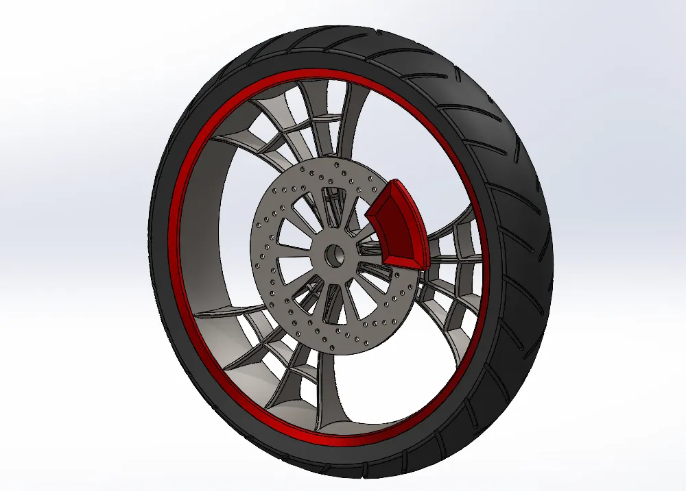
- A wheel is a circular block made of a strong, durable material, with a hole bored through the centre for a front axle bearing, which allows the wheel to rotate when torque or gravity apply force to it.
- The "outer edge of a wheel, holding the tire" is referred to as the rim. On vehicles like automobiles, it constitutes the outer circular design of the wheel where the inside edge of the tire is fastened.
- Brake Calliper: A brake that applies friction to a disk or "rotor" by pressing a set of pads against it is called a disc brake. A shaft, like an axle on a car, is slowed down in rotation by this action, which can either hold the shaft stationary or lower its rotational speed. Motion energy is transformed into waste heat that needs to be released.
Features Used
- Combine - It allows combining two or more solid bodies.
- Circular pattern - It is used to pattern the feature circular at require instances.
- Chamfer - It creates sloping surface at solid bodies corner or edges.
- Extrude boss - This feature is used to convert 2d sketch into 3d object.
- Extrude cut - It is used to add pockets, cut-outs, and other features to your current solid model.
- Revolve - Any profile can be revolved about an axis, centre line or edges and obtain solid bodies from 0 degrees to 360 deg.
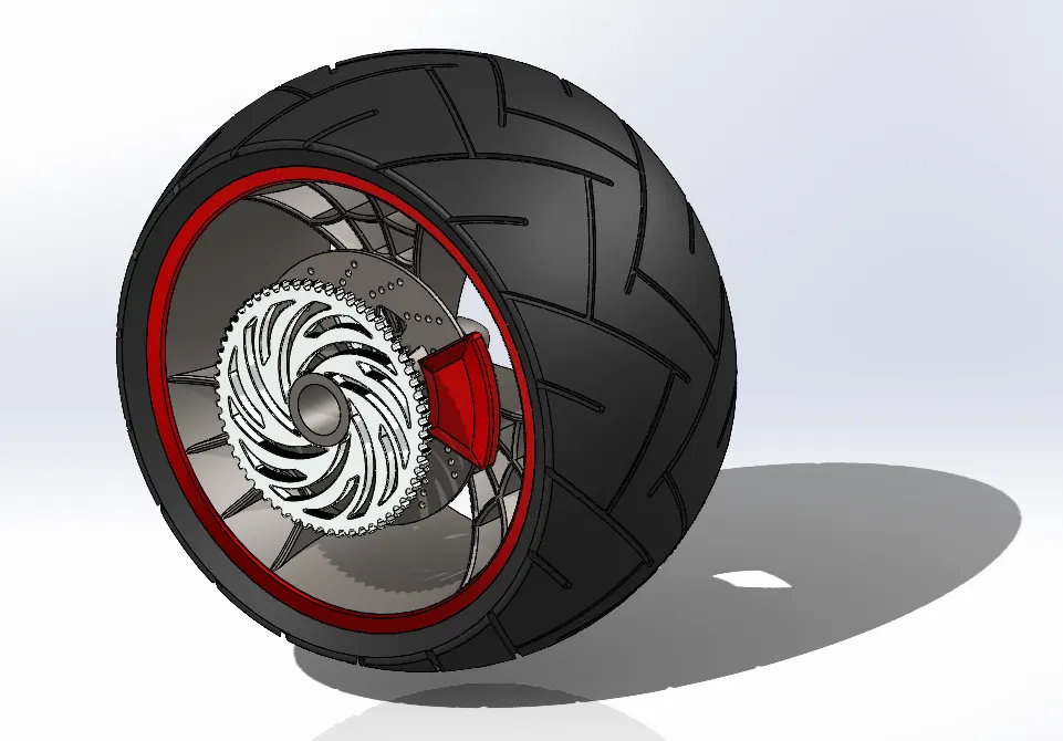
9. Rear Wheel
Features Used
- Combine - It allows combining two or more solid bodies.
- Circular pattern - It is used to pattern the feature circular at require instances.
- Chamfer - It creates sloping surface at solid bodies corner or edges.
- Extrude boss - This feature is used to convert 2d sketch into 3d object.
- Extrude cut - It is used to add pockets, cut-outs, and other features to your current solid model.
- Revolve - Any profile can be revolved about an axis, centre line or edges and obtain solid bodies from 0 degrees to 360 deg.
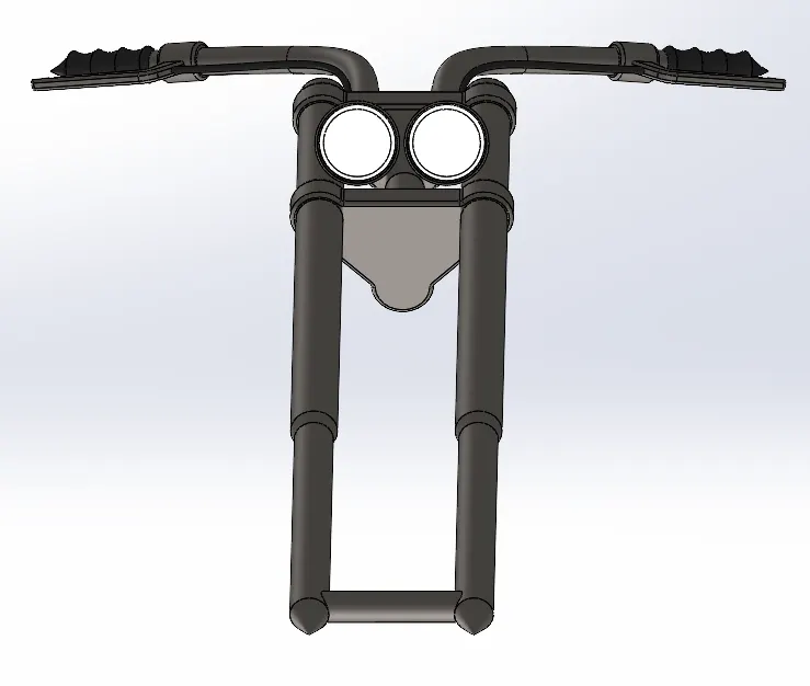
10. Front Fork
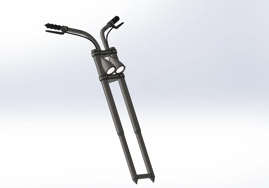
- It is the bike's handling system. It is attached to the front wheel and chassis.
- Motorbike wheels are designed to withstand both axial and radial forces. They also offer a means of attaching additional crucial parts, like the suspension, final drive, and brakes. Everything that is directly attached to a wheel is regarded as unsprung mass.
- The front fork lessens bouncing when driving on uneven terrain and keeps too much weight off the front wheel during abrupt breaks. The front fork's grip with the road surface allows it to maintain appropriate damping.
Features Used
- Project curve - It helps to get 3d curve which is projected on the basis of two 2d sketches.
- Sweep - This feature creates solid body from 2d sketch profile along a 3d curve.
- Move - It help to move any object.
- Mirror - It helps to mirror half portion of fork to complete the fork.
- Extrude boss - This feature is used to convert 2d sketch into 3d object.
- Combine - It allows combining two or more solid bodies.
- Revolve - Any profile can be revolved about an axis, centre line or edges and obtain solid bodies from 0 degrees to 360 deg.
- Fillet - This feature is used to convert external and internal edges into rounded shape.
- Plane.
- Dome - This is used to apply dome shape to faces. This allows you to apply domes to irregularly shaped contours.
- Linear Pattern - This pattern is same like circular pattern. But it works like its name linearly along a line, centreline or edge at require instances.
11. Chassis
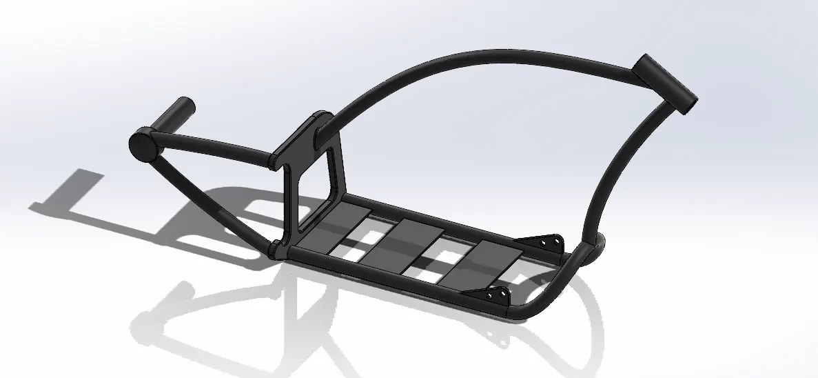
- It is a framework that supports loads. It creates the chopper's skeleton, supporting every component—including the engine, front fork, wheels, and other parts.
- Attach the photo of the blueprint sketch to the mid-plane first.
- Next, draw a curve on the bottom plane as well as the mid-plane. Finally, create a projected curve by using the projected curve tool.
- Once more utilizing the projected curve, draw a second sketch on the right plane and create a curve.
- Now construct a sketch on the mid-plane and sweep a body through the curve using the swept boss tool.
- Next, duplicate the part with respect to the mid-plane using the mirror option.
- Subsequently, sketch anything on the right plane and extrude it.
- After drawing a figure on the generated part, use the extrude cut option to remove some material.
- Next, one edge of the part is given a slight chamfer, and the fillet tool is used to apply different fillets to some of the edges.
- Next, use the Reference geometry option to construct a plane. Next, sketch two concentric circles on the plane. Finally, draw a curve on the mid-plane curve. Finally, use the sweep tool to join the two circles.
- Cut the final portion with the split tool. Next, make a second tool centred on the bottom plane, draw another sketch on it, and make a curve on the mid-plane. A swept portion is then created by using the sweep option.
- After that, remove some of the material from the component by using the split option. Then, put all the pieces that have been made thus far together. Next, build a revolved section by drawing another sketch on the mid-plane and selecting the rotate boss option.
- Remove a portion with the split tool once more. The components are once more joined using the combine tool.
- After sketching on the mid-plane, the merge option is activated and the object is extruded. Various fillets are then served after that.
- To create a portion, another sketch is now drawn on the mid-plane and extruded.
- A split is then administered to extract some material.
- Subsequently, several fillets are provided, and the part for installing the brake lever and kickstand on either side of the mid-plane is replicated using the mirror function. Now, sketch the material on the correct plane. It will then be extruded, and different filets will be applied. After drawing a sketch on the surface of the component formed above, it is cut and extruded, and the appearance tool is used to give the part a final appearance.
Features Used
- Project curve - It helps to get 3d curve which is projected on the basis of two 2d sketches.
- Sweep - This feature creates solid body from 2d sketch profile along a 3d curve.
- Mirror - It helps to mirror half portion
- Extrude boss - This feature is used to convert 2d sketch into 3d object
- Combine - It allows combining two or more solid bodies.
- Revolve - Any profile can be revolved about an axis, centre line or edges and obtain solid bodies from 0 degrees to 360 deg.
- Fillet - This feature is used to convert external and internal edges into rounded shape.
- Dome - This is used to apply dome shape to faces. This allows you to apply domes to irregularly shaped contours.
- Split - This feature is use to split the solid bodies, surfaces and allow us to remove unnecessary portion.
- Plane.
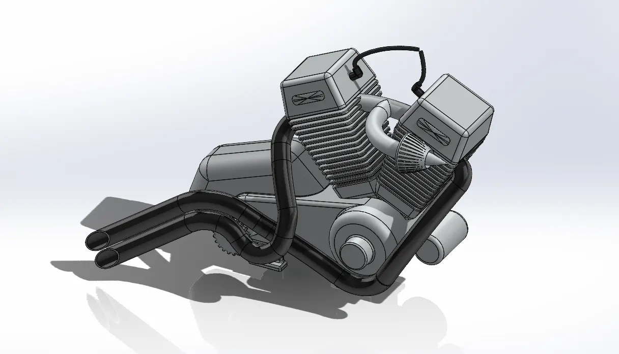
12. Engine
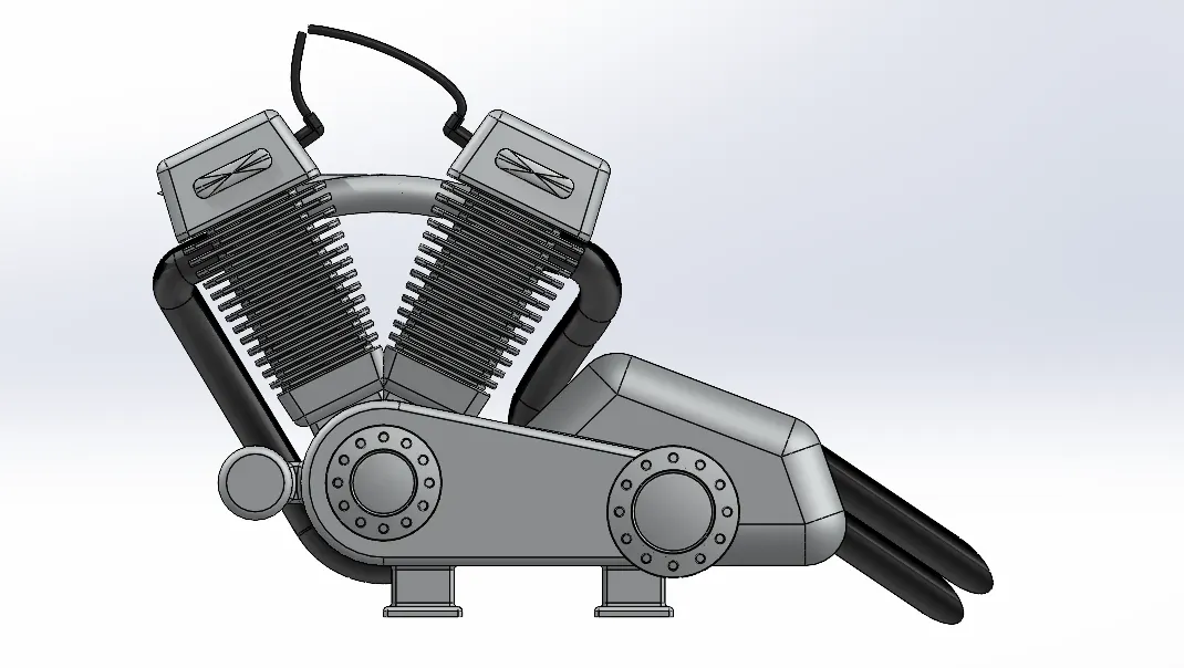
- The motorcycle's blueprint is first put to the front plane.
- Following that, several sketches are made on the front plane, which are subsequently extruded and given fillets. A drawing is now created on the correct plane and rotated to create a portion.
- Next, create a new plane that is in relation to the correct plane, sketch on it, and rotate. After that, extrude and sketch on the front plane. Now, create the chain's teeth by utilizing the circular pattern option. Likewise, repeat the process with the other sprocket. After that, make domes out of the assembled sections.
- To create holes on the sprocket, a sketch is then drawn on the front plane and cut, then extruded. On the opposite sprocket, the same procedure is carried out. The pieces now have specific fillets and chamfers applied to them.
- An additional sketch is then drawn on the front plane and extruded. To create a connecting section, one additional sketch is then produced on the same plane.
- After then, a fresh sketch is made on the front plane, and a new plane is made in relation to the sketch. A sketch is now made on the recently formed plane and extruded.
- On the freshly made plane, two further drawings are made and then extruded.
- Fillets and chamfers are then served to different sides. To build a shape, a drawing is then made on the same plane, cut, and finally extruded.
- Utilizing the linear pattern option, this shape is replicated throughout the section. Various fillets are then applied after that. After that, a drawing is made on the formed cylinder, which is then extruded outward to produce a dome.
- Each side of the cylinder has a mirror image of this shape.
- Following that, a drawing is made on the front plane, which is then extruded and filled in. Some portions are then eliminated by using the split option. Next, use the mirror tool to duplicate the cylinder on the opposite side. The edges are now receiving some fillets.
- After that, several drawings are made on the upper plane, extruded, and given specific fillets. Sketches are subsequently drawn on the front plane, extruded, and chamfered. A tiny sketch is now made on the sprocket, which is extruded, sliced, and given the fillet.
- Next, duplicate the cut all the way around the sprocket by selecting the circular pattern option. A few more chamfers are provided.
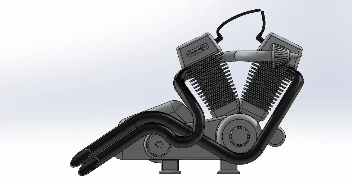
- After that, two further sketches are made: one on the right plane and one on the front. To create the exhaust tube, it is then swept with the sweep tool. The tube is then mirrored after that. Everything that was made is now combined. After that, a plane is made in relation to the upper plane.
- Next, a curve that was previously generated is drawn on another sketch that is drawn on the front plane. The sweeping portion is created using this sketch.
- Once more, an outline is created on the front plane and rotated to create the air intake.
- The portion is covered with a variety of filets.
- After drawing a sketch on the top plane, it is cut out and extruded. The cut is then replicated throughout the portion using the circular pattern tool.
- Next, to construct the exhaust tube Four curves are drawn on two separate planes; a curve is created using the projected curves option, and a sweeping portion is created using the swept option. Likewise, repeat the process with another part. Next, a drawing is made on the upper plane, which will be utilized to cut the exhaust tip with the split tool.
- Next, draw the spark plugs face and an additional curve on the front plane so that the wire for the plug can be made.
- Likewise, use the same process to construct the identical wire on the other spark plug.
Features Used
- Composite Curve - It help to combine two 3d curve.
- Extrude cut - It is used to add pockets, cut-outs, and other features to your current solid model.
- Plane.
- Offset entities - It is used to create same entities on some distance.
- Circular pattern - It is used to pattern the feature circular at require instances.
- Linear Pattern - This pattern is same like circular pattern. But it works like its name linearly along a line, centreline or edge at require instances.
- Sweep - This feature creates solid body from 2d sketch profile along a 3d curve.
- Mirror - It helps to mirror half portion
- Project curve - It helps to get 3d curve which is projected on the basis of two 2d sketches.
- Extrude boss - This feature is used to convert 2d sketch into 3d object
- Combine - It allows combining two or more solid bodies.
- Revolve - Any profile can be revolved about an axis, centre line or edges and obtain solid bodies from 0 degrees to 360 deg.
- Fillet - This feature is used to convert external and internal edges into rounded shape.
- Dome - This is used to apply dome shape to faces. This allows you to apply domes to irregularly shaped contours.
- Split - This feature is use to split the solid bodies, surfaces and allow us to remove unnecessary portion.
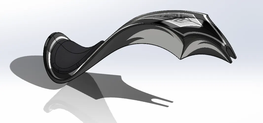
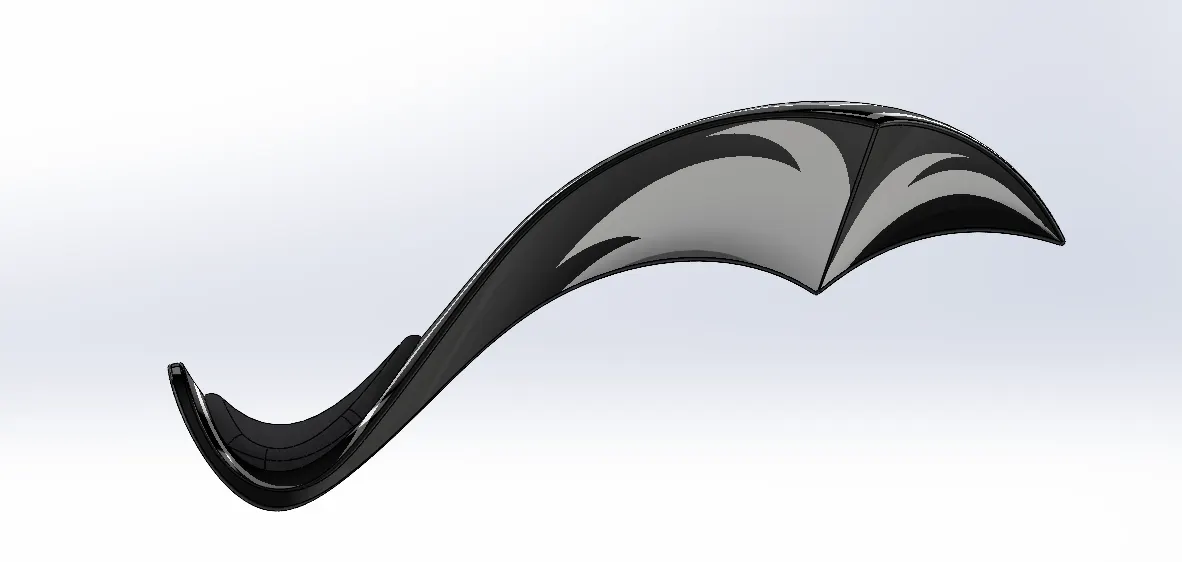
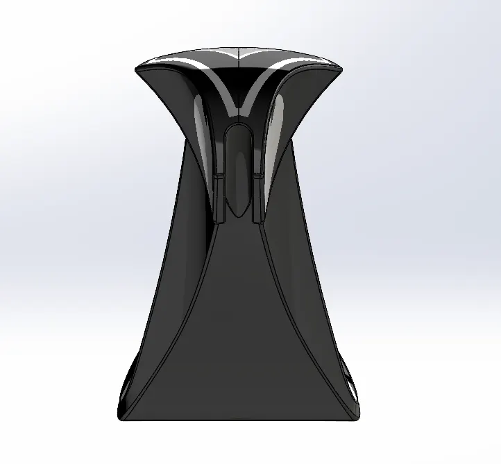
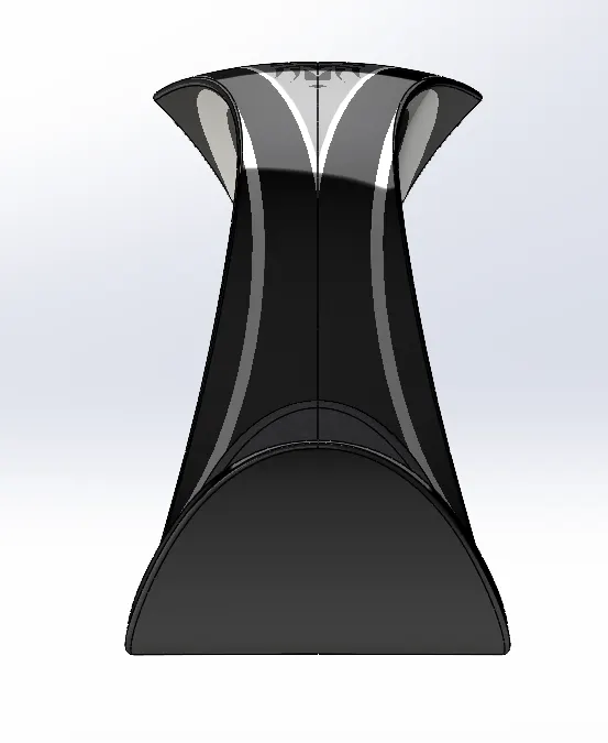
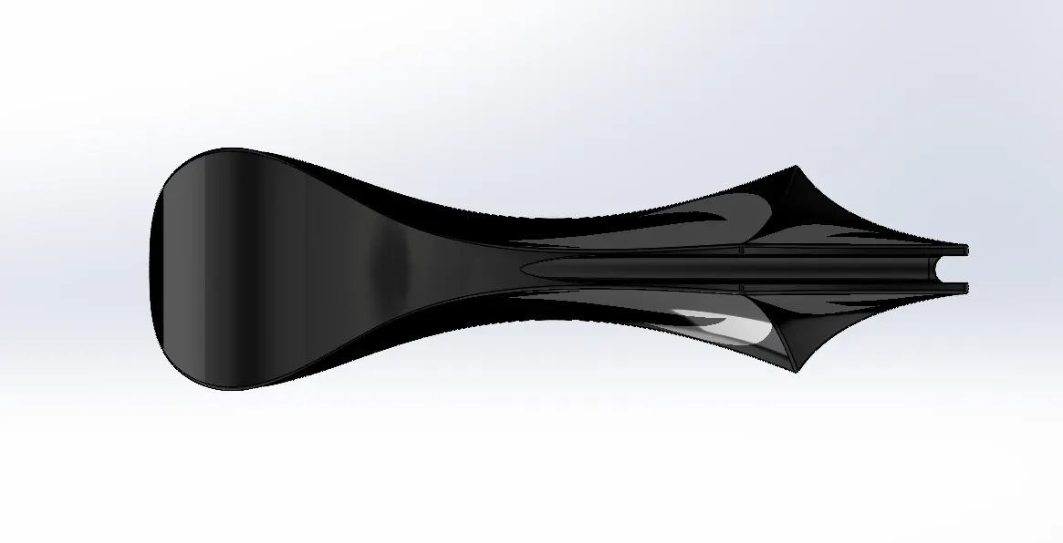
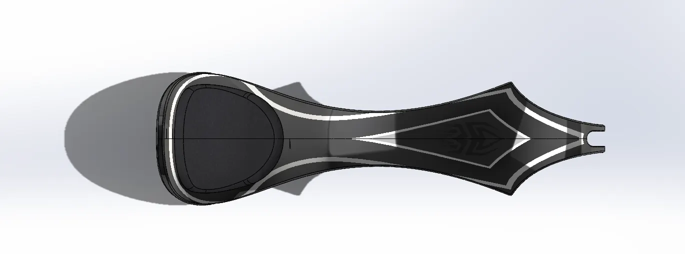
13. Gas Tank
- Gas needed to start the engine is stored there.
- Import the chopper sketch using Sketch, then edit the underlay fuel tank name and proportions.
- Use splines to create a sketch and apply surface sweep.
- Sketch out the design and add surface trim.
- Use project curves to create a compound drawing and add surface loft.
- Make a sketch, add a border surface, and then flip it.
- Use surface knit and divide line command & build a drawing and use surface extrude and create a seat and apply fillets
- Make a sketch, use cut sweep, and store the document.
Features Used
- Sweep surface - It generates surface from section curve positioned along a path.
- Loft surface - It create surfaces between existing edges by creating smooth tangency between selected curve.
- Extrude surface - It convert projected surface into 3d surface.
- Boundary surface - This feature create surface between boundaries or edges but specifying both directions.
- Surface Knit - This feature is use to combine two or more surfaces to make one solid body surface.
- Surface Trim - It is use to remove unnecessary surface.
- Sweep cut - It is use to cut solid bodies along a path.
- Fillet - This feature is used to convert external and internal edges into rounded shape.
- Shell - This feature hollows out part, leaves open the faces selected and creates thin walled feature on remaining faces. Also, it creates closed hollow model.
- Mirror - It helps to mirror half portion
5. ASSEMBLY
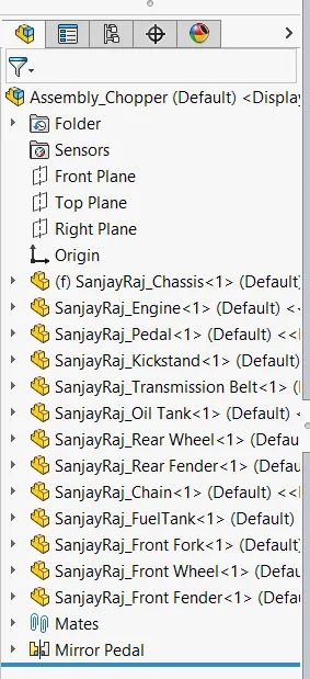
In order to begin assembly, Open a fresh assembly file. During assembly, each component must be inserted one at a time, after which the parts must mate with one another.
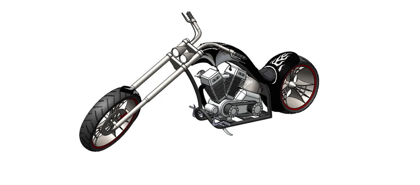
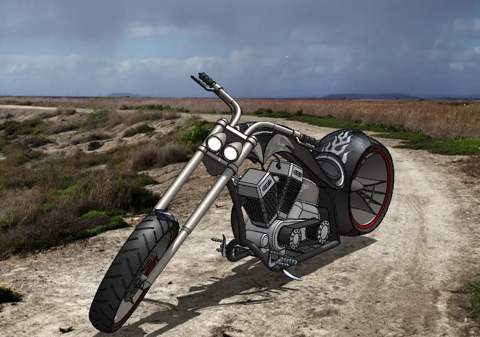
Rendered Image
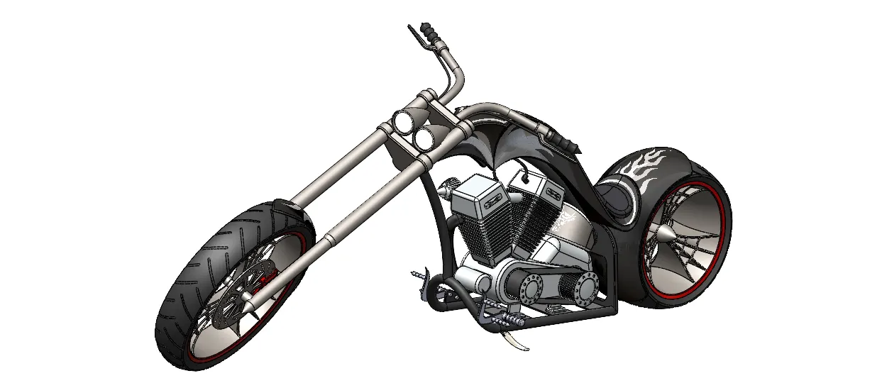
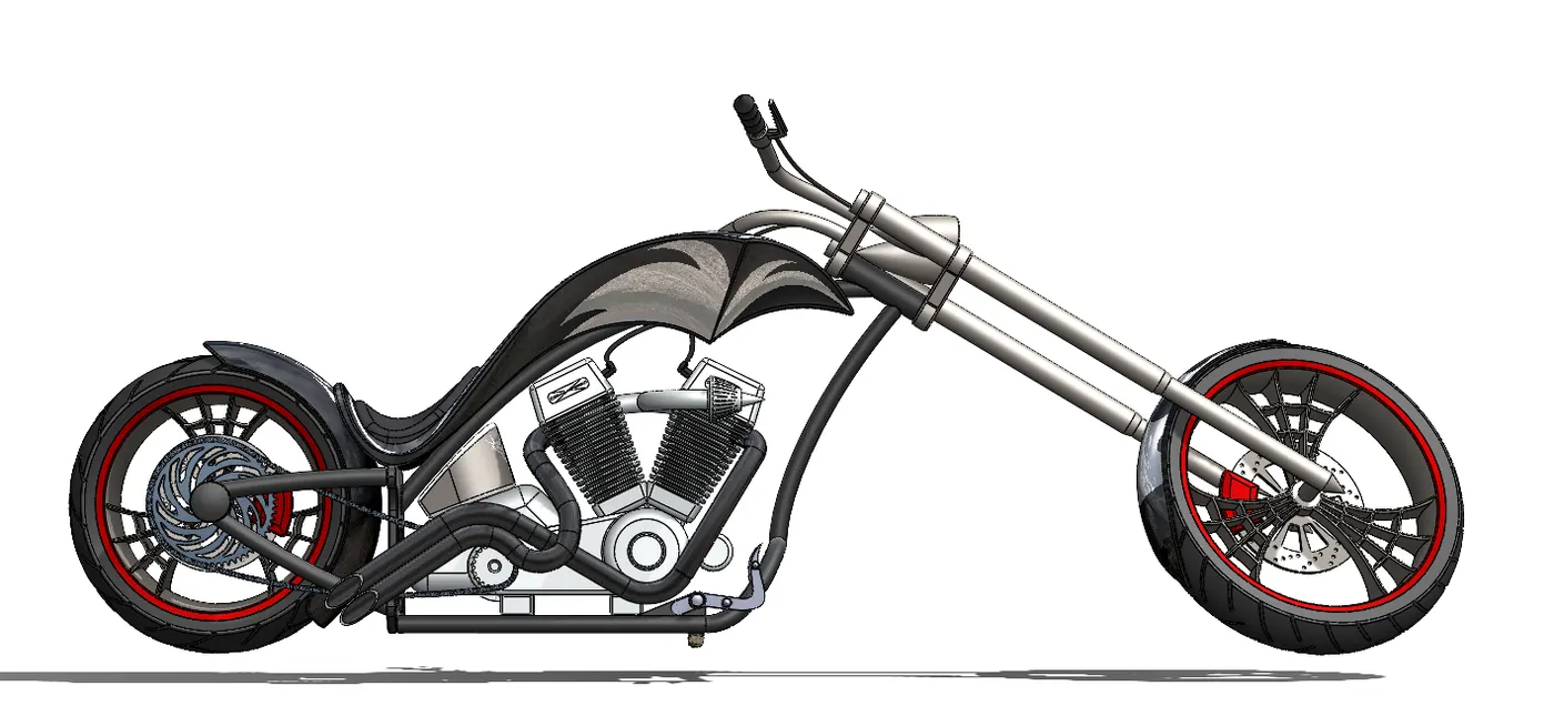
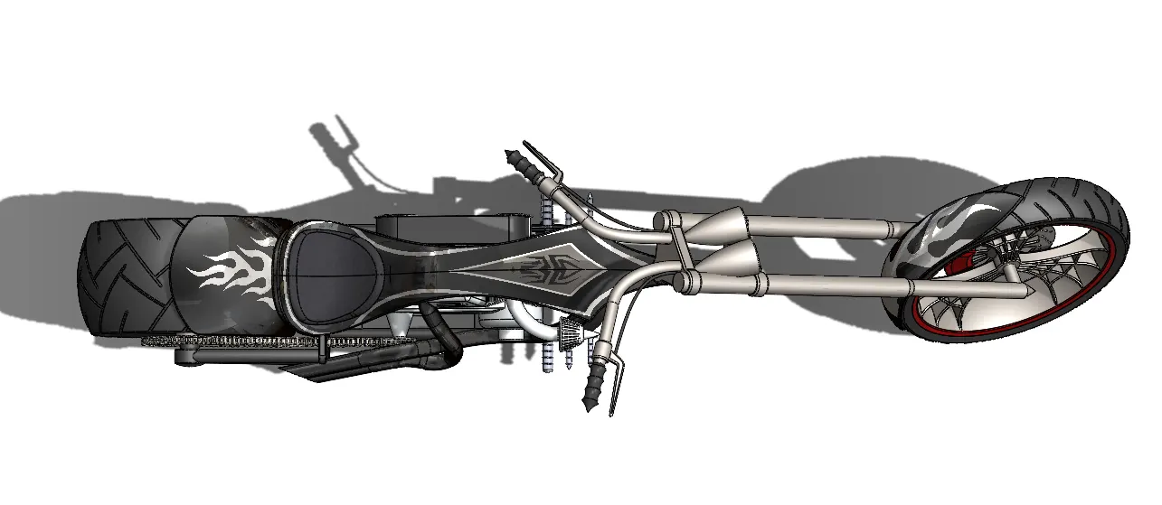
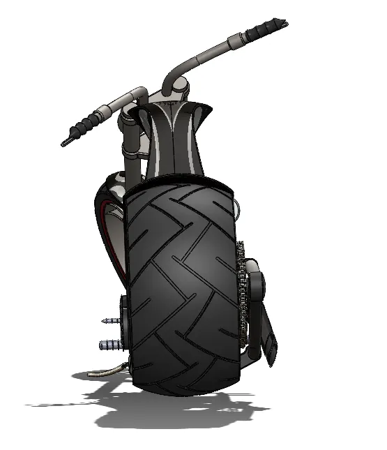

Features utilized during assembly:
- Insert part.
- Mirror.
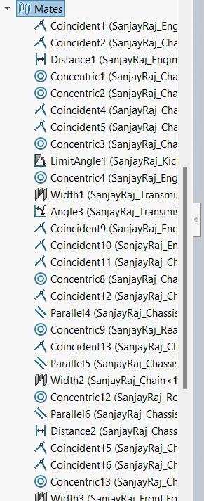
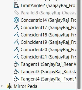
- Mates. - Mates are used to establish relationships between parts based on how those parts operate. We must define the mates based on our current circumstances and the desired appearance. Relations that mates uses are Width Mate, Angle, Tangent, Concentric, Parallel, and Coincident.
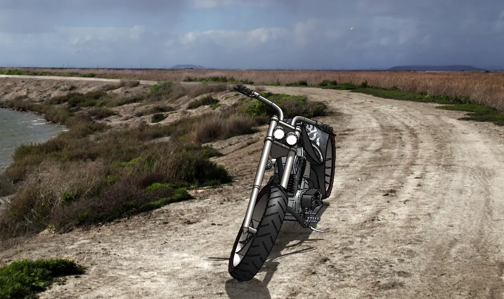
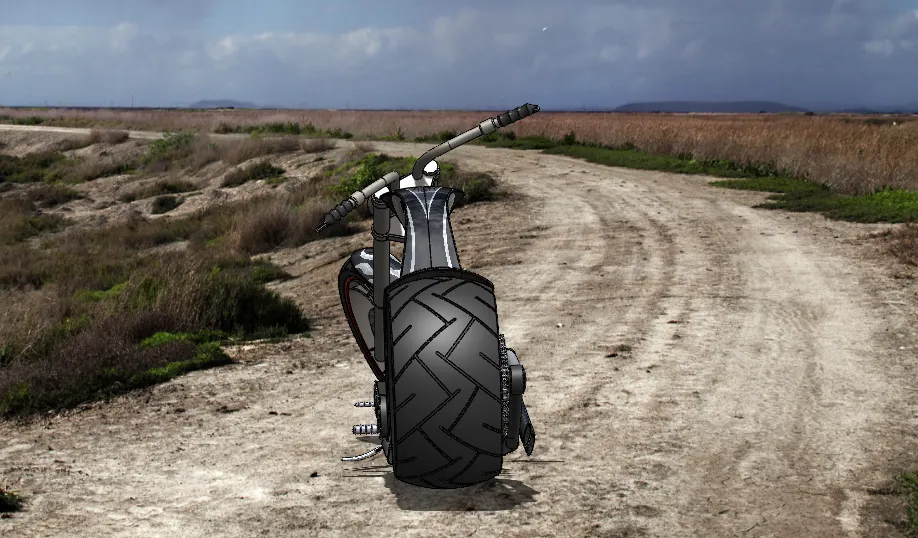
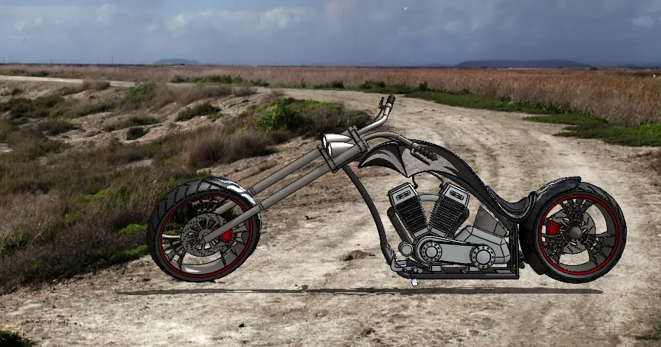
6. PHOTO REALISTIC RENDERING
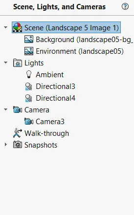
The process of producing a realistic visual model in an actual setting is called rendering. SolidWorks Visualize and Photoview 360 are the two methods available for rendering.
CONCLUSION
Learned comprehension of SolidWorks' user interface. Using SolidWorks' solid modelling capabilities, I partially modelled an American helicopter. Knowledge of the capabilities and adaptability of SolidWorks modelling. In SolidWorks, the parts are put together to create the final assembly. SolidWorks visualize and Photoview 360 produce a realistic image.
File - https://drive.google.com/file/d/1sFzsReYLFwYgP_zPjFhKdx6u_YCatonu/view?usp=sharing