Photo Realistic Rendering
PROJECT
MODELING OF AMERICAN CHOPPER BIKE ON SOLIDWORKS
Objective:- To Prepare a complete model of an American chopper bike using Solidworks software.In this project
all the parts of the chopper bike will be modeled and assembled in a single assembly file. This project will help you to build up the basic and advanced level knowledge in Solidworks because this project has no. of parts and all have a different tool concept. And the last rendering will be done to 360 photo view.
Introduction:- This is a modeling of an American chopper bike on SolidWorks.In this project, all the parts of an American chopper bike are modeled and assembled in a single file. At the end of the project, we will be able to know different types of tools and their uses in many situations. In Solidworks, there are various tools that can perform similar actions but which one is more effective is an important thing and we will learn all these things.
American Chopper Bike specification:-Engine capacity---2025.7cc
Mileage -----19km/l
Gears ---------6
Brake ---------- Disc
Fuel tank capacity-----17.0L
Wheel Type --------Alloy Wheels
Starting mechanisms----- Self Start
Different parts of the bike are to be modeled here are as follows----
1. Chassis
2. Engine with exhaust system
3. Front wheel
4. Rear wheel
5. Front Rim, Rear Rim, Disc plate, and calipers.
6. Front and rear fender
7. Oil tank
8. Gas tank
9. Chain and transmission belt
10. Kickstand and foot pedals
After designing all the above parts we have to assemble these in a single file to complete the whole bike feature. After that
rendering is done to 360 realistic photo view.
Design approach:- It is a very important thing while designing multiple parts of a model. Here designing approach is shown in Design layout.
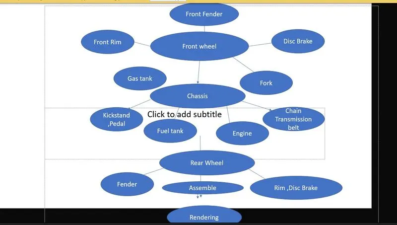
Important Tools which I have used in this project:-
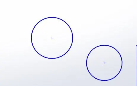
1. Sketch tool:- The sketch tool is a very primary tool because anything whatever we want to model first we have to make a 2D sketch, so the sketch tool is very handy and important. There are various sketch tools like line, circle, rectangle, Sketch fillet, spline, polygon, etc.
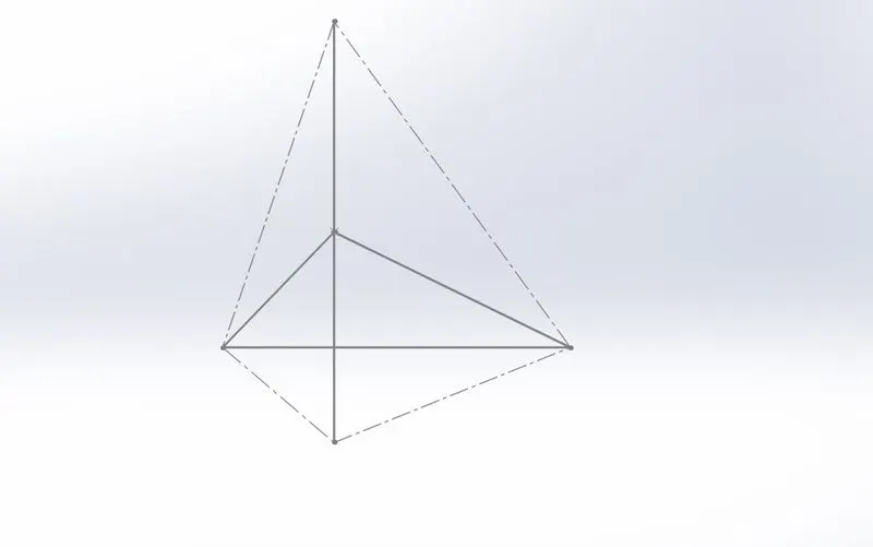
A. Line:- This tool is used to draw lines like a straight line, midpoint line, construction line.
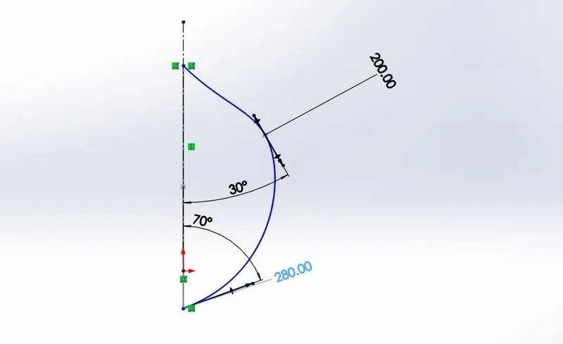
B. Spline:- Spline is used to draw a curve line by adjusting the spline handle and handle weight value. This is very handy to draw any complicated curves.
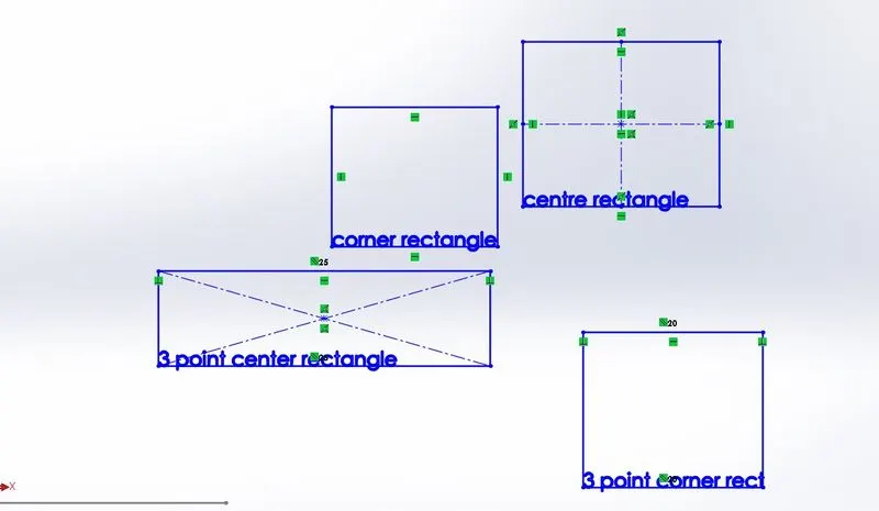
C. Rectangle- This tool is used to draw rectangles very quickly. there are various types of rectangle tools---
1. corner rectangle
2. center rectangle
3. three-point center rectangle
4. three-point corner rectangle etc
D. circle-it is used to draw circles and perimeter circles.
2. Features tools:-
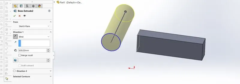
A. Extruded boss /base:- it is used to extrude solid body at any length. it has many features like direction setup, thickness set up, extrude reference set up, etc.
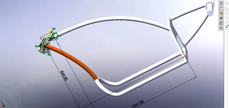
B. Revolve Boss/Base:- This tool is used to make solid having curve surfaces, different types of solid can be made have curvature-like surfaces, the sketch is revolved about an axis. it is similar to extrude base but it has only a curve surface.
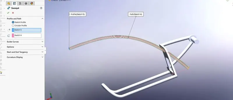
C. Sweep Bose \Base:- It is used to connect two sketches on a different plane or on the same plane in order to make a solid body.in this tool, many features are available as a guide curve, surface curvature, thin features.
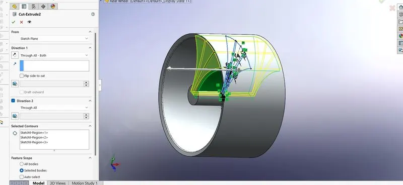
D. Extrude cut:- This tool is used to extrude materials from a solid body. To extrude materials first draw a sketch according to requirement and then apply the extrude cut command. It has many features like surface offset, reverse, direction.
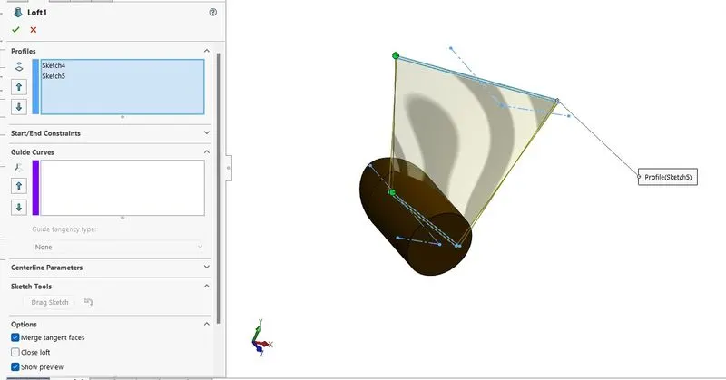
E. Lofted Boss /Base:- This tool is similar to sweep boss/ base but it can create solid features between two different planes.it is a very handy tool to create a solid body.it has also many features to create different types of surfaces.
Parts of American Chopper bike:-
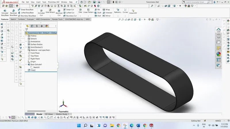
1. Transmission belt:- Transmission belt is a very important part of this bike. transmission belt transfers power from the engine to the rear wheel. It is made up of rubber, synthetic fabric.
Its sketch is very simple, first take a plane and draw a sketch and then just apply to extrude boss base.
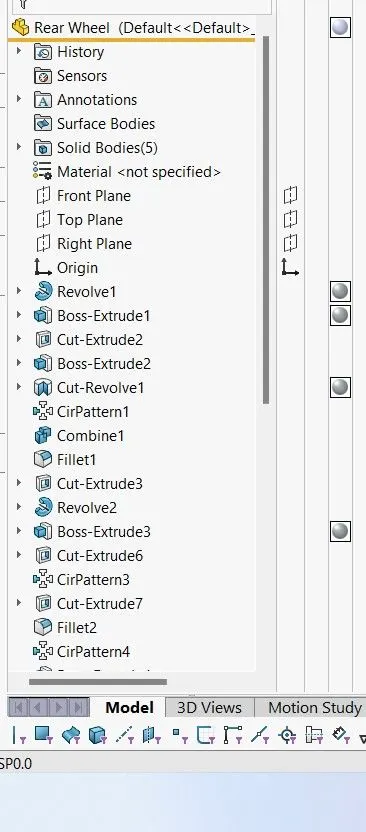
2. Rear Wheel:- the sketch of the rear wheel is little bit complicated because it contains many parts like rim, tire, disc plate, caliper, and sprocket. all are in a single file.
1. draw the sketch as shown in databook
2. Apply to revolve boss base
3. draw sketch and apply extrude boss /base .and so on
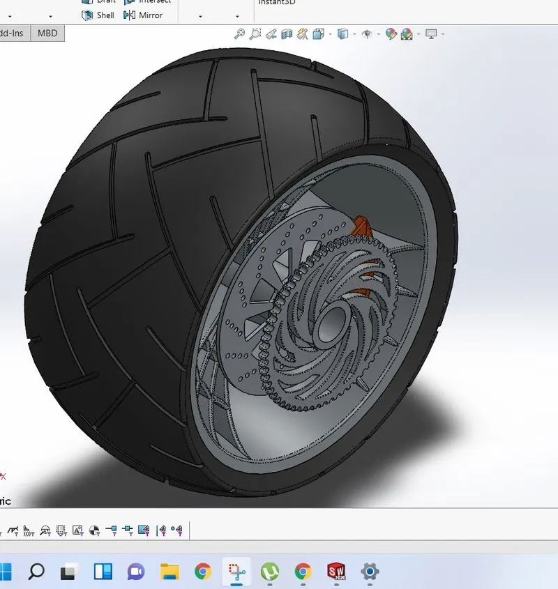
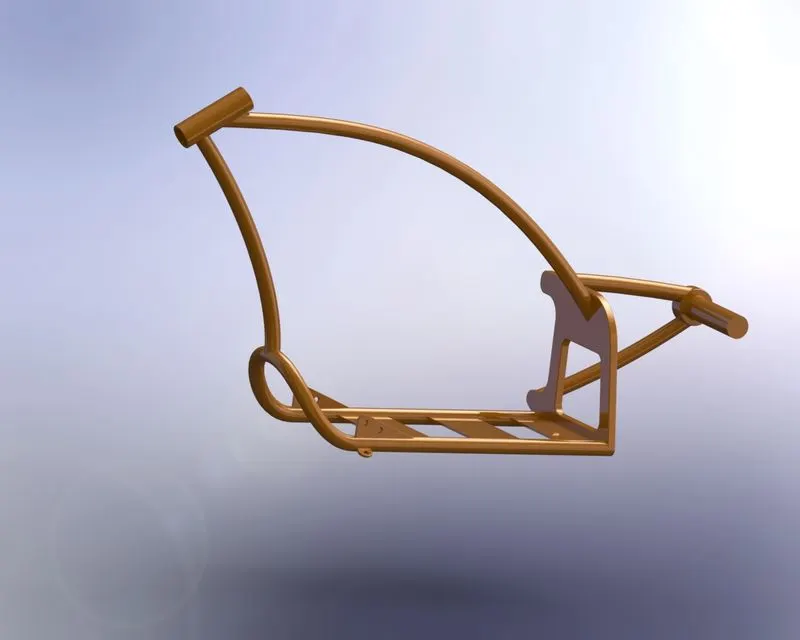
3. Chassis:- The frame structure of the vehicle is called chassis. all the parts of the vehicle are assembled to the chassis.It is like a backbone of a vehicle. It provides stability and support to the whole body of the vehicle.
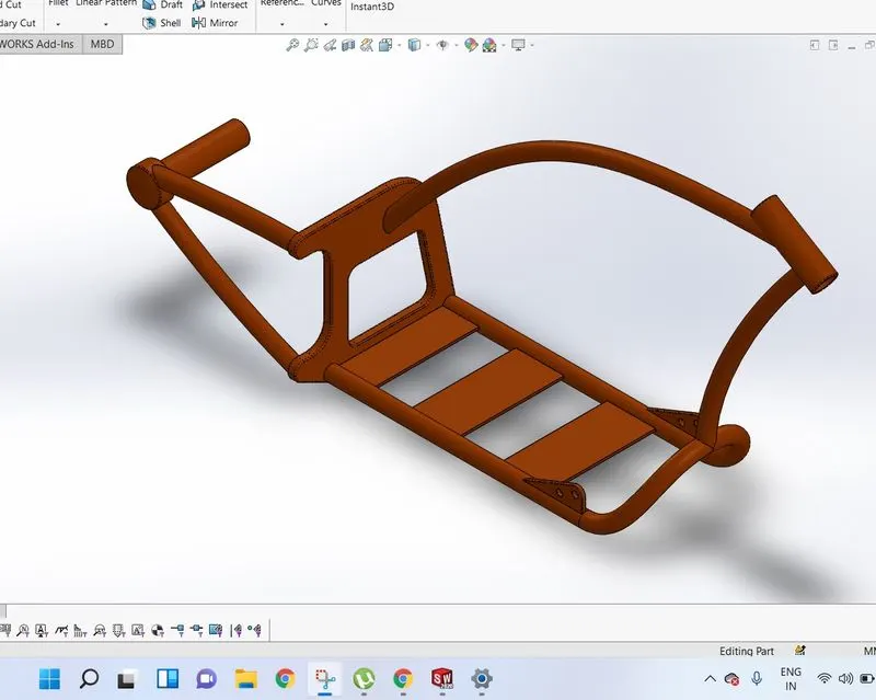
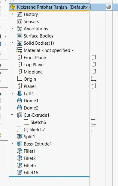
4. kickstand:- It is a small part of the bike. kickstand helps to park the vehicle. the kickstand is a simple model and a sketch of a kickstand is also simple.
First select plane and start sketch using spline, circle, and line
go to feature and select lofted boss/base.
Apply dome on the outer surface like this......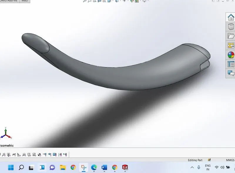
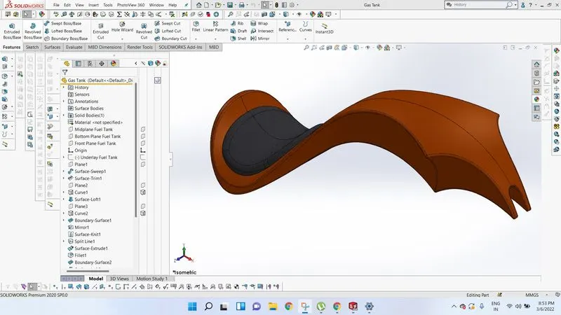
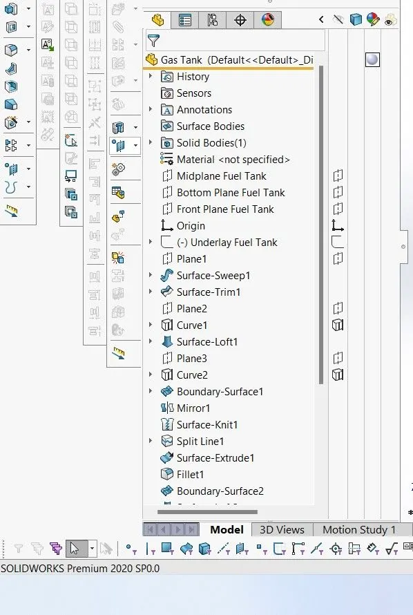
5. Gas Tank:- Gas tank is like a vessel to store fuel. The gas tank also provides the look of the whole bike.in this chopper bike
seat is attached to the gas tank.so it requires special attention while modeling the gas tank.
First of all, select a plane and start sketching. go to tool<sketch tool<sketch picture<select the blueprint of the gas tank and click ok.
now adjust the sketch picture according to pdf.
Start a new sketch on side plane and add lines and spline according to blueprint.
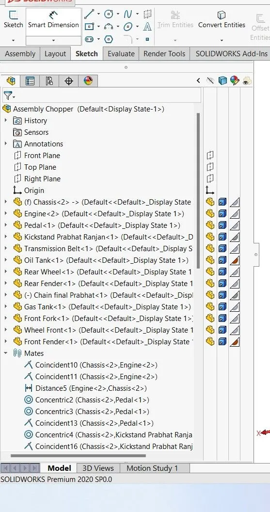
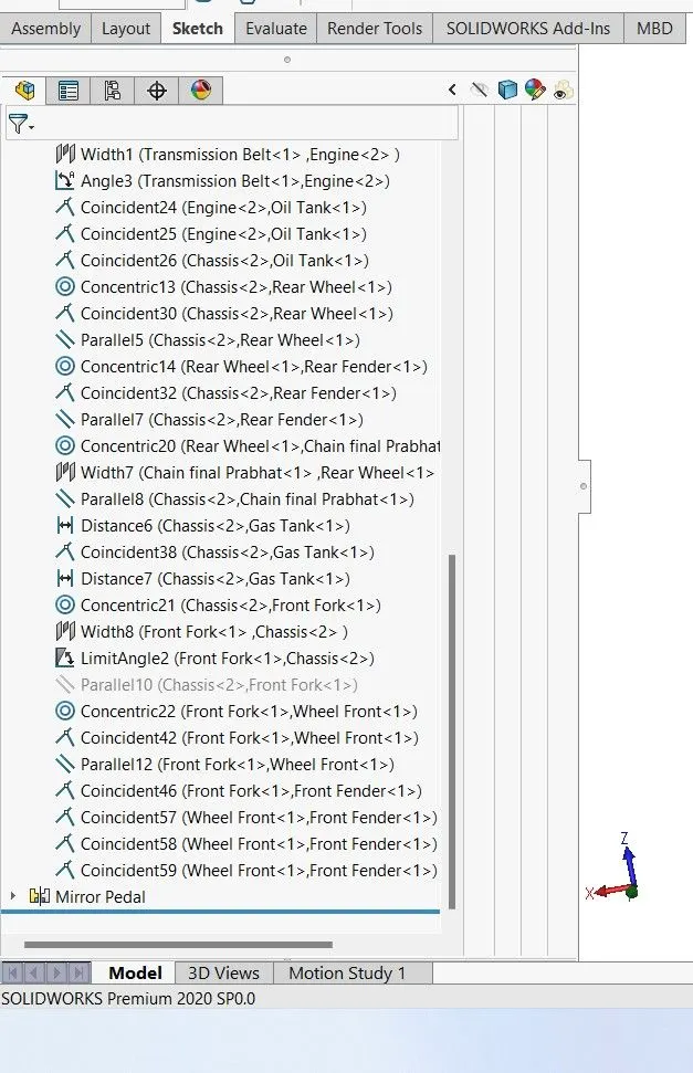
Assembly:- Assembly is the final step of preparing a model. in an assembly file we insert all the parts according to plane and coincident faces by use of proper mate tool options.
Go to new file option<assembly and click ok.
first, make visible all the planes of the assembly environment.
first, insert the chassis and match the plane of the chassis file to the assembly file plane and say ok.
similarly, all the parts files will be inserted and mate will be done.
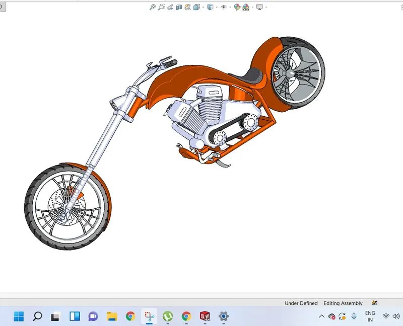
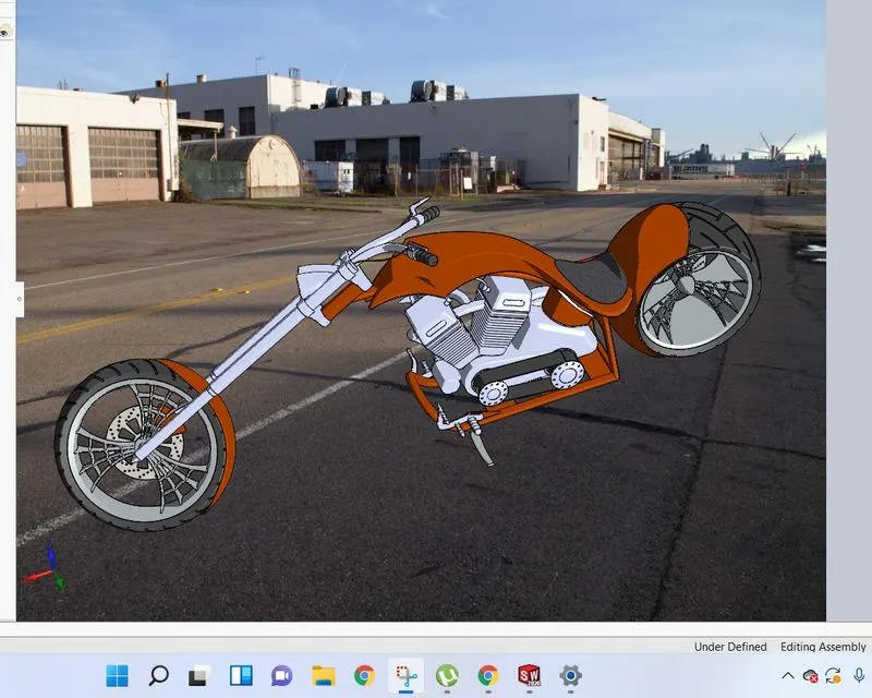
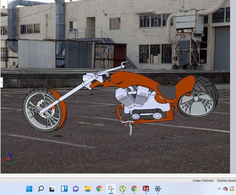
Here is a complete assembly file of an American chopper bike...
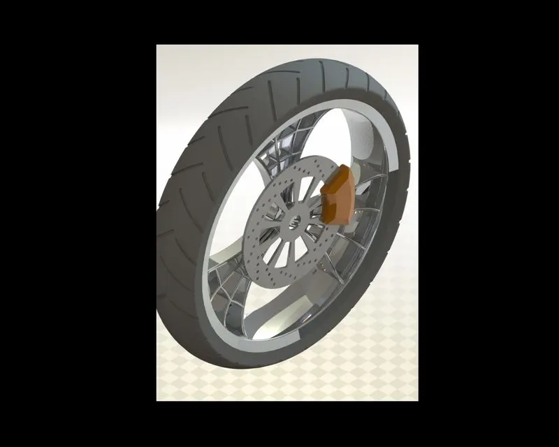
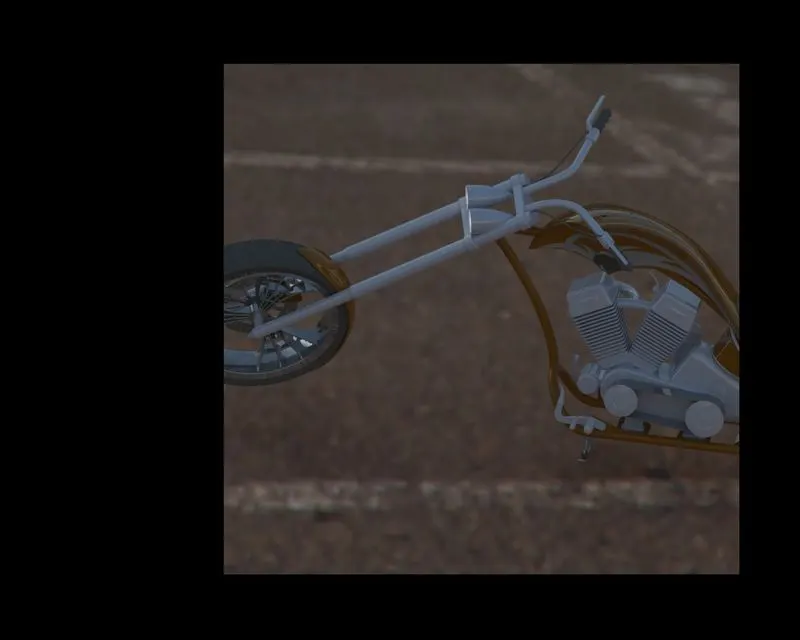
Rendering:- Rendering is a very useful tool in Solidworks. Rendering is done of any component to get a realistic view. The rendering tool gives 360 photo view. Solidworks gives a very handy tool called visualizer, this visualizer gives perfect 360 photo view. here are some rendered images that I have done.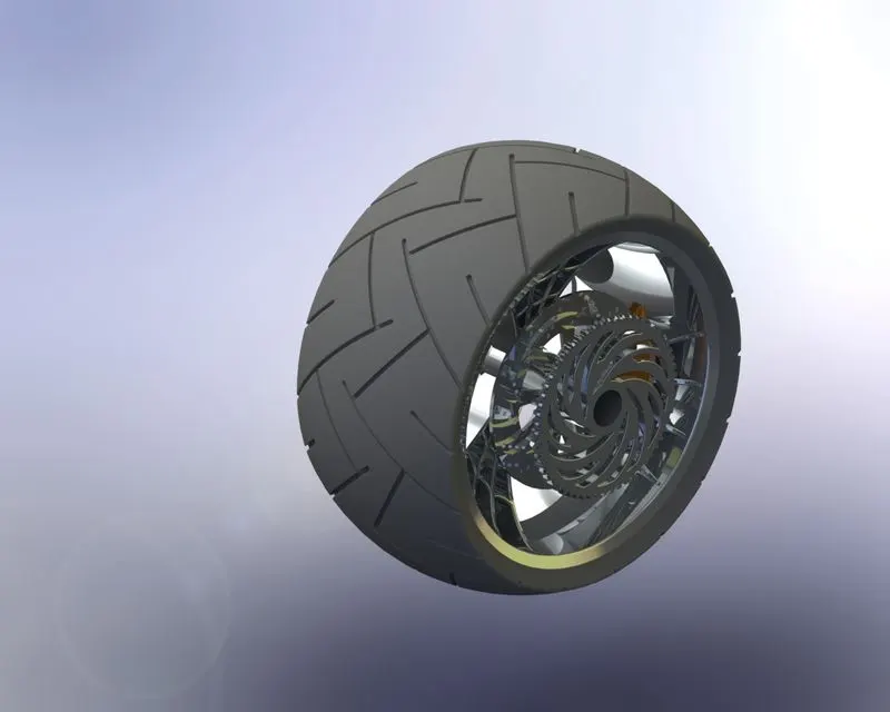
Conclusion:-All the parts of the American Chopper Bike are modeled as per dimension and feature appearance successfully. Assembly is done in a single file successfully. All the parts and main assembly are rendered successfully. And hence the project is completed successfully.
https://drive.google.com/file/d/1C8JIFx32iAluS58Ju1pVKPnaFyR23WMn/view?usp=sharing
Thank you
Prabhat Ranjan
https://drive.google.com/file/d/1C8JIFx32iAluS58Ju1pVKPnaFyR23WMn/view?usp=sharing
;-