Internal Geneva Mechanism
Project Name:- Internal Geneva mechanism
Objective:- To create 3D models of the driver and driven wheel to perform the geneva motion mechanism. Assembly of wheels in assembly file with proper constraints and perform motion analysis of the wheels and plot the graphs of contact forces, angular displacement with various numbers of frames, and angular velocity.
The basic concepts of the geneva mechanism:-
Geneva mechanism is a mechanical mechanism in which continuous rotary motion is converted into intermittent motion. Intermittent motion means moving and stopping in a fixed interval of time. Such type of motion is required in automation systems like belt conveyors, food packaging, product manufacturing process, assembly work station, etc.
The minimum no of the slot on the driven wheel is 3 and the maximum is not more than 18. The advancement of the driven wheel in one revolution of the driver wheel depends on the no of slots.
360/n advancement will occur in the driven wheel in one revolution of the driver wheel.
where n is the number of slots.
Here I have taken 4 slots so 90-degree advancement will occur in one revolution of the driver's wheel.
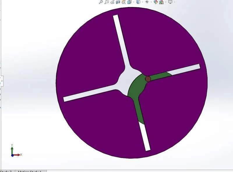
Design process:-
Start sketching with a circle on the front plane.
Make slots as per the given dimensions.
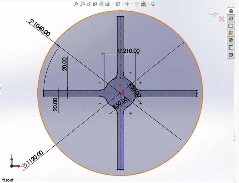
Now use the Feature command and apply it to extrude boss base.
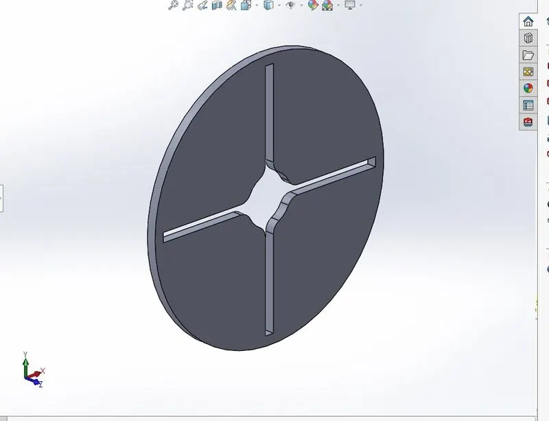
Now modeled driver wheel
Go to the new part file and start sketching in the front plane.
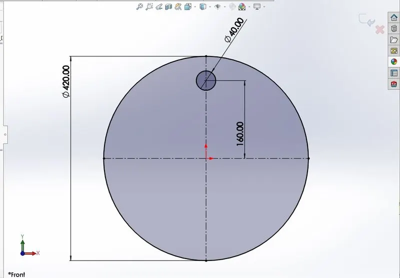
Go to feature
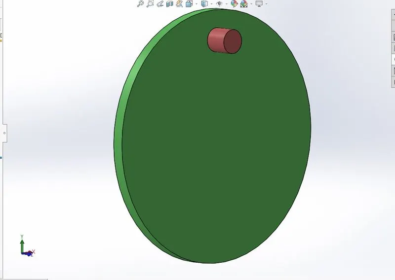
Assemble the driver and the driven wheel.:-
Open a new assembly file
insert both wheels one by one.
Now apply mate make a proper constraint of driver wheel so that it will only rotate about its axis.
now try to adjust the driven wheel in a proper position to perform the geneva mechanism.
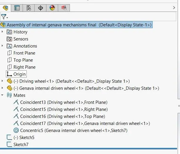
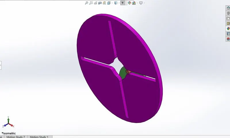
Now it's to create motion analysis:-
Go to add-ins
Open motion study.
First of all, add a motor with a constant rpm of 10 to the drive wheel.
Add contact relation with driven and drive wheel.
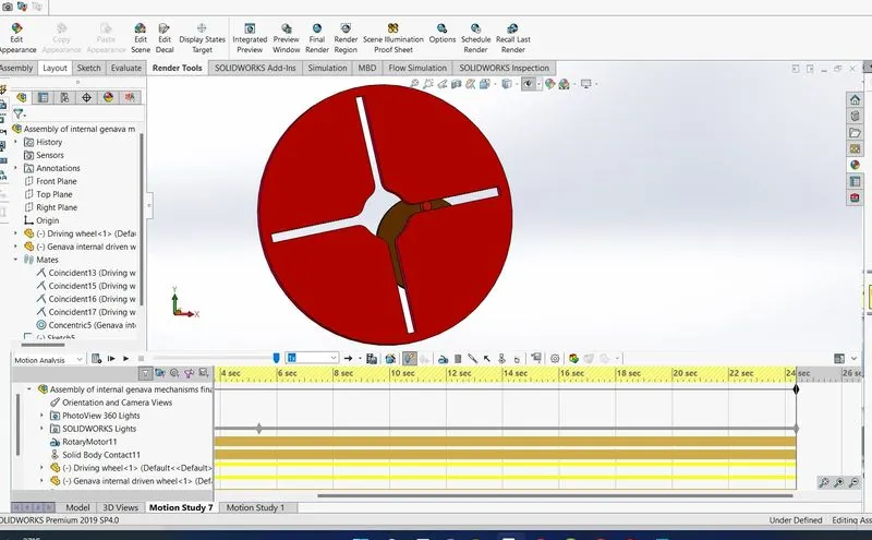
Results and graphs of this motion analysis:-
1. Contact force between driver and driven wheel.
The driver wheel is getting power from the motor having a constant speed of 10rpm.
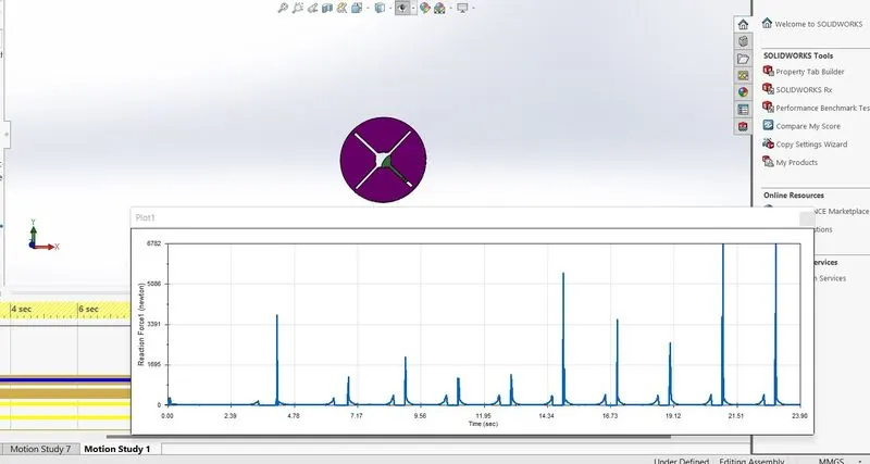
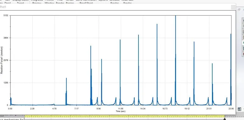
Contact force with precise contact.
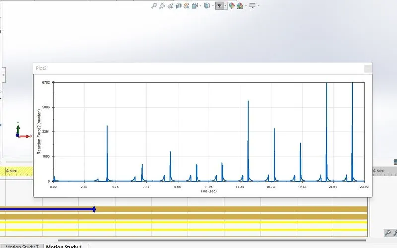
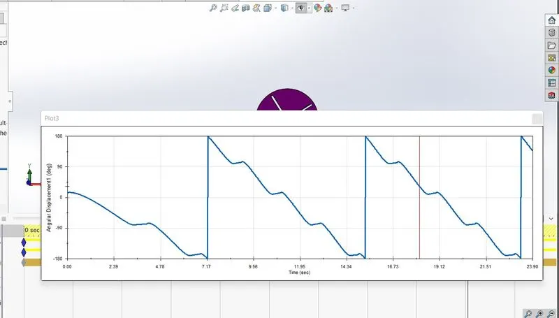
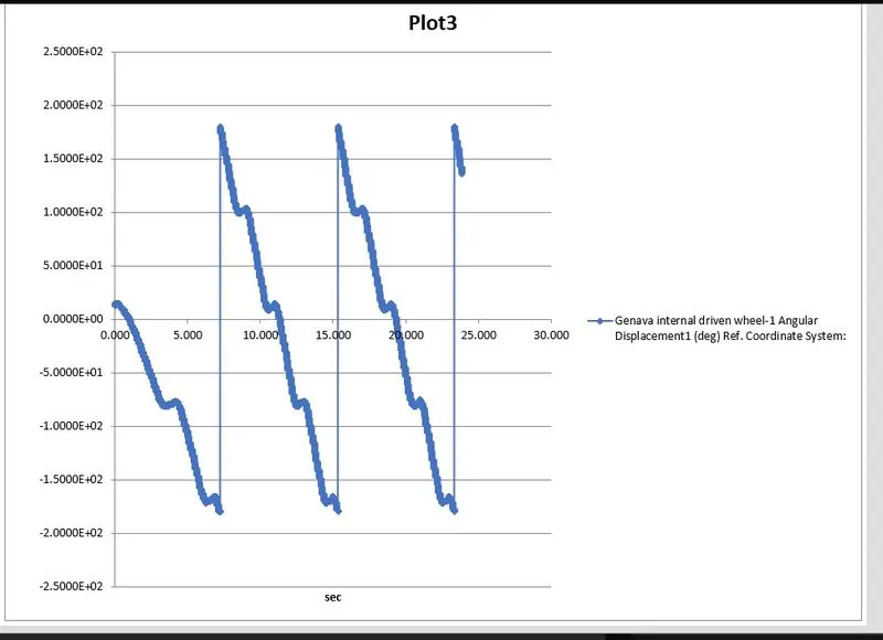
Angular Displacement of Driven wheel:-
Displacement graph on excel.
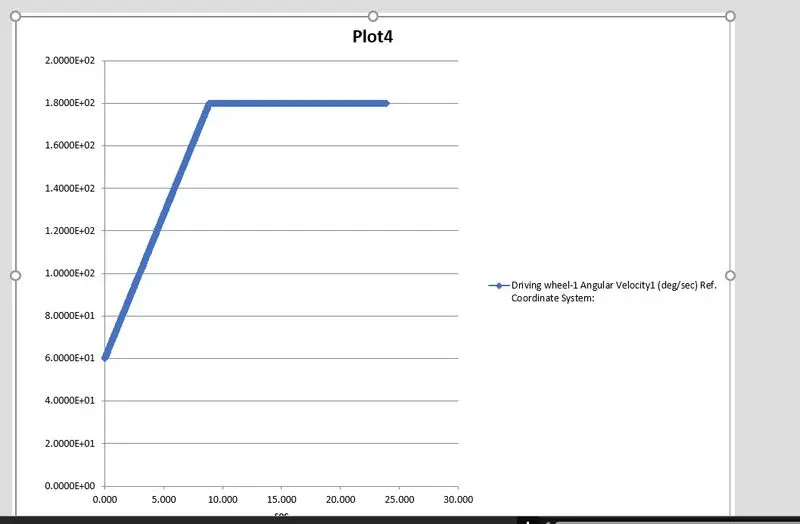
Angular Velocity:-