Boeing-747 _ Final_Project
Project -Boeing 747-8
{Modeling And Assembly Of Parts Of Boeing 747-8 Using Solidworks}
Aim—
.To sketch and model every exterior part of the Boeing 747-8 Aircraft under the part modeling and main body fuselage
.To assemble the modeled parts in the assembly section in Solidworks
.To create a photo-realistic rendering of the Boeing 747-8 using the Render tool
What is Part modeling?
Modeling is the creation of a virtual prototype of an item. It can be used for various purposes. just consider a car engine, each part of ts of industries.
The Boeing 747-8 is the advanced creation of an American aerospace company. It is the latest variant of the 747 after introducing the 747-400. The 747-8 was the first lengthened 747to go into production and the second 747 version with a fuselage of modified length after the shortened 747sp.
The passenger version named 747-8 was formally launched on 14,2005 by Boeing. it can carry up to 410 passengers in a typical three-class configuration over a range of 8,000 nm (14.310) at Mach 0.855
Wingspan 68.45m
Length 76.25m
Height 19.35m
Power plant
Engine model general electric Genx
1 Blueprint Set Up
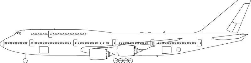
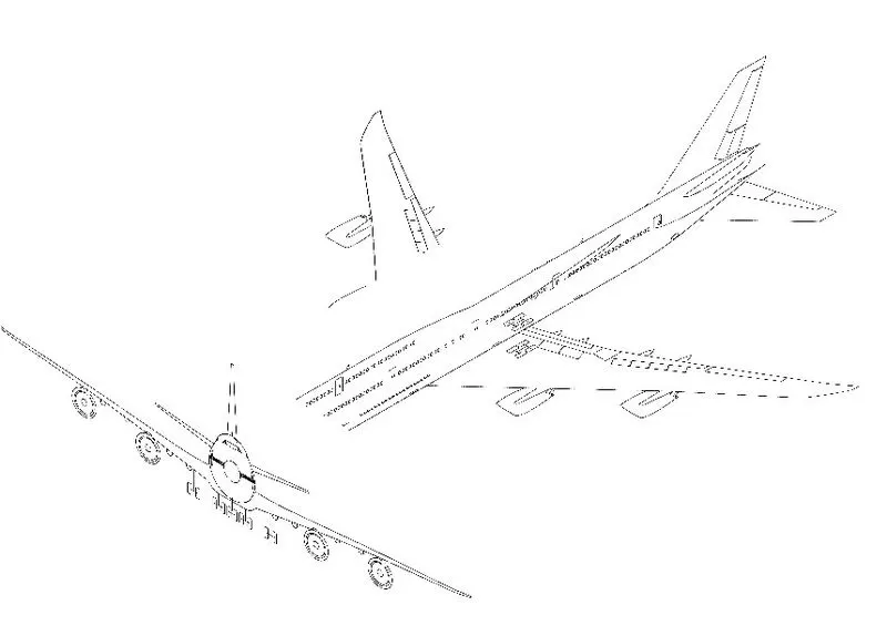
There are three views (front, top, and side). All views must be matched with their respective planes and add dimension as above given.Images(Front,Top, Right view) are inserted in the drawing area by using the tool command
2 Fuselage-
The fuselage is an aircraft’s main body section.it holds crew, passengers, and cargo .in single-engine aircraft will usually contain an engine, as well, although in some amphibious aircraft the single engine is mounted on a pylon attached to the fuselage, which in turn is used as a floating hull .fuselage also contain other parts like pitot tube, vertical and horizontal stabilizer, door, hatches window, cockpit and many more.
. Draw a sketch of a blueprint by using sketch tools like line, spline, circle,
. create a projective curve by using two edges of the blueprint top view and side view.
. Now create section planes no around12 to 15 to make curvature body
. Draw a sketch on every section plane and makes a pierce relation and provide appropriate tangent relation of the spline handle.
.After completing the sketch applies the Lofted boss base to create a solid body.
. Don’t forget to apply a shell thickness of 50mm.
3 Belly Fairing-
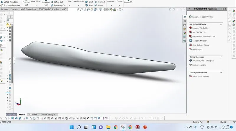
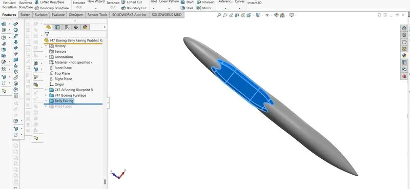
Belly fairing is also called s “Ventral fairing”.It is located on the underside of the fuselage between the main wings. It can also cover additional cargo storage or fule tank and other luggage
.sketch on the right plane and add dimension
.Apply extruded boss base and extrude the materials.
.Apply fillet as per dimension aspect.
. Mirror the half part of the belly fairing of the left side to the right side.
4 Nose cone-
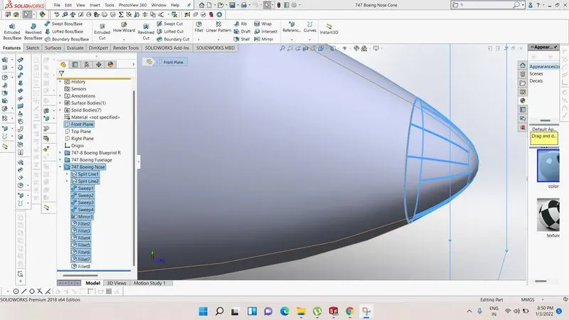
The nose cone is the foremost portion of the plane. It's a very important part of a plane because it resists high currents of wind and also no of small particles strick to the nose cone while the plane is flying. So the nose cone is coated with special material which has good damping properties and must be an insulator. On airliners, the nose cone is also used for protecting the weather radar from the aerodynamic force.
5 Pitot tube-
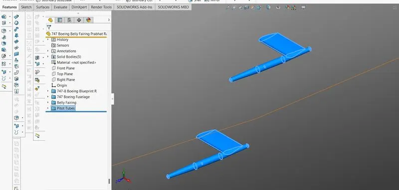
A pitot tube is a flow measuring device used to measure fluid flow velocity.Basically, a pitot tube is used in wind tunnel experiments and on airplanes to measure flow speed. There are four pitot tubes available in the 474-8 aircraft.
.Dwaw sketch on the right plane
.Apply swept boss base to create pipe
.Apply some large value fillet
.Mirror the pitot tube to the other side
6 Cockpit window-
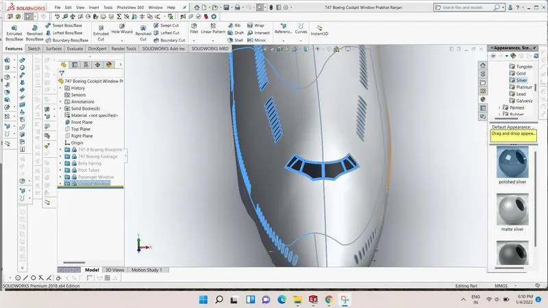
It is the pilot window, as per the name cockpit, the cockpit is the front section of the plane where the pilot's seat and control of the plane are set up. It is at the front section so the window material must be good hard so that small particles could not penetrate it and it must be clear transparent so that pilot could easily navigate the plane.
.Draw a sketch on the front plane and apply a split line to the body.
.Add 0mm surface offset and thicken the surface offset.
.Add appearance glass black.
7 Pssenger Window-
A cabin window consists of three panes
1. An outer pane flush with the outside fuselage.
2. An inner pane that has a little hole in it .
3. A thinner non-structural plastic pane called a sketch pane.
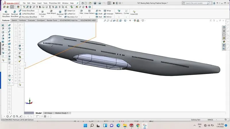
Boeing 747-8 has 250 passenger windows.The outer pane is 12mm thick and the inner pane is 4mm thick.
.Sketch on the right plane
.Add split line and apply surface offset
.Apply linear pattern and complete the no of windows
8 Door And Hatches -
There are 6 doors on each side of the Boeing 747-8.The top above the cockpit the cockpit escape hatch is placed .On the right side of the fuselage there are 3hatches available .One at the front two at the rear side of the fuselage.The plug door is often seen on aircraft with pressurized cabines.Due to the air pressure within the aircraft cabin being higher than that of the surrounding with multiple pins or hatch dogs to prevent opening while in flight.
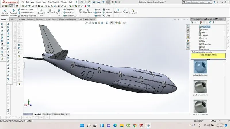
9 Light And Antennas
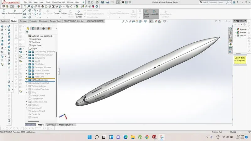
There are two light and three antennas as created in the Boeing 747 -8 model.The lights are on the back side of the cockpit.The two aantennas are in the top of the fuselage .Red light gives indication of plane and antennas stablish realation to the ground and makes able to communicate with pilot and ground staff.
There are different types of antennas available in the aircraft .The following are the the common antennas
.Communication antenna
.GPS antenna
.Loran antenna
.Loop antenna
.Maker beacon antenna
.Nav antenna
.Radio altimeter
.UHF antenna
10 Auxiliary Power Unit
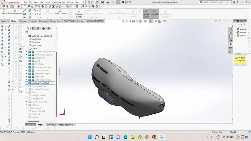
An auxiliary power unit (APU)is a device on a vehicle that provide energy for function other than propulsion .They are commonly found on large aircraft and naval ships as well as some large land vehicles.
11 Vertical Stabiliser
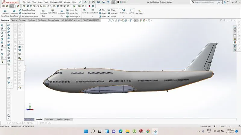
Vertical stabiliser is a very important part of plane .It provide stability of aircraft and help to setting nose up and down .The vertical stabiliser keeps the nose of the plane from swinging from side to side ,which is called Yaw.
12 Horizontal stabiliser
Horizontal stabiliser of aircraft it helps plane to turn right and left and also make balance right and left .horizontal stabiliser has fins which is movable and adjustable according to need .It controls up and down motion of nose called pitching
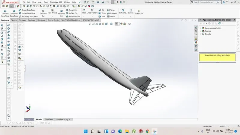
13 Wings-
A wing is type of fins that produce lift and drag force.these forces are very important for fly because at time at take off of plane requires lift force and at time to landing it requires drag force to slown down the speed .wing also provide horizontal stability .wing holds ailerons and brake flaps.wing is a hollow body in which fuel is stored or called fuel tanks.
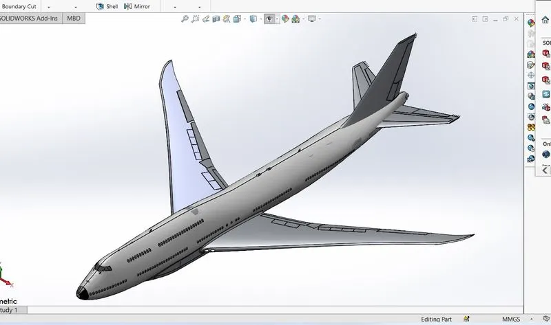
14 Flap,Ailerons,Flap Track Fairing
All are attached with wing of the aircraft .
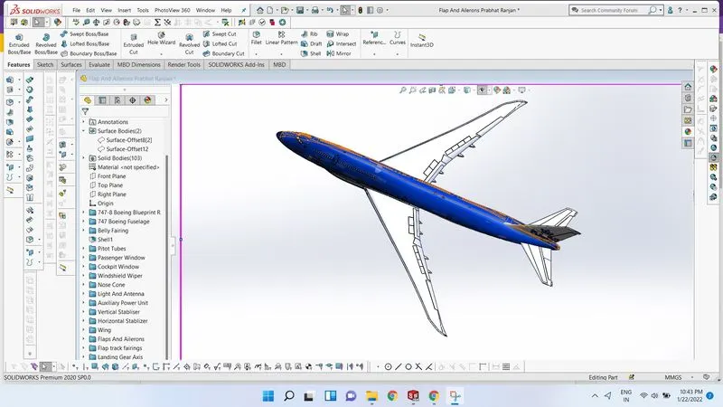
15 Landing Gear Axis
Landing gear axis is the axis in which base gear axis is assembled.During landing and take off aeroplane attain very high velocity so it has wheel which is connect with landing gear base.landing gear axis provide axial motion of landing gear base at time of landing and take off .
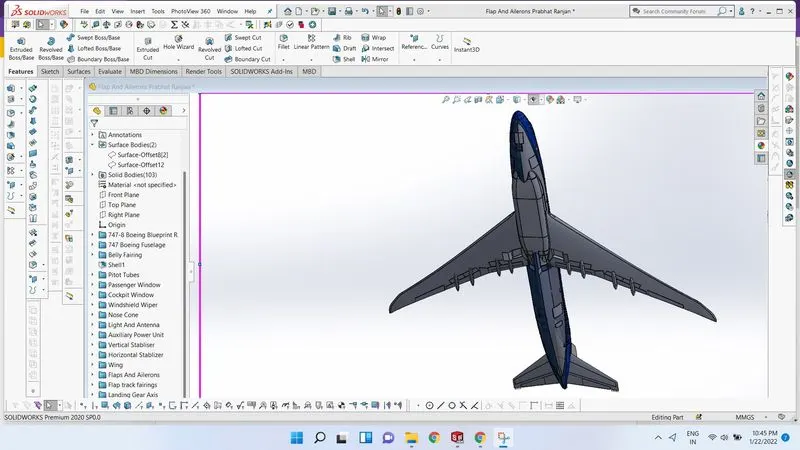
16Landing Gear Hatcches Open
Landing gear hatch open is like a hole in which wheel and landing gear base goes into body when plane flies in the sky .At time of flying landing gear base and wheel not required so it goes into body and comes out when plane land.
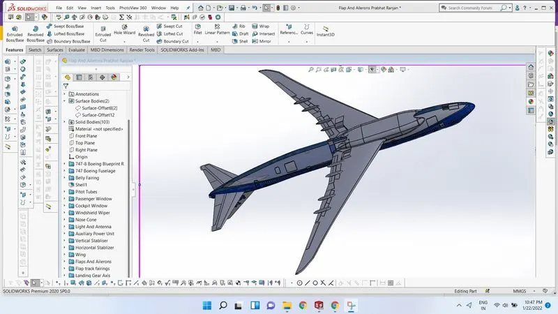
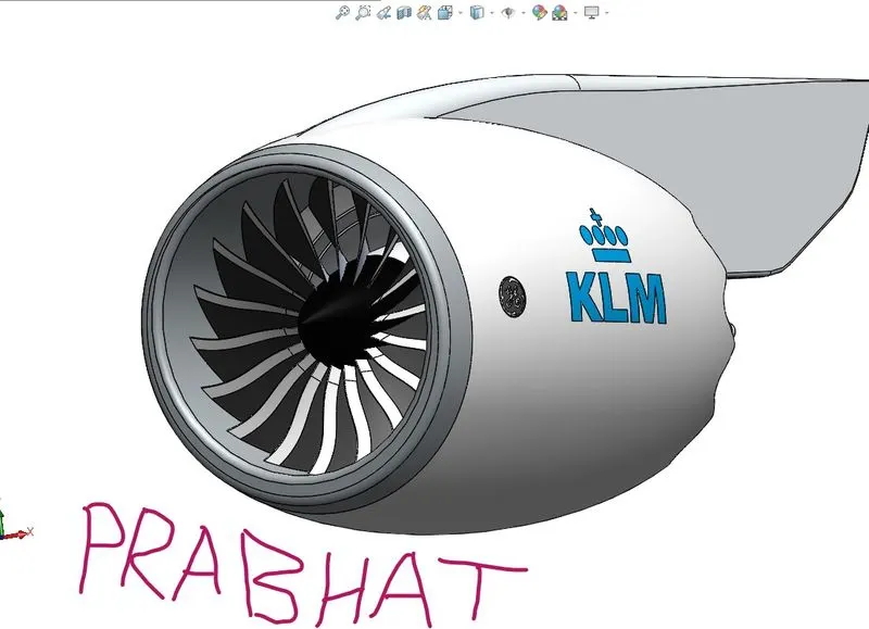
17 Engine-
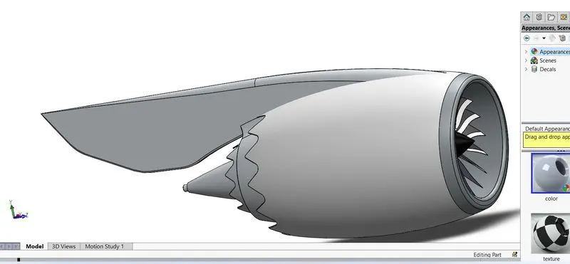
Engine of aircraft often referred to as an aero engine.The propulsion system of plane is done by engine .Engine may be piston type of gas type ,most of plane has turboprop engine which works on joule cycle.main component of engine is compressor ,turbine and nozzle.combustion of fuel takes place either on constant pressure and or constant volume.
Engine of boeing 747-8 is very power full it produces 66,500lb of thrust
 .
.
18 Livery-
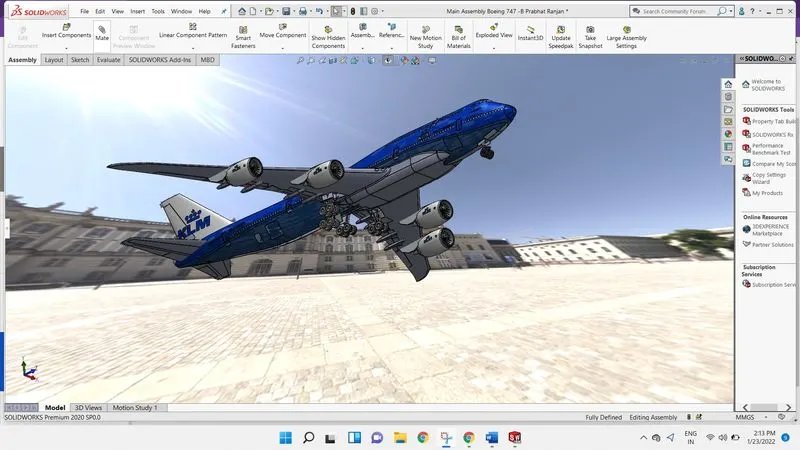
An air craft livery is a set of comprehensive insignia composing colour,graphics,and typographical identifiers which operators airlines (government,military,airforce,personal,or any privates group)apply to their aircraft.
Sub- Assemblies
1 Nose Gear Assembly-
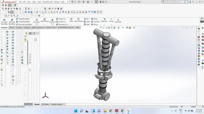
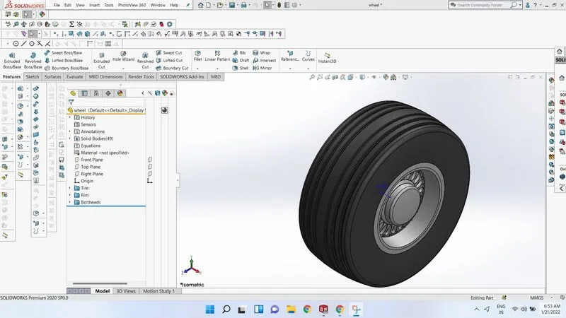
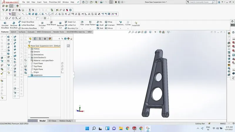
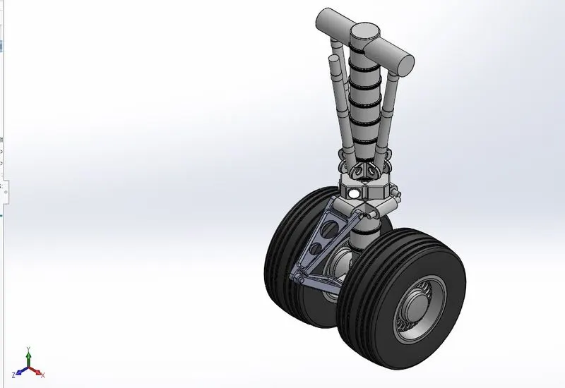
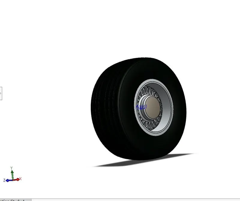
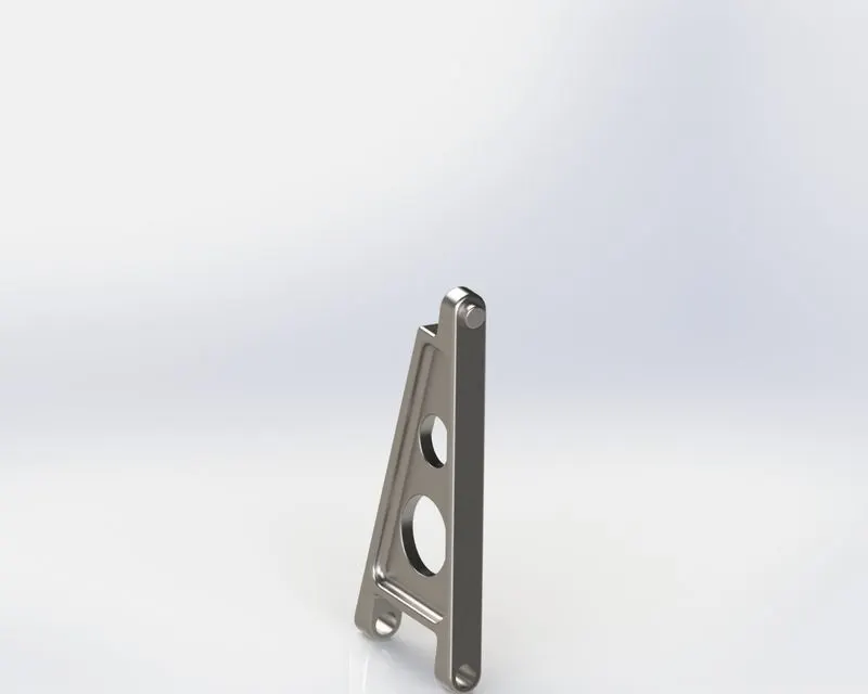
Nose gear has parts like Nose Gear base ,Suspension arm and wheels. The parts are initially modeled and the parts are inserted into the assembly environment and the sub assembly is created for nose gear .In Boeing 747-8 one nose gear assembled is used . There are two wheel in the nose gear assembly.
2 Main Gear Assembly
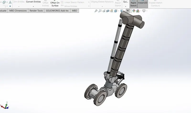
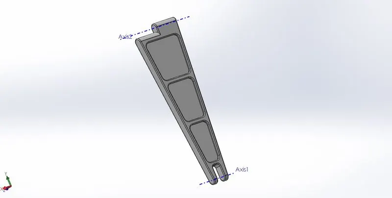
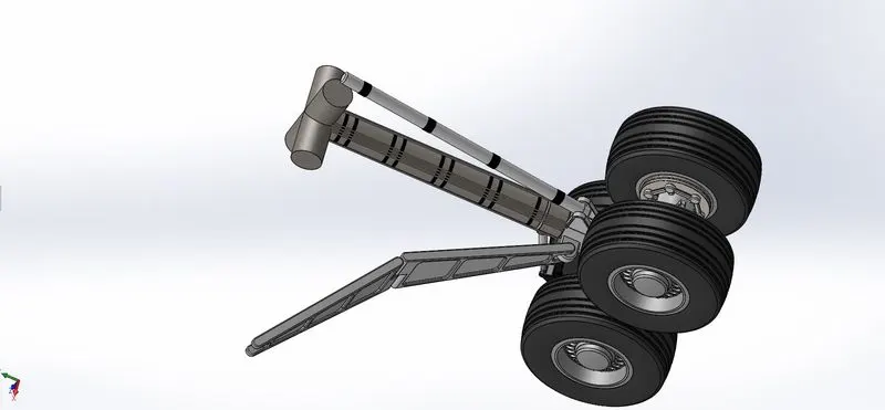
The main gear assembly consist of main gear base ,suspension arm ,wheels .It has four wheels as shown in below fig.All the parts are sub assembled and finally assumbled with main body .
Boeing 747-8 Assembly
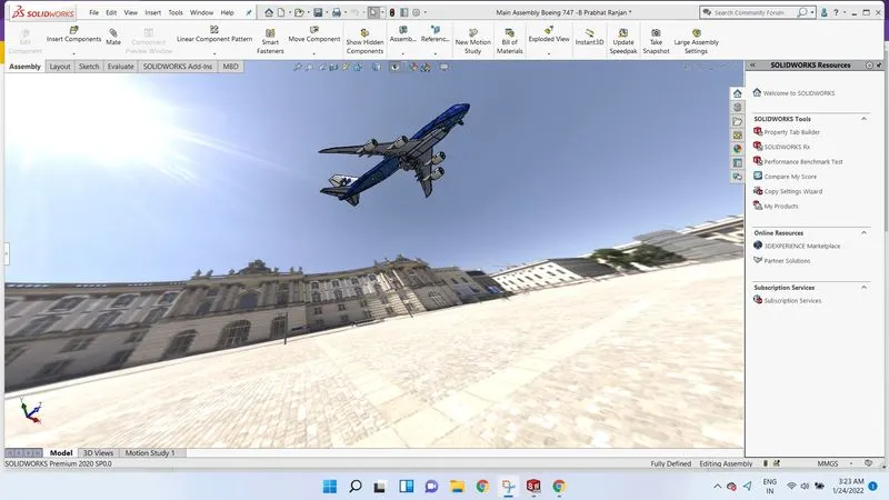
After completing the livery part the main body (Fuselage)are inserted into assembly environment .Then the engine ,Nose gear assembly ,and main gear assembly are inserted one by one and assembled them at their respective position
Steps-
. Insert all sub assembled and main body.
. make coincident relation of planes of main body(Fuselage) and planes of assembly planes.
. All part like engine ,nose gear assembly and main gear assembly first make cocentric relation with axis of body and axis of parts.
.After that give certain dimension.
.Make angular mate.
.Make gear mate between nose gear and main gear .
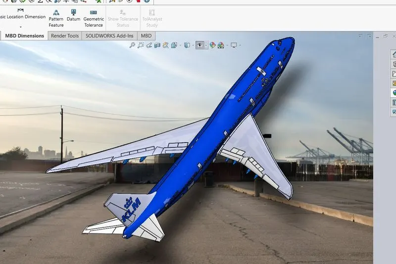
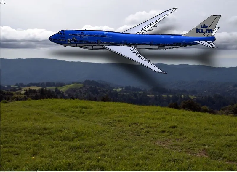
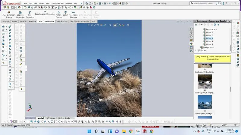
At last solidworks gives very important tool called Render tool.In Render tool we can produce realistic photo of our design that affecinate everyone,and makes your image 360views.some of the rendered photo is shown below.
Conclusion-
All parts of the Boeing 747-8 are modeled and assembled with the main body successfully. The final result is as same as the original Boeing 474-8 in every aspect.
Thank You !
Prabhat Ranjan