Photo Realistic Rendering
MODELLING OF AMERICAN CHOPPER ON SOLIDWORKS
Introduction
In this project, we learnt about designing an American Chopper using Solidworks. At first, we learn about each command and apply it to create each part. With the help of the blueprint, we get the idea about sketching and dimensioning the parts. After designing the parts, we study about assembling each part to create the American Chopper. We also get to study about rendering the model using Photo view 360 and Solidworks Visualize. While rendering we get to know about applying decals, lights and cameras.
The parts we designed for creating the American Chopper are mentioned below:
- Chassis
- Engine with exhaust system
- Front Wheel
- Rear Wheel
- Front Fork
- Front
- Rear Fender
- Oil Tank
- Gas Tank
- Chain
- Transmission Belt
- Kickstand
- Pedal
Objective
- To learn the commands in Solidworks
- To design parts with the use of blueprints
- To assemble the parts
- To render the American Chopper on PhotoView 360 and Solidworks Visualize.
Design Approach
There are two types of design approach for modelling in Solidworks
- Bottom Up Approach: You first design and model parts, then insert them into an assembly and use mates to position the parts. To change the parts, you must edit them individually. These changes are then seen in the assembly.
- Top Down Approach: One or more features of a part are defined by something in an assembly, such as a layout sketch or the geometry of another part. The design intent comes from the top, which is the assembly, and moves down to the parts.
Here we have used Bottom Up Approach because it is the simplest method for creating an assembly.
Here are the some of the commands which we used to complete this project model:
- Extrude and Extrude-Cut
- Revolve and Revolve-Cut
- Swept and Swept-Cut
- Lofted Base/Boss
- Fillet
- Chamfer
- Linear Pattern
- Circular pattern
- Curve Driven Pattern
- Mirror ( in Part and Assembly)
- Shell
- Reference Geometry (Plane & Axis)
- Curve (Project & Composite)
- Dome
- Split
- Combine
- Boundary Surface
- Knit Surface
- Mates
- Coincident
- Concentric
- Tangent
- Parallel
- Perpendicular
- Distance
- Angle
- Width
- LImit Angle
Now let us see how these commands or features helped us in creating the parts and assembly of American Chopper.
-
Transmission Belt
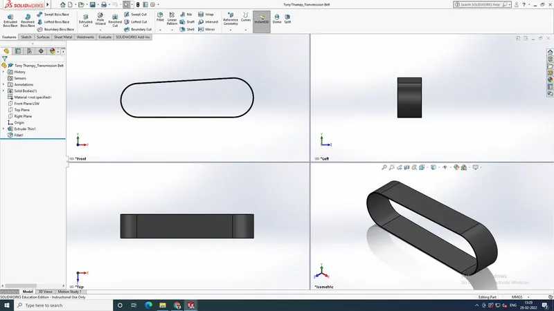
This part is all based on its sketch. It was easy to model this part.
The features used are:
- Sketch
- Extrude
- Fillet
Appearance: Matte Rubber
-
Kickstand
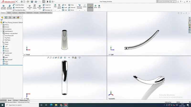
We have created an additional plane to create an elliptical profile. Thus created the base structure using loft and some cuts were done to acquire the model. And extrusions were made between the faces, Finally applied fillets.
Appearance: Chromium Plate
-
Front Fender
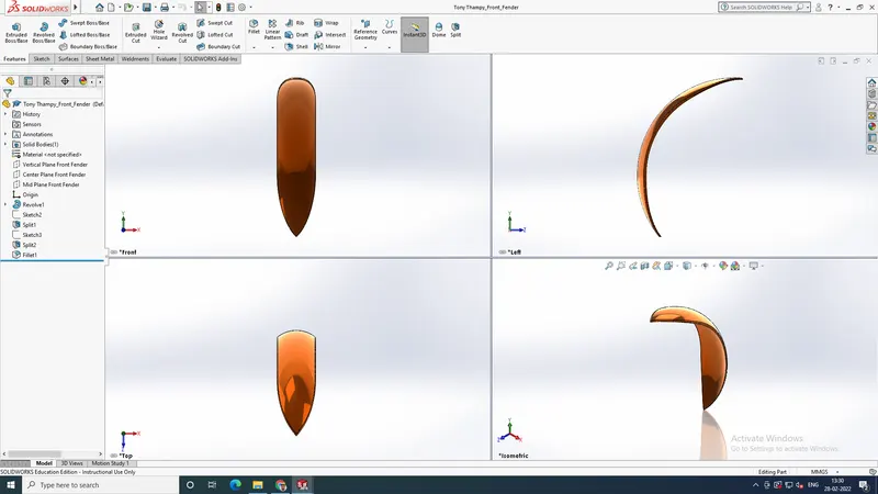
We applied a revolve feature to the sketch and applied proper dimensions along with it. We used spline sketches and split features to acquire the end shapes of the part. Finally applied fillets also.
Appearance: Sienna
-
Rear Fender
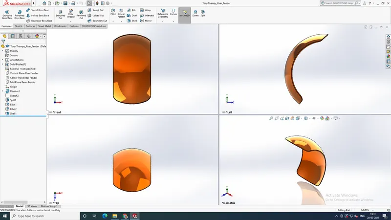
It was the same as that of the way creating the front fender. Only the dimension values and sketches are different. Same features are used and a shell feature is used in the inner face of the rear fender.
Appearance: Sienna
-
Oil Tank
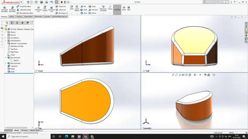
Two different sketches were made on the midplane and top plane. Both the sketches were extruded without applying merge results. After we got extracted the common part of two bodies using combine feature. Thus we got the base structure and then applied shell and fillets on the part.
Appearance: Sienna
-
Chain
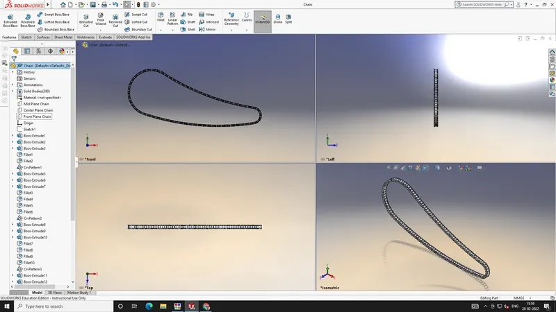
The base sketch path of the chain consists of two arcs and two lines which are tangent. Then we draw the sketch blocks and pins and extrude it and we have applied four curve driven patterns to the extruded feature, giving the path as one by one entities of the sketch path. It is to be noted that we have drawn sketch blocks again at the end of each pattern. After the patterns, we applied a mirror feature to each body with respect to the midplane.
Appearance: Chromium Plate
-
Pedal
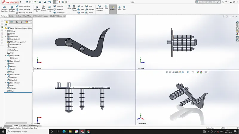
The base sketch which consists of lines, arcs, and splines were extruded and circular extrusions are made on the extruded feature. Features like linear patterns, chamfer and fillets are also used in modifying the circular extrusions.
Appearance: Chromium Plate
-
Front Wheel
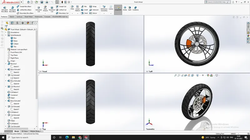
Revolve and Circular pattern features are the main features used to create the front wheel. The part is separated into four bodies. Tyre, Rim, Rotor and Caliper. Different features were used to create the part.
Appearance:
- Tyre: Matte Rubber
- Rim: Chromium Plate
- Rotor: Carbon Steel
- Caliper: Sienna
The Features are :
- Sketch
- Revolve
- Cut Extrude
- Revolve Cut
- Circular Pattern
- Chamfer
- Fillet
-
Rear Wheel
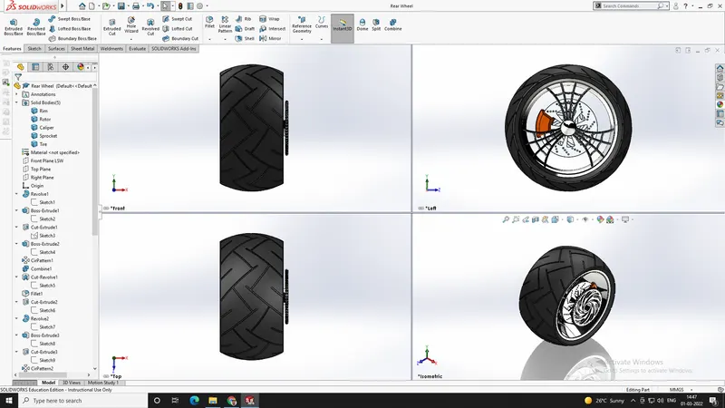
Same method is used to create the front wheel, but the dimensions are different. Same appearance is also given. An additional extrusion is also done for connecting the chain part in assembly.
-
Front Fork
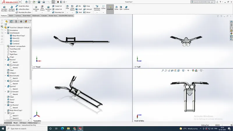
Though the front fork is symmetrical, we tried to create one of the sections. After that we mirrored the section to create the whole part. Lot of features were used to create the part. Projected Curves were also used to create the handle portions.
Features used are:
- Sketch
- Revolve
- Fillet
- Linear Pattern
- Extrude Cut
- Dome
- Curve
- Sweep
- Reference Plane
- Mirror
- Combine
Appearance: Chromium Plate
-
Chassis
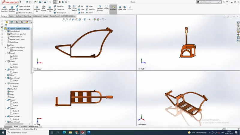
We used the blueprint image to create the chassis. Curve features were used to create the exact shape of the chassis. Additional planes are also used to help in creating the model.
Appearance: Sienna
Features used:
- Curves
- Mirror
- Boss Extrude
- Chamfer
- Dome
- Split
- Revolve
- Fillet
- Combine
-
Engine
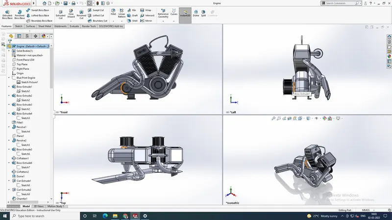
It took a lot of time to create the engine. Most of the commands we studied were used in creating the engine. Projected curves are used to create the exhaust portion. We have used the blueprint to create the exact shape of the engine.
Appearance: Chromium Plate
Features used are:
- Sketch
- Extrude
- Fillet
- Revolve
- Dome
- Circular Pattern
- Linear Pattern
- Mirror
- Cut Extrude
- Combine
- Projected Curve
- Composite Curve
- Split
-
Gas Tank
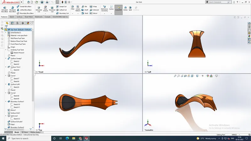
To create the base shape of the gas tank, we have used the blueprint and surface modelling features. The gas tank is symmetrical, so we created the half of the gas tank and used a mirror feature to create the whole. The surfaces were combined using Knit Surface features.
Features used are:
- Sketch
- Surface Sweep
- Trim Surface
- Boundary Surface
- Surface Loft
- Curve
- Mirror
- Knit Surface
- Extrude Surface
- Fillet
- Cut Extrude
- Shell
ASSEMBLY OF AMERICAN CHOPPER
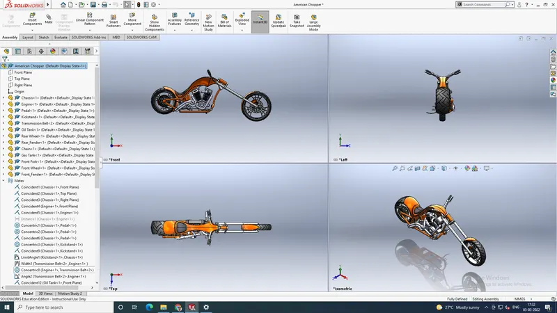
We have created all the parts and imported them to the assembly. First of all, we fixed the chassis part and with reference to the chassis, we connected all the other parts using mates. Different types of mates were used for this assembly. We have also used the planes of chassis as reference to align other parts. Some of the parts were modified during the assembly to make it perfect according to requirement.
RENDERING
The term rendering comes from the graphic world where a rendering is an artistic drawing of what a new structure would look like. In Computer Aided Design (CAD), a rendering is a particular view of a realistic image. By doing a rendering of the chopper we get the idea of how it will look into the environment.
- Rendering in PhotoView 360:
It can be enabled from the SOLIDWORKS Add-Ins menu. PhotoView 360 runs directly inside of SOLIDWORKS and does not require users to leave the application to set up a rendering. View setup is simple, since it is done entirely in SOLIDWORKS. Part and material appearances are also added directly within SOLIDWORKS. Users can add various lights and backgrounds to the scene within the SOLIDWORKS graphics area.
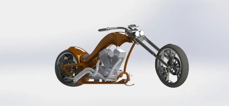
- Rendering in Solidworks Visualize:
SOLIDWORKS Visualize Standard takes it to the next level. Just like PhotoView 360, it is included with a license of SOLIDWORKS Professional or Premium for users who are currently subscribed. It is a standalone application that can import several CAD formats. This allows the application to be run separately from SOLIDWORKS without consuming a SOLIDWORKS license. This can be a great solution for organizations where the rendering might be created by another team, such as the marketing department. SOLIDWORKS parts and assemblies can also be monitored for any design changes.
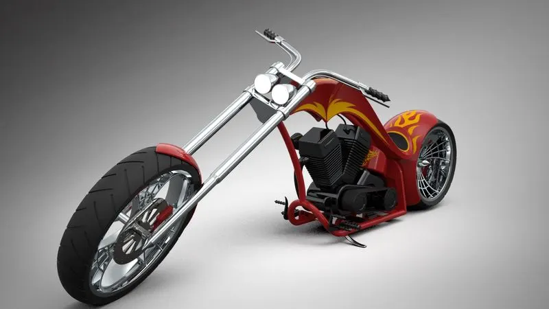
This allows renderings to be set up earlier in the design process, without concerns that the work will need to be repeated once the design is updated. SOLIDWORKS Visualize is a fully capable ray tracing rendering application. Reflections and refractions of light will have a higher quality and more photo-realistic appearance once the rendering has been calculated. The calculations can also be done on either the CPU or the GPU when using a supported graphics card. Below is an example of a similar rendering that was created in SOLIDWORKS Visualize Standard. The lighting and textures look more realistic, and it leads to a higher quality image.
DECALS
A decal is a 2D image applied to a model. You can use decals to apply warning or instruction labels to models. You can also use decals to create model details that you can effectively represent with an image instead of with the model geometry, such as a car grill or a picture frame.
You can view and apply decals in SOLIDWORKS. You can view decals in eDrawings and PhotoView 360.
CAMERAS
We can add cameras to model documents and view the model from the camera perspective.
You can:
- Specify the positions of targets and cameras.
- Attach cameras to objects and sketch entities. The camera can then show motion or move with the entity.
- Place cameras inside models.
- Roll cameras to specified angles.
- Control properties of field of view and depth of field.
- Use cameras in animations.
SCENES
Scenes provide a visual backdrop behind a model. In SOLIDWORKS, they provide reflections on the model. With PhotoView 360 added in, scenes provide a realistic light source, including illumination and reflections, requiring less manipulation of lighting. The objects and lights in a scene can form reflections on the model and can cast shadows on the floor.
A scene consists of the following:
- A spherical environment based on a preset scene or image you select is mapped around the model.
- A 2D background that can be a single colour, a gradient of colour, or an image you select. Although partially obscured by the background, elements of the environment are reflected in the model. You can also turn off the background and show the spherical environment instead.
- A 2D floor on which you can see shadows and reflections. You can change the distance of the model from the floor.
LIGHTING
We can adjust the direction, intensity, and colour of light in the shaded view of a model. You can add light sources of various types, and modify their characteristics to illuminate the model as needed.
We can change the appearance of the model to enhance or reduce the effect of lighting properties.
There are several types of light source:
- Ambient light: Illuminates the model evenly from all directions. In a room with white walls, the level of ambient light is high, because the light reflects off the walls and other objects.
- Directional light: Comes from a source that is infinitely far away from the model. It is a columned light source consisting of parallel rays from a single direction, like the sun.
- Point light: Comes from a very small light source located at a specific coordinate in the model space. This type of light source emits light in all directions. The effect is like a tiny light bulb floating in space.
- Spot light: Comes from a restricted, focused light with a cone-shaped beam that is brightest at its centre. A spotlight can be aimed at a specific area of the model. You can adjust the position and distance of the light source relative to the model, and you can adjust the angle through which the beam spreads.
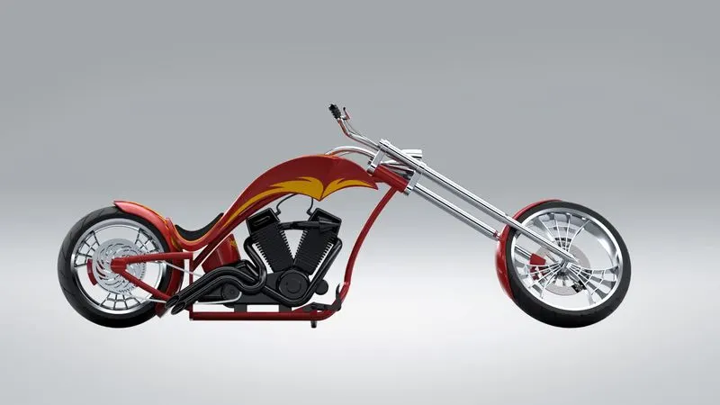
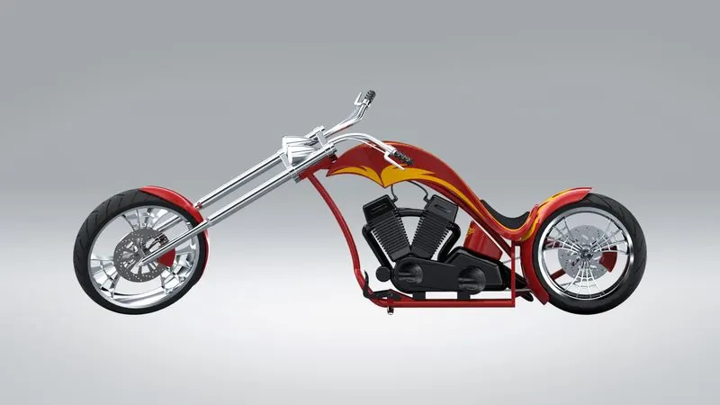
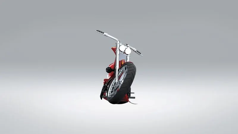
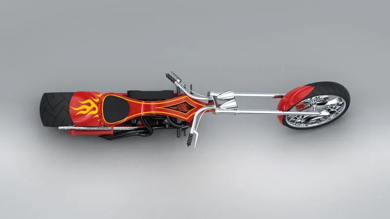
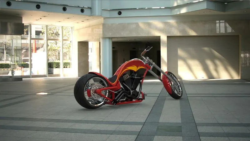
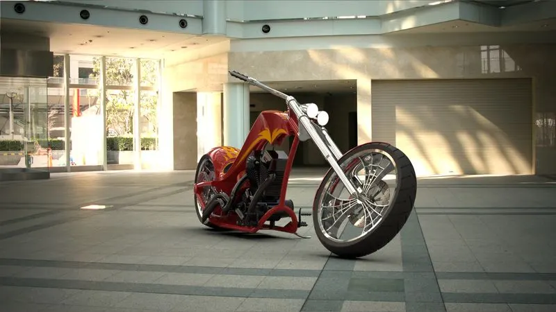
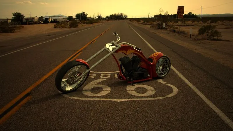
RENDERED IMAGES OF AMERICAN CHOPPER
Conclusion
The project on American Chopper helped us understand the different portions of solidworks such as Solid modelling, Surface modelling, Assembly Modelling, Rendering etc. It helped us to have knowledge on different commands. It helped us to get the idea that only with a proper blueprint, we can create the model using our own dimensions.