Aston Martin ONE-77 Challenge-11 (Project)
SURFACE MODELLING OF ASTON MARTIN ONE 77 USING SOLIDWORKS
Objective
- To learn the commands in Solidworks
- To design surfaces with the use of blueprints
- To assemble the parts
- To render the Aston Martin on PhotoView 360 and Solidworks Visualize
Introduction
In this project, we learnt about designing an Aston Martin One-77 using Solidworks. At first, we learn about each command and apply it to create each part. With the help of the blueprint, we get the idea about sketching and dimensioning the parts. After designing the parts, we study about assembling each part to create the whole Aston Martin One-77
The parts we designed for creating the Aston Martin One-77 are mentioned below:
- Main Body
- Door
- Hood
- Grilles
- Lights
- Rear Bumper
- Windshield
- Side Window
- Rear Window
- Disc
- Caliper
- Rim (Front & Rear)
- Tire (Front & Rear)
- Emblem
Design Approach
There are two types of design approach for modelling in Solidworks
- Bottom Up Approach: You first design and model parts, then insert them into an assembly and use mates to position the parts. To change the parts, you must edit them individually. These changes are then seen in the assembly.
- Top Down Approach: One or more features of a part are defined by something in an assembly, such as a layout sketch or the geometry of another part. The design intent comes from the top, which is the assembly, and moves down to the parts.
Here we have used Bottom Up Approach because it is the simplest method for creating an assembly.
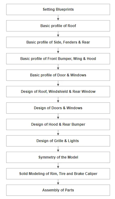
Here are the some of the commands which we used to complete this project model:
- Extrude and Extrude-Cut
-
Extrude tool is used to extend a sketched profile in one or two directions as either a thin feature or a solid feature. An extrude operation can either add material to a part (in a base or boss) or remove material from a part.
- Revolve and Revolve-Cut
-
To create a revolve feature: Create a sketch that contains one or more profiles and a centerline, line, or edge to use as the axis around which the feature revolves. Click one of the following revolve tools: Revolved Boss/Base (Features toolbar) or Insert > Boss/Base > Revolve.
- Swept and Swept-Cut
-
SWEEP is the one feature in Solidworks that helps sweep a closed profile along a closed or open path.
- Fillet
-
Fillet/Round creates a rounded internal or external face on the part. You can fillet all edges of a face, selected sets of faces, selected edges, or edge loops.
- Chamfer
-
The chamfer tool creates a bevelled feature on selected edges, faces, or a vertex.
- Linear Pattern
-
Use linear patterns to create multiple instances of one or more features that you can space uniformly along one or two linear paths. Create one or more features to replicate.
- Circular pattern
-
Pattern instances inherit the feature colour of the original feature when the pattern is based on one feature and colour of the pattern or any faces on any pattern instances have not been changed.
- Mirror
-
Mirroring is another way that SolidWorks can create a “copy” of an existing object. Additionally, you must choose a plane to mirror parts. In most cases, you will have to create your own plane to have the mirror done the way you need.
- Split Line
-
This command is generally useful when we need to create additional faces on a model without altering the geometry. To create a split line, we can either use a sketch, plane, or another solid body in the vicinity.
- Shell
-
The shell tool hollows out a part, leaves open the faces you select, and creates thin-walled features on the remaining faces. If you do not select any face on the model, you can shell a solid part, creating a closed, hollow model. You can also shell a model using multiple thicknesses.
- Reference Geometry (Plane & Axis)
-
Reference geometry defines the shape or form of a surface or a solid. Reference geometry includes items such as planes, axes, coordinate systems, and points. You can use reference geometry in the creation of several kinds of features.
- Split
-
The split feature is an extremely useful tool when designing using multi body part techniques in SOLIDWORKS.
- Combine
-
In a multibody part, you can combine multiple solid bodies to create a single-bodied part or another multibody part. You can add or subtract bodies, or keep material that is common to the selected bodies.
- Extrude Surface
- Revolve Surface
- Sweep Surface
- Offset Surface
-
The offset surface tool is useful way of creating a series of deposit or erosion contact surfaces from a reference mesh. The surface can be offset from the reference mesh by points or by a fixed distance, and additional options for offsetting to points can be adjusted once the surface has been created.
- Thicken
-
Creates a solid feature by thickening one or more adjacent surfaces.
- Boundary Surface
- Loft Surface
- Move/Copy BodyWe can change the location of the body from one place to another
- Delete Body
We can delete the bodies whenever we want
- Mates
-
Mates create geometric relationships between assembly components. As you add mates, you define the allowable directions of linear or rotational motion of the components. You can move a component within its degrees of freedom, visualizing the assembly's behavior.
Now let us see how these commands or features helped us in creating the parts and assembly of One77
1. BLUEPRINTS
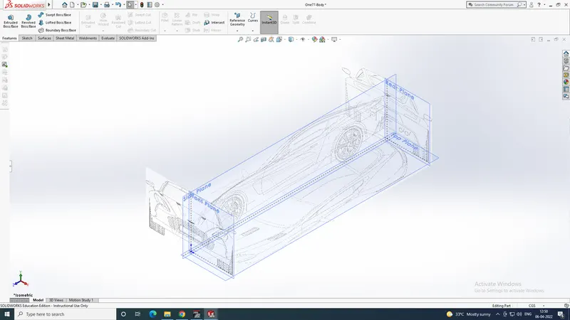
The blueprints were inserted to the corresponding planes. These blueprints helped in the modeling of the surface of each parts of the One77.
NOTE: In this project, we created all the basic profiles of each parts in the main body part and after that we splited them and converted into different parts for further modification.
2. BASIC PROFILES OF EACH PART
- Roof
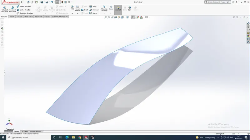
The features used are:
- Projected Curve
- Sketch
- Boundary Surface
- Side
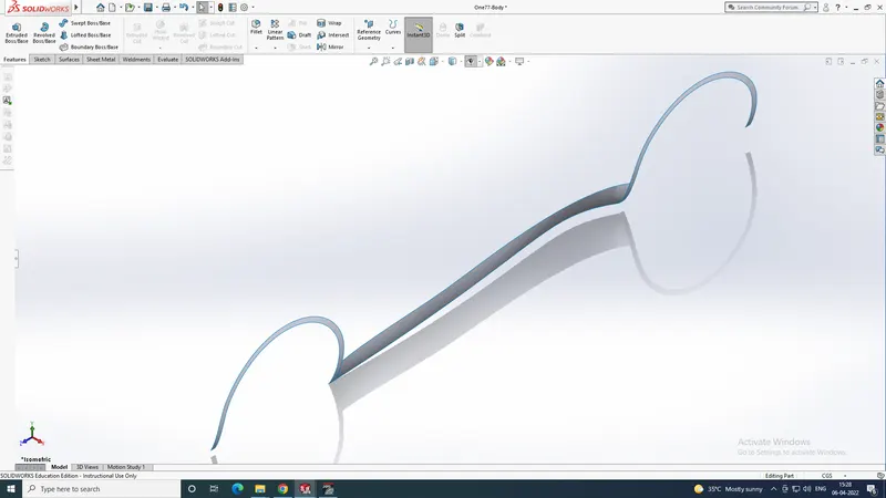
The features used are:
- Projected Curve
- Sketch
- Boundary Surface
- Surface Trim
- Surface Extrude
- Fender
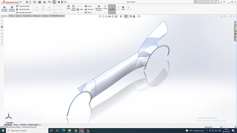
The features used are:
- Sketch
- Projected Curve
- Boundary Surface
- Surface Fill
- Trim Surface
- Delete Face
- Knit Surface
- Rear Bumper
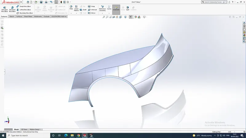
The features used are:
- Sketch
- Projected Curve
- Boundary Surface
- Fillet
- Surface Fill
- Trim Surface
- Offset Surface
- Delete Face
- Ruled Surface
- Knit Surface
- Front Bumper
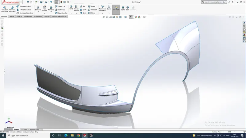
The Features used are:
- Sketch
- Projected Curve
- Boundary Surface
- Fillet
- Surface Fill
- Trim Surface
- Offset Surface
- Delete Face
- Ruled Surface
- Knit Surface
- Move/Copy Body
- Split
- Thicken
- Hood
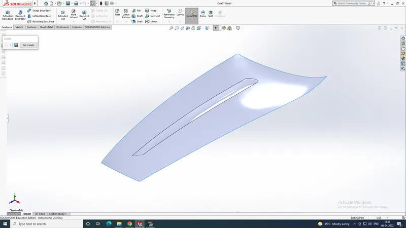
The features used are:
- Sketch
- Projected Curve
- Boundary Surface
- Surface Fill
- Trim Surface
- Knit Surface
- Split
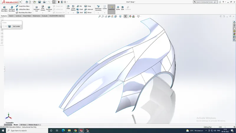
- Windows
 \
\
The features used are:
- Sketch
- Projected Curve
- Boundary Surface
- Fillet
- Surface Fill
- Trim Surface
- Offset Surface
- Knit Surface
- Door
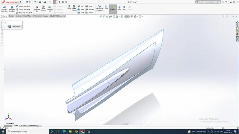
The features used are:
- Sketch
- Projected Curve
- Boundary Surface
- Fillet
- Surface Fill
- Trim Surface
- Offset Surface
- Delete Face
- Knit Surface
- Delete Body
- Thicken
- Mirror
- Front Wing
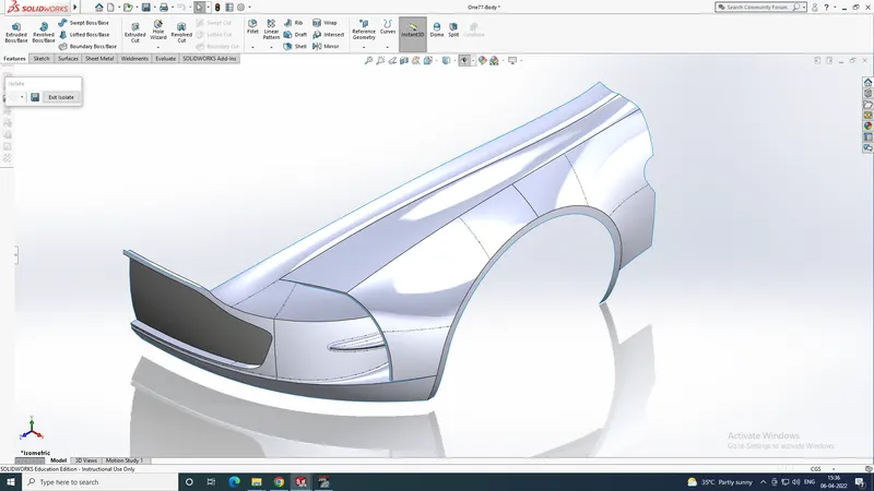
The features used are:
- Sketch
- Projected Curve
- Boundary Surface
- Surface Fill
- Trim Surface
- Offset Surface
- Knit Surface
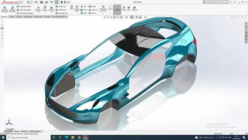
- THE MAIN BODY BEFORE SPLITING
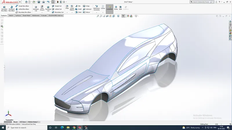
NOTE: After this, each surface is splitted and converted to each part.
2. HOOD
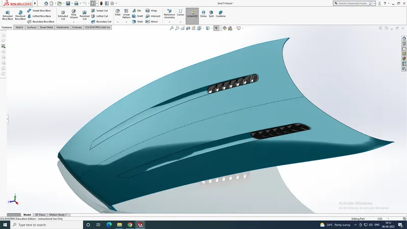
The features used after spliting are:
- Split
- Extrude & Cut Extrude
- Move/Copy Body
- Cut with Surface
- Linear Pattern
- Mirror
3. DOORS
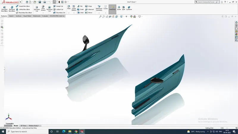
The features used after spliting are:
- Split
- Extrude & Cut Extrude
- Move/Copy Body
- Cut with Surface
- Linear Pattern
- Mirror
- Fillet
- Delete Face
- Loft Surface
- Boundary Surface
- Knit Surface
4. GRILLES
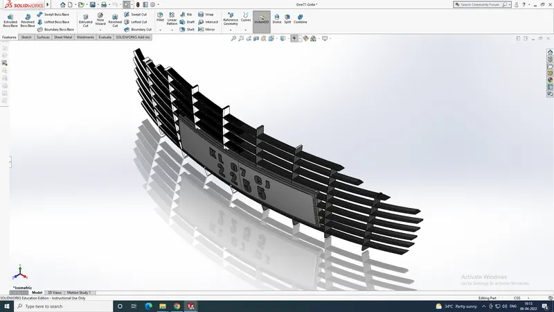
The features used after spliting are:
- Split
- Extrude & Cut Extrude
- Move/Copy Body
- Cut with Surface
- Linear Pattern
- Mirror
- Fillet
- Delete Face
- Loft Surface
- Boundary Surface
- Knit Surface
- Offset Surface
- Combine
5. LIGHTS
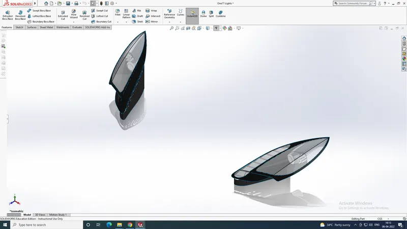
The features used after spliting are:
- Split
- Extrude & Cut Extrude
- Move/Copy Body
- Cut with Surface
- Mirror
- Fillet
- Delete Face
- Loft Surface
- Boundary Surface
- Knit Surface
- Offset Surface
- Combine
- Fill Surface
- Revolve
- Intersect
- Curve Driven Pattern
6. WINDSHIELD
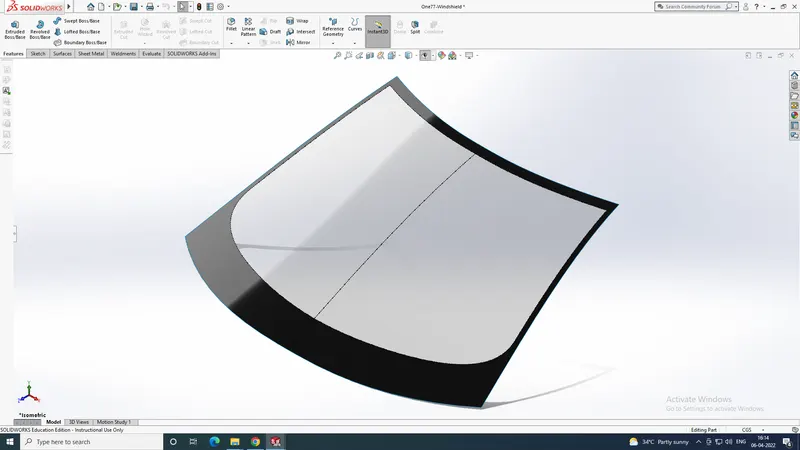
The features used after spliting are:
- Split Line
- Mirror
- Knit Surface
7. SIDE WINDOWS
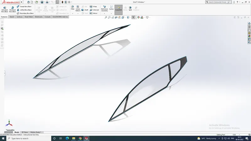
The features used after spliting are:
- Split line
- Delete Face
- Thicken
- Mirror
- Offset Surface
8. REAR WINDOW
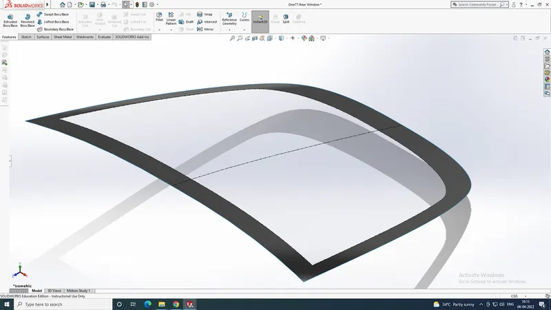
The features used after spliting are:
- Split Line
- Knit Surface
- Mirror
9. REAR BUMPER
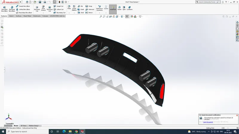
The features used after spliting are:
- Split
- Extrude & Cut Extrude
- Move/Copy Body
- Cut with Surface
- Mirror
- Fillet
- Delete Face
- Loft Surface
- Boundary Surface
- Knit Surface
- Offset Surface
- Shell
- Ruled Surface
10. CALIPER
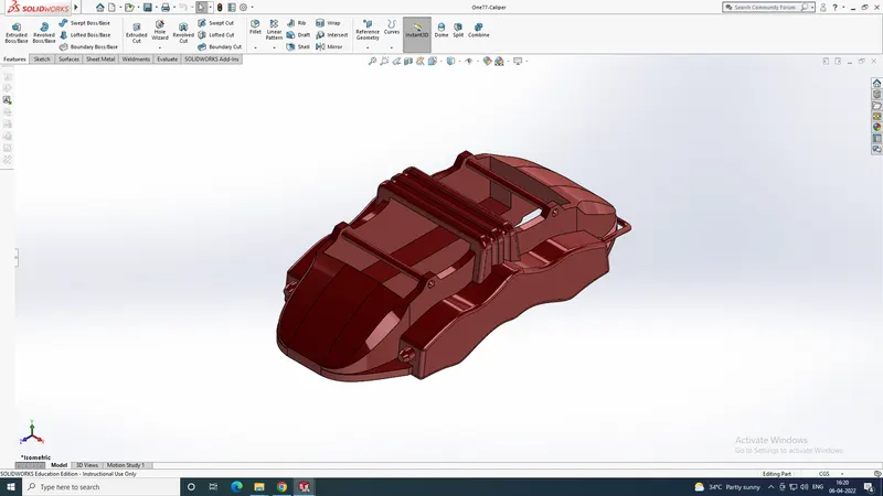
The features used are:
- Split
- Extrude & Cut Extrude
- Move/Copy Body
- Cut with Surface
- Mirror
- Fillet
- Loft Surface
- Combine
- Chamfer
- Delete Body
11. DISC
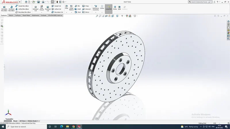
The features used after spliting are:
- Revolve
- Circular Pattern
- Curve driven Pattern
- Combine
12. FRONT & REAR RIM
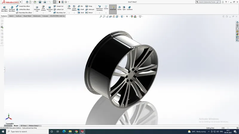
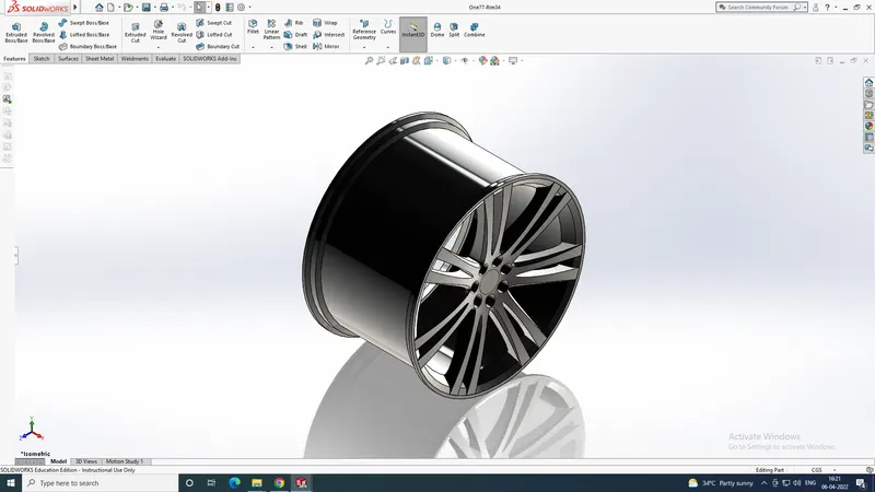
The only difference with front and rear rim is the dimension. The front rim has a width of 27cm and rear of 34cm. All the other features are same.
The features used are:
- Revolve
- Cut Extrude
- Surface loft
- Surface Cut
- Circular Pattern
- Combine
- Move/Copy Body
13. FRONT & REAR TIRE
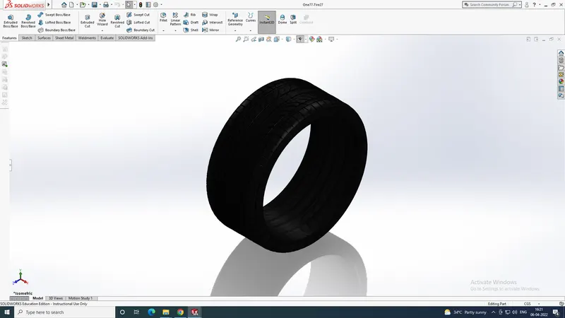
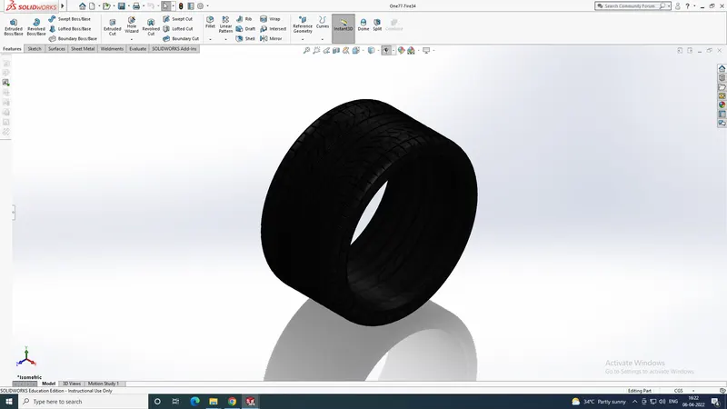
The only difference with front and rear tire is the dimension. The front tire has a width of 27cm and rear of 34cm. All the other features are same.
The features used are:
- Revolve & Cut revolve
- Cut Extrude
- Cut Sweep
- Circular Pattern
- Combine
- Move/Copy Body
- Chamfer
- Mirror
14. EMBLEM
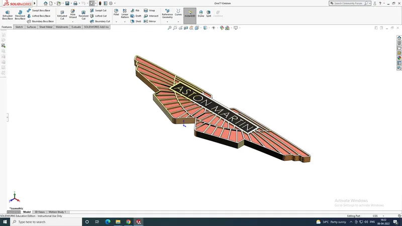
The features used are:
- Extrude & Cut Extrude
- Combine
- Mirror
15. MAIN BODY AFTER SPLITTING
ASSEMBLY
Before going to the main assembly, we created to three subassemblies.
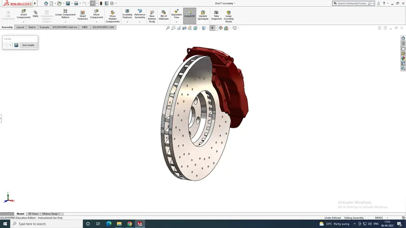
- BRAKE DISC ASSEMBLY: In this assembly, Caliper and Disc are used. Mates were used to give relation with the parts
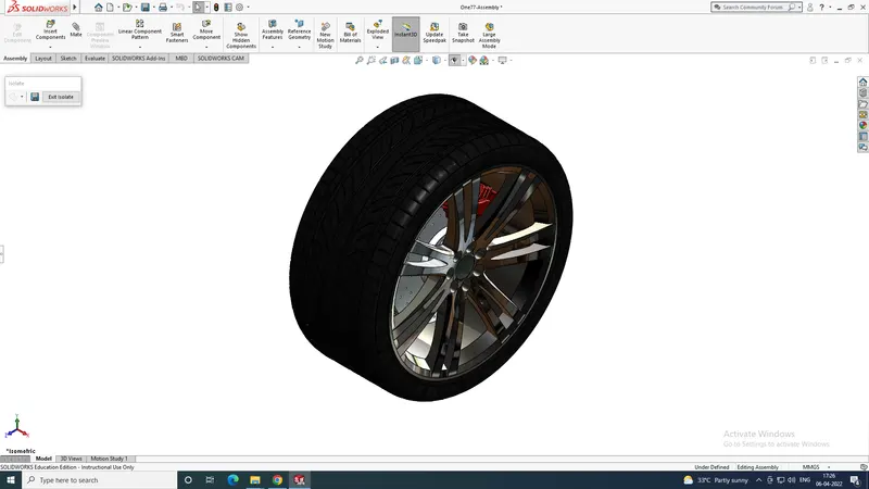
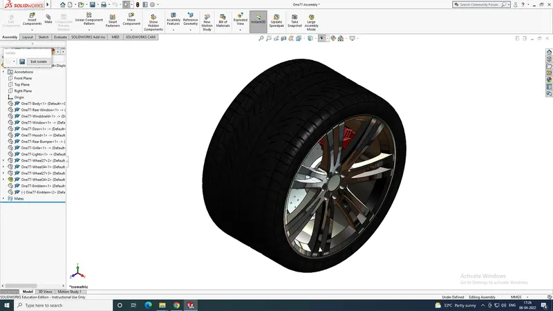
- FRONT WHEEL ASSEMBLY: In this assembly, Brake Disc Subassembly, the front rim and front tire are used. Mates were used to give relation with the parts
- REAR WHEEL ASSEMBLY: In this assembly, Brake Disc Subassembly, the rear rim and rear tire are used. Mates were used to give relation with the parts
- BRAKE DISC ASSEMBLY
- FRONT & REAR ASSEMBLY
THE MAIN ASSEMBLY
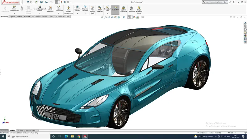
All the parts and sub-assemblies are added to the main assembly.
The mates used in the assembly are:
- Coincident
- Concentric
- Parallel
- Distance
- Width
- Angle
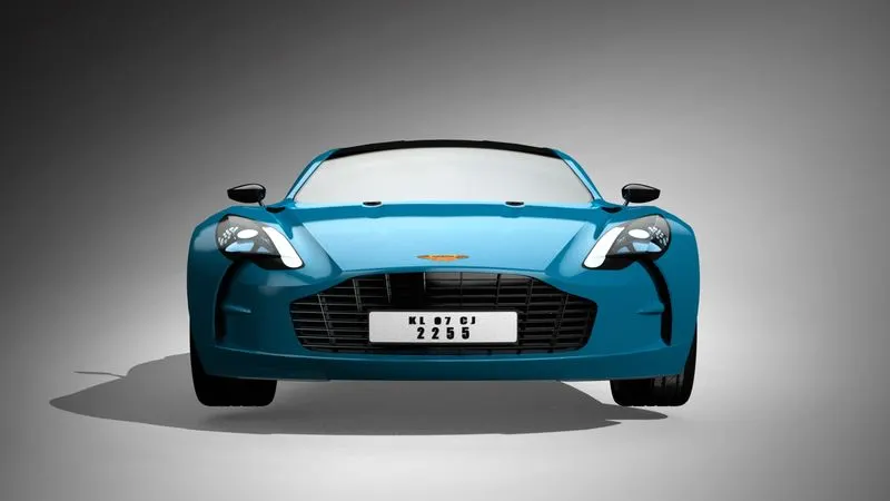
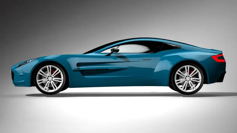
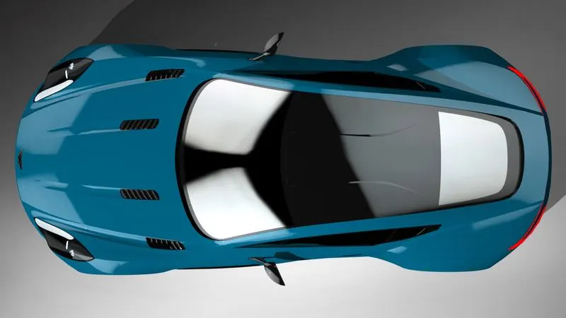
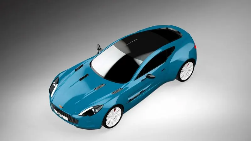
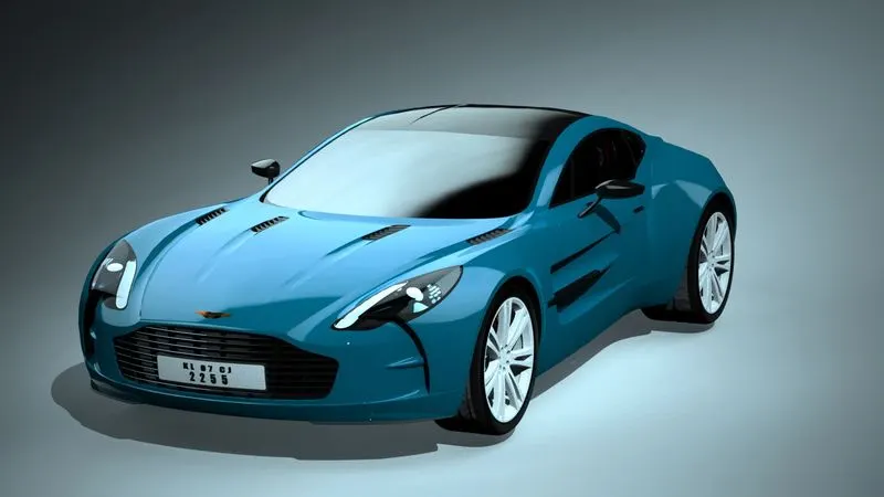
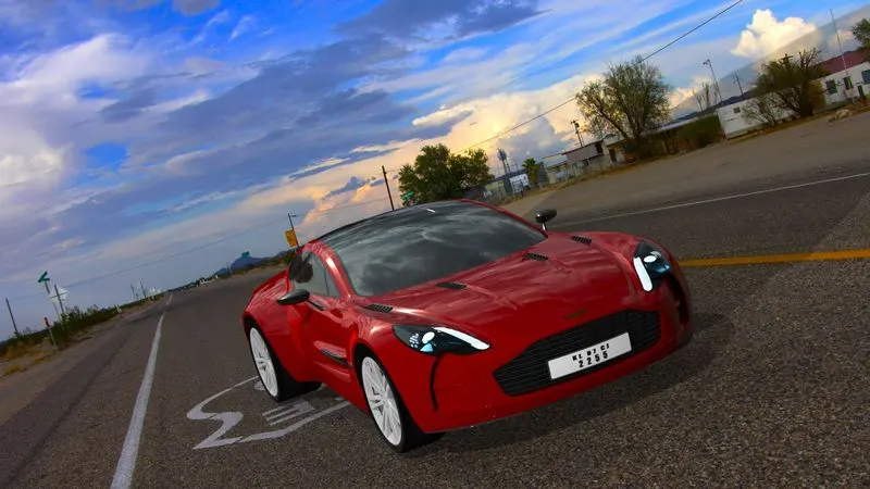
RENDERED IMAGES OF ASTON MARTIN ONE77


CONCLUSION
The project on Aston Martin One77 helped us understand the different portions of solidworks such as Solid modelling, Surface modelling, Assembly Modelling, Rendering etc. It helped us to have knowledge on different commands. It helped us to get the idea that only with a proper blueprint, we can create the model using our own dimensions.