Boeing-747 _ Final_Project
MODELLING OF BOEING 747-8 ON SOLIDWORKS
Objective
- To learn the commands in Solidworks
- To design parts with the use of blueprints
- To assemble the parts
- To render the Boeing 747-8 on PhotoView 360 and Solidworks Visualize.
Introduction
Boeing 747-8 is a wide body aircraft being the largest variant of the 747 is modelled using the Solidworks. The below data shows the specifications of the aircraft used for designing.
- Seats (3-class) - 410
- Range - 14310 km
- Length - 3m
- Wingspan - 4m
- Height (Overall) - 4m
- Height (nose to ground) - 8m
- Engine - GEnx-2B
Design Approach
There are two types of design approach for modelling in Solidworks
- Bottom Up Approach: You first design and model parts, then insert them into an assembly and use mates to position the parts. To change the parts, you must edit them individually. These changes are then seen in the assembly.
- Top Down Approach: One or more features of a part are defined by something in an assembly, such as a layout sketch or the geometry of another part. The design intent comes from the top, which is the assembly, and moves down to the parts.
Here we have used Bottom Up Approach because it is the simplest method for creating an assembly.
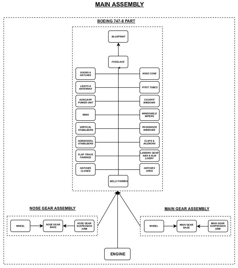
Boeing 747-8 part is the combination of the bodies mentioned in the above.
Here are the some of the commands which we used to complete this project model:
- Extrude and Extrude-Cut
Extrude tool is used to extend a sketched profile in one or two directions as either a thin feature or a solid feature. An extrude operation can either add material to a part (in a base or boss) or remove material from a part.
- Revolve and Revolve-Cut
To create a revolve feature: Create a sketch that contains one or more profiles and a centerline, line, or edge to use as the axis around which the feature revolves. Click one of the following revolve tools: Revolved Boss/Base (Features toolbar) or Insert > Boss/Base > Revolve.
- Swept and Swept-Cut
SWEEP is the one feature in Solidworks that helps sweep a closed profile along a closed or open path.
- Lofted Base/Boss
Loft creates a feature by making transitions between profiles. A loft can be a base, boss, cut, or surface. You create a loft using two or more profiles. Only the first, last, or first and last profiles can be points. All sketch entities, including guide curves and profiles, can be contained in a single 3D sketch.
- Fillet
Fillet/Round creates a rounded internal or external face on the part. You can fillet all edges of a face, selected sets of faces, selected edges, or edge loops.
- Chamfer
The chamfer tool creates a bevelled feature on selected edges, faces, or a vertex.
- Linear Pattern
Use linear patterns to create multiple instances of one or more features that you can space uniformly along one or two linear paths. Create one or more features to replicate.
- Circular pattern
Pattern instances inherit the feature colour of the original feature when the pattern is based on one feature and colour of the pattern or any faces on any pattern instances have not been changed.
- Mirror
Mirroring is another way that SolidWorks can create a “copy” of an existing object. Additionally, you must choose a plane to mirror parts. In most cases, you will have to create your own plane to have the mirror done the way you need.
- Split Line
This command is generally useful when we need to create additional faces on a model without altering the geometry. To create a split line, we can either use a sketch, plane, or another solid body in the vicinity.
- Shell
The shell tool hollows out a part, leaves open the faces you select, and creates thin-walled features on the remaining faces. If you do not select any face on the model, you can shell a solid part, creating a closed, hollow model. You can also shell a model using multiple thicknesses.
- Reference Geometry (Plane & Axis)
Reference geometry defines the shape or form of a surface or a solid. Reference geometry includes items such as planes, axes, coordinate systems, and points. You can use reference geometry in the creation of several kinds of features.
- Dome
- Split
The split feature is an extremely useful tool when designing using multi body part techniques in SOLIDWORKS.
- Combine
In a multibody part, you can combine multiple solid bodies to create a single-bodied part or another multibody part. You can add or subtract bodies, or keep material that is common to the selected bodies.
- Extrude Surface
- Revolve Surface
- Sweep Surface
- Offset Surface
The offset surface tool is useful way of creating a series of deposit or erosion contact surfaces from a reference mesh. The surface can be offset from the reference mesh by points or by a fixed distance, and additional options for offsetting to points can be adjusted once the surface has been created.
- Thicken
Creates a solid feature by thickening one or more adjacent surfaces.
- Mates
Mates create geometric relationships between assembly components. As you add mates, you define the allowable directions of linear or rotational motion of the components. You can move a component within its degrees of freedom, visualizing the assembly's behavior.
Now let us see how these commands or features helped us in creating the parts and assembly of Boeing 747-8.
-
Blueprint
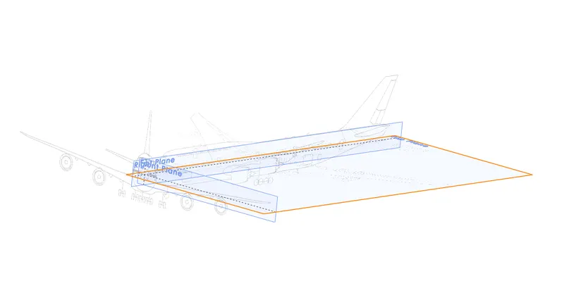
The blueprints are inserted into the respected planes as sketch entity.
-
Fuselage
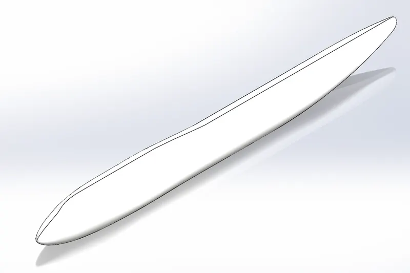
The main body section of the aircraft. It holds the crew, passengers and cargo.
The features used are:
- Sketch
- Reference Plane
- Surface Loft
- Mirror
- Thicken
-
Belly Fairing
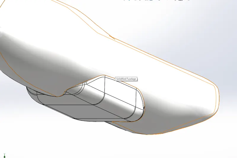
It is located under the fuselage between the main wings and covers the landing gears and holds additional cargo.
The features used are:
- Sketch
- Boss Extrude
- Fillet
- Combine
- Mirror
- Split
- Split Line
-
Nose Cone
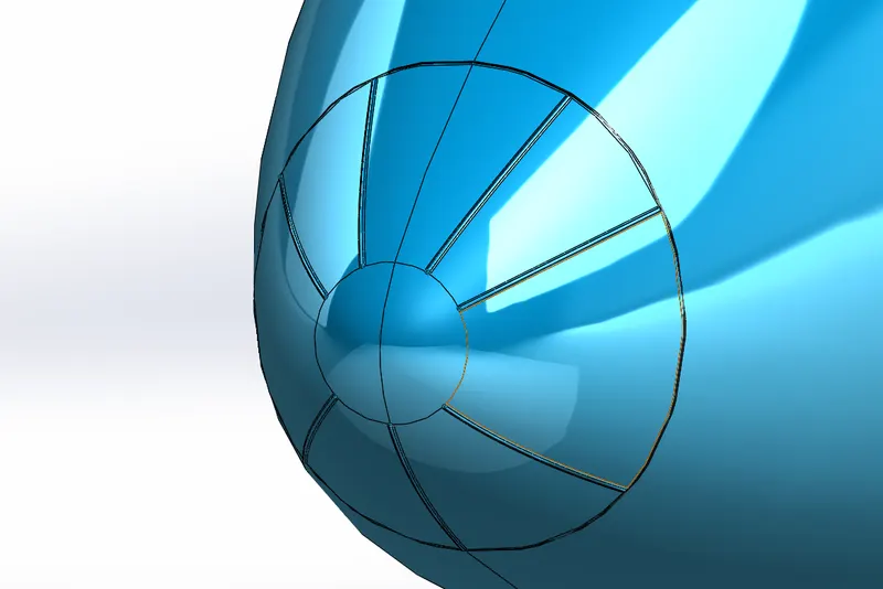
It reduces the drag of the aircraft and houses the radar and other instruments
The features used are:
- Sketch
- Split Line
- Fillet
- Mirror
- Sweep
-
Pitot Tubes
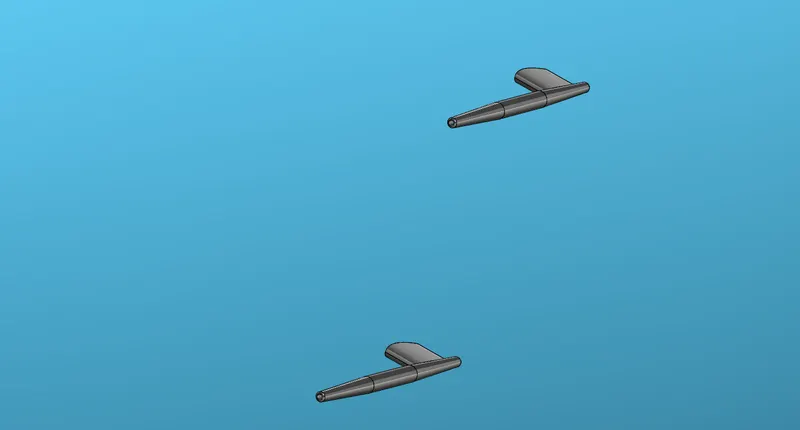
It measures the fluid flow velocity and determines the airspeed of an aircraft
The features used are:
- Sketch
- Sweep
- Cut Extrude
- Boss Extrude
- Chamfer
- Fillet
- Mirror
- Axis
- Plane
-
Cockpit Windows
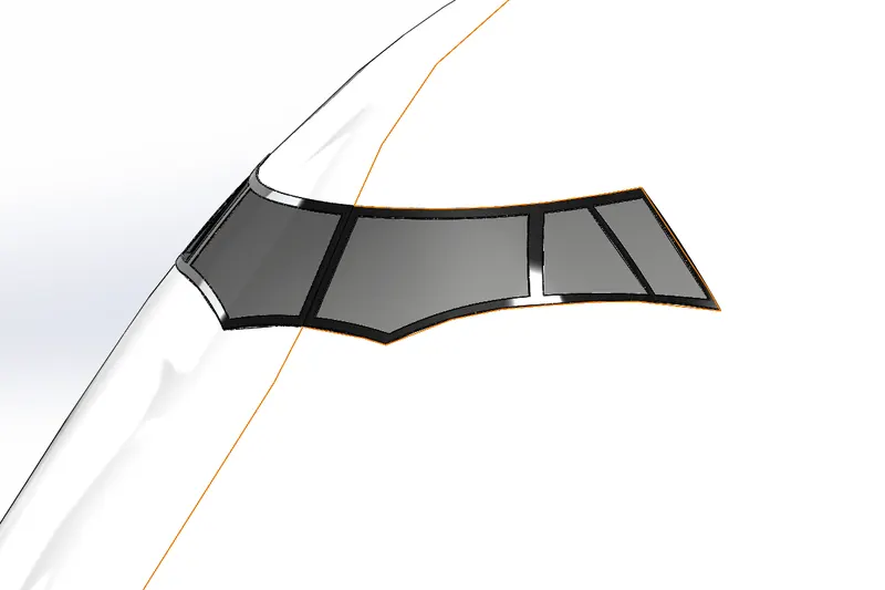
It is situated in the front of the fuselage. Helps the pilots to see what is infront of them.
The features used are:
- Sketch
- Split Line
- Surface offset
- Thicken
- Mirror
-
Windshield Wipers
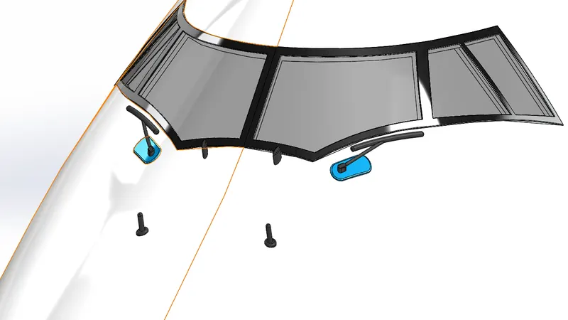
It works independently giving the pilot and co-pilot control over his/her windshield.
The features are used are:
- Sketch
- Sweep
- Boss Extrude
- Chamfer
- Mirror
- Combine
- Curve
- Move/Copy
-
Passenger Windows
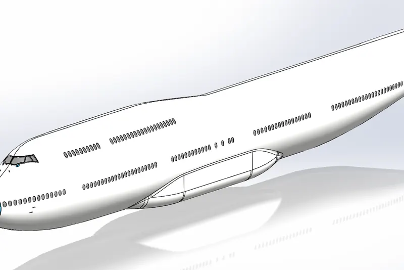
Helps the passengers to see outside from the aircraft.
The features used are:
- Sketch
- Split Line
-
Door & Hatches
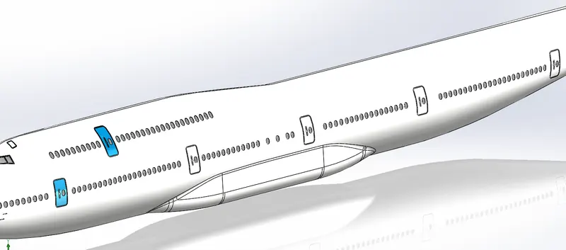
The door is designed to seal itself by taking advantage of pressure difference on its two sides and is used on the aircraft with cabin pressurization.
The features used are:
- Sketch
- Split Line
- Linear Pattern
- Offset Surface
- Thicken
- Fillet
-
Lights & Antennas
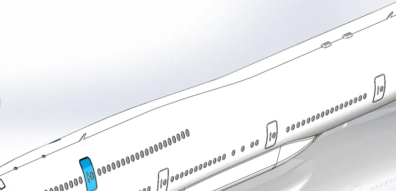
Lights are required on every aircraft to improve visibility to others. Antennas are used for proper communication.
The features used are:
- Sketch
- Revolve
- Split
- Linear Pattern
- Boss Extrude
- Draft
- Move/Copy
- Split Line
- Offset Surface
- Thicken
- Fillet
-
Auxiliary Power Unit
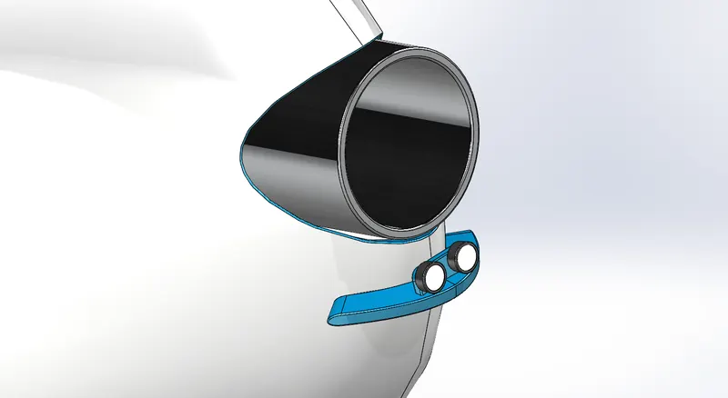
Provide energy for functions other than propulsion.
The features used are:
- Cut Extrude
- Boss Extrude
- Split Line
- Offset Surface
- Mirror
- Thicken
- Dome
- Fillet
-
Vertical Stabilizer
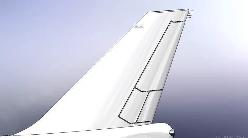
It keeps the nose of the aircraft from swinging side to side.
The features used are:
- Sketch
- Plane
- Offset Surface
- Surface Cut
- Boss Extrude
- Cut Extrude
- Fillet
- Loft
-
Horizontal Stabilizer
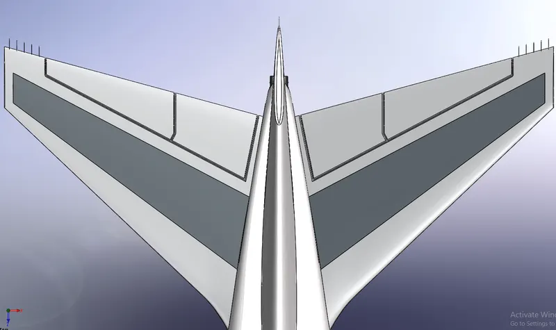
It keeps the nose from up-down motion.
The features used are:
- Curve
- Plane
- Loft
- Fillet
- Cut Extrude
- Split Line
- Offset Surface
- Thicken
- Boss Extrude
- Mirror
-
Wings
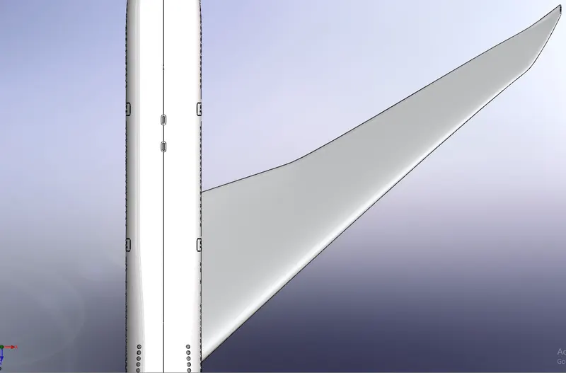
The features used are:
- Sketch
- Curve
- Plane
- Loft
- Fillet
- Offset Surface
- Surface Cut
- Delete Body
-
Flaps & Ailerons
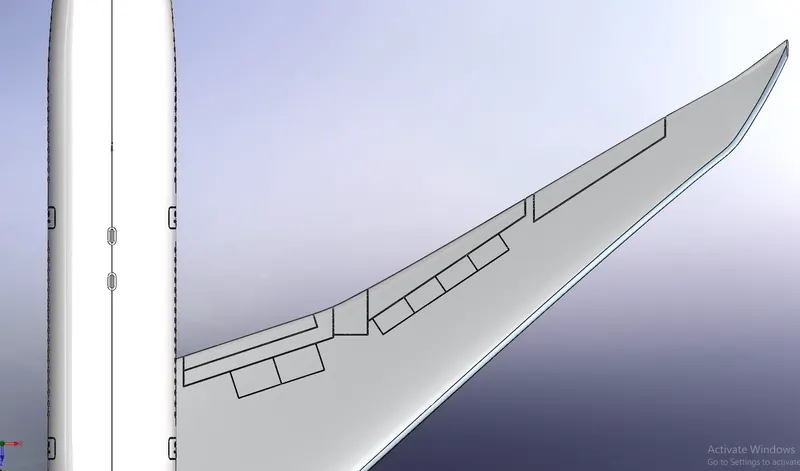
Flaps reduces the stalling speed and ailerons aids in controlling lateral balance.
The features used are:
- Cut Extrude
- Plane
- Split Line
- Offset Surface
- Thicken
- Fillet
-
Flap Track Fairings
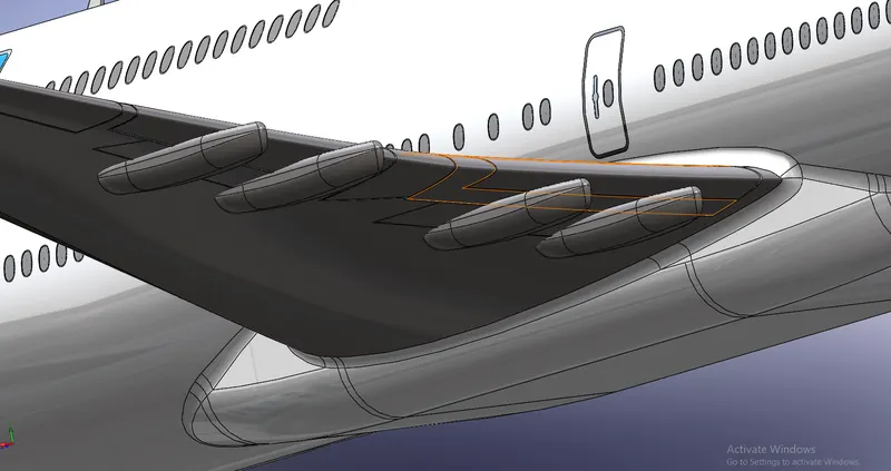
It is an enclosed mechanism for deploying the wing flaps and reduces wave drag.
The features used are:
- Sketch
- Boss Extrude
- Fillet
- Split
- Move/Copy
- Mirror
- Combine
-
Landing Gear Axis
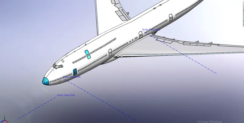
The features used are:
- Sketch
- Axis
-
Landing Gear Hatches Closed
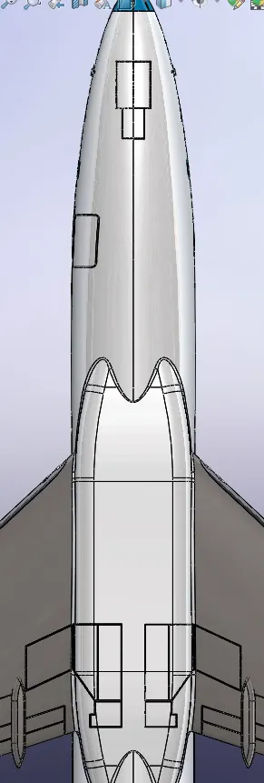
The features used are:
- Sketch
- Split Line
- Surface Offset
- Thicken’
- Fillet
- Mirror
-
Landing Gear Hatches Open
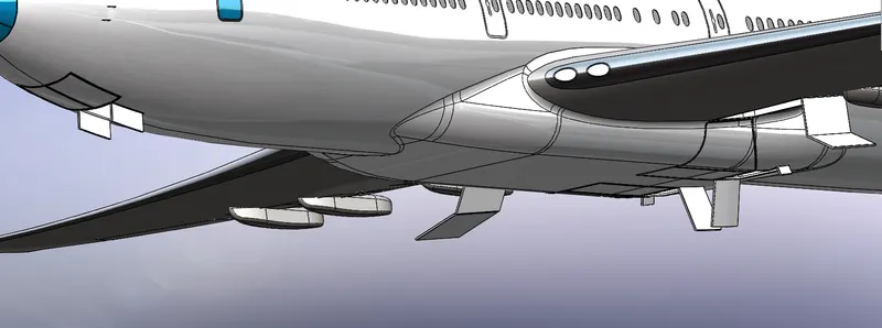
The features used are:
- Cut Extrude
- Plane
- Sweep Surface
- Thicken
- Fillet
- Mirror
- Boss Extrude
-
Livery
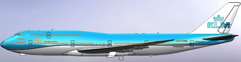
Applied appearance and sketch block in this section.
The feature used is:
- Split Line
-
Nose Gear Base
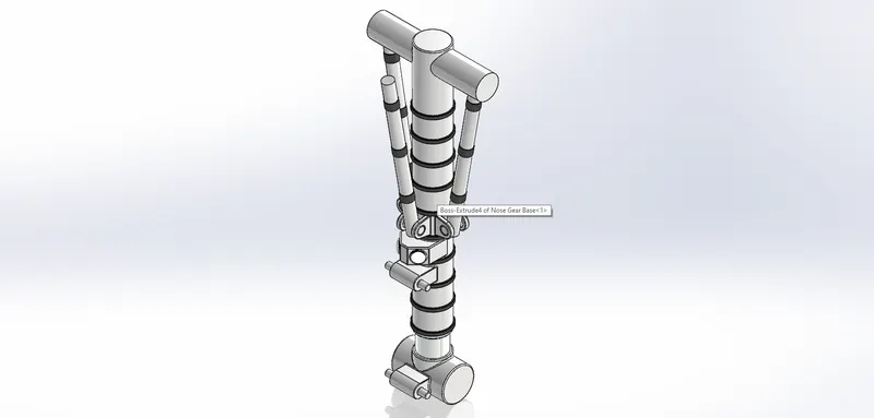
The features used are:
- Boss Extrude
- Fillet
- Split Line
- Sweep
- Dome
- Linear Pattern
- Circular Pattern
- Mirror
- Move Face
-
Nose Gear Suspension Arm
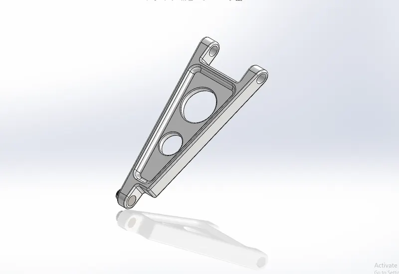
The Features used are:
- Boss Extrude
- Cut Extrude
- Fillet
- Mirror
-
Wheel
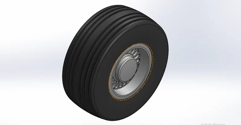
They are too rigid to be forced onto a rim like automotive tyres. The inboard and outboard hubs are bolted together with the tyre in the centre.
The features used are:
- Boss Extrude
- Cut Extrude
- Revolve
- Cut Revolve
- Fillet
- Dome
- Circular Pattern
- Chamfer
- Mirror
-
Nose Gear Assembly
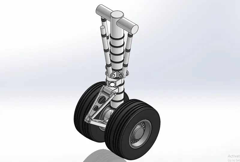
We have created a subassembly like shown to add in the main assembly. The parts included are Nose Gear Base, Nose Gear Suspension Arm and wheel.
-
Main Gear Base
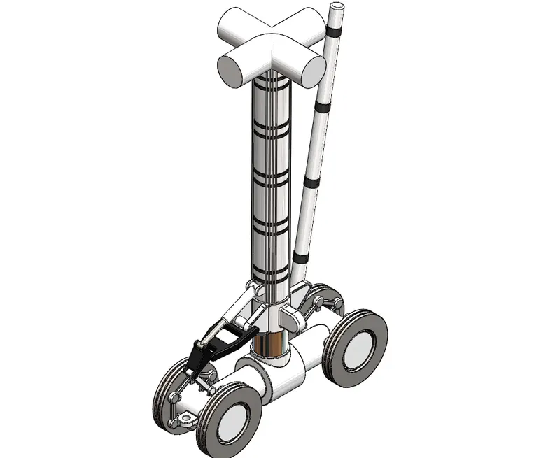
The Features used are:
- Boss Extrude
- Cut Extrude
- Fillet
- Circular pattern
- Linear pattern
- Sweep
- Combine
- Axis
-
Main Gear Suspension Arm
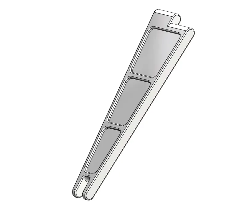
The Features used are:
- Boss Extrude
- Cut Extrude
- Fillet
- Mirror
- Axis
-
Main Gear Assembly
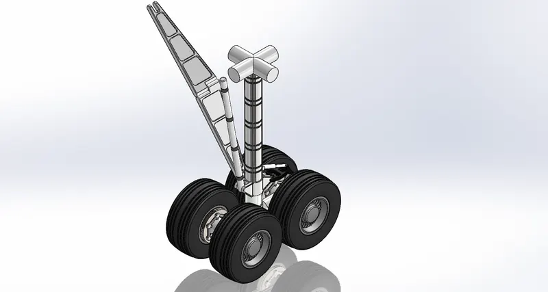
Another subassembly is made to attach in the main assembly. The assembly includes the main gear base, two suspension arms, and four wheels. Different mates were used to connect the parts.
-
Engine
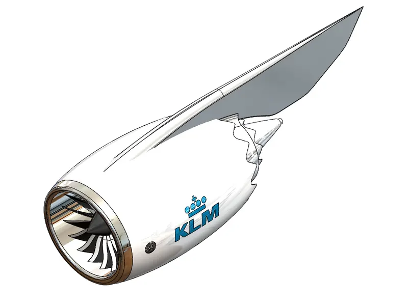
It is an advanced dual rotor, axial flow, high-bypass turbofan jet engine featuring a small fan, de-staged booster and de-staged low-pressure turbine.
The features used are:
- Revolve
- Split
- Circular Pattern
- Revolve-Thin
ASSEMBLY OF BOEING 747-8
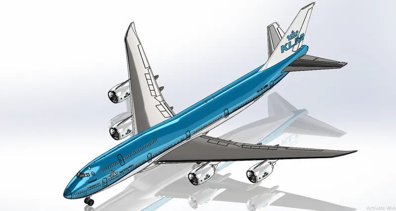
The sub-assemblies of nose gear and main gear are inserted and using the mates function they are assembled. The sub-assemblies are made to float to add flexibility and finally their flexibilities are synced so the nose gear and the main gear move in unison.
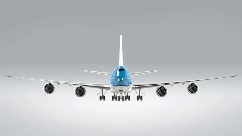
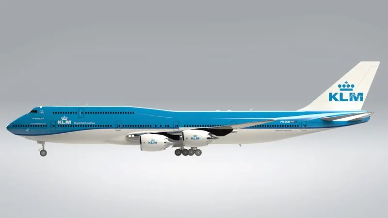
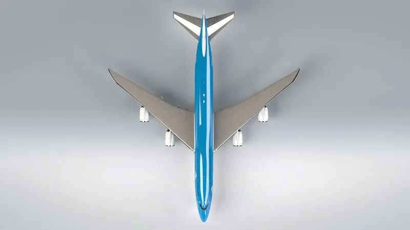
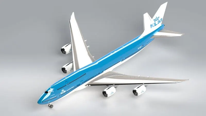
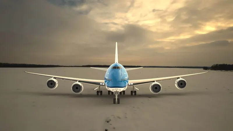
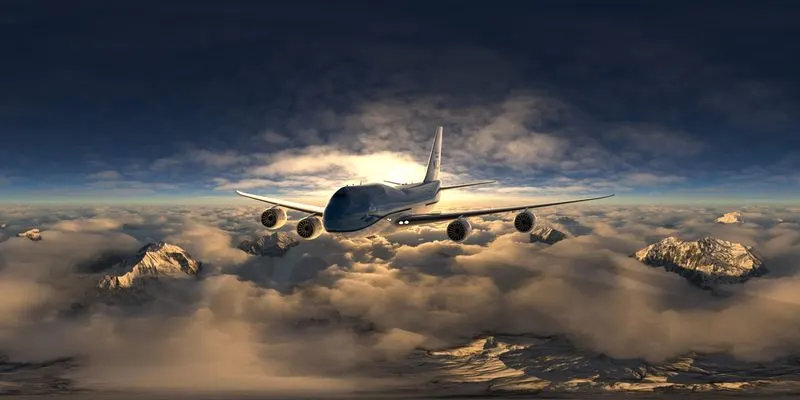
RENDERED IMAGES OF Boeing 747-8
Conclusion
The project on Boeing 747-8 helped us understand the different portions of solidworks such as Solid modelling, Surface modelling, Assembly Modelling, Rendering etc. It helped us to have knowledge on different commands. It helped us to get the idea that only with a proper blueprint, we can create the model using our own dimensions.