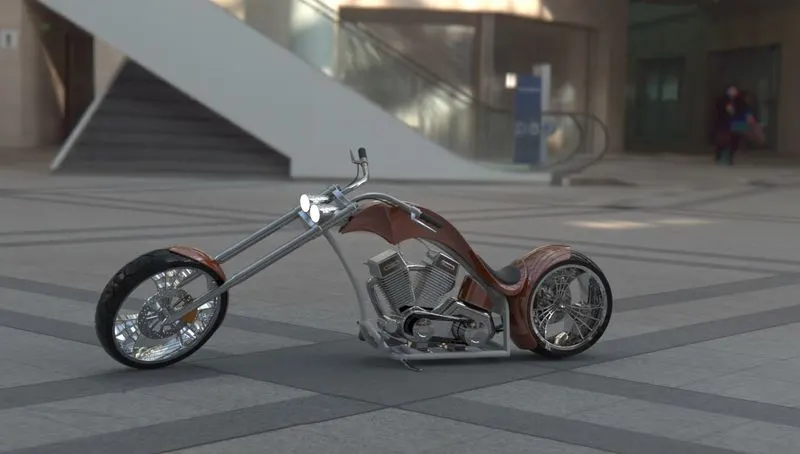
Photo Realistic Rendering
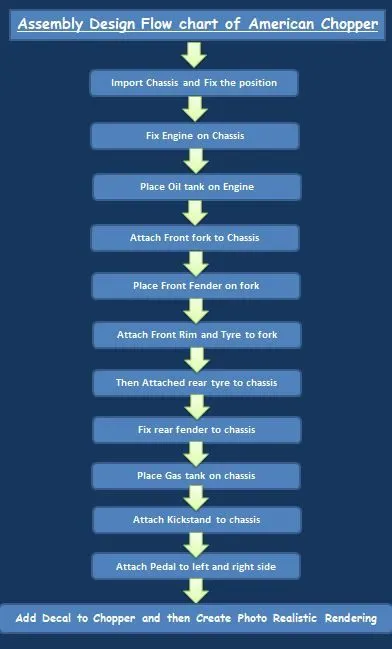
Assembly of American chopper:
Objective:
- To design individual parts of an American chopper with fully defined sketches and appropriate appearances.
- To assemble all the individual parts of the American chopper to create the chopper model.
- To render the chopper model by adding appearances, decals, lights, cameras, and background scene.
- To create photorealistic rendered images of the chopper using Solidworks Visualize.
Software used:
- Solidworks 2018
Introduction:
American Chopper:A chopper is a type of custom motorcycle. The chopper is perhaps the most extreme of all custom styles, often using radically modified steering angles and lengthened forks for a stretched-out appearance. Some of the characteristic features of choppers are long front ends with extended forks often coupled with an increased rake angle, hardtail frames (frames without rear suspension), very tall "ape hanger" or very short "drag" handlebars, lengthened or stretched frames, and larger than stock front wheels.
- The first choppers were built in America and tended to be based on Harley-Davidson motorcycles.
- Rather than being primarily performance oriented modifications, choppers are more about achieving a certain look.
- So the purpose of this project is to create an aesthetic model of a chopper using Solidworks and Solidworks Visualize.
Design methodology:
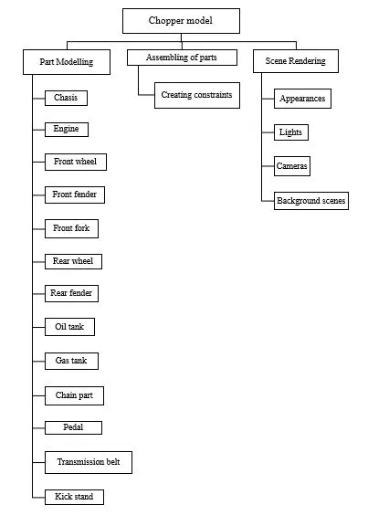
Details about feature and properties used in entire model to design different parts:
Offset:
- Offset is used to create a similar sketch at a required distance in the required direction parallel to the sketch.
Extrude
- Extrude is a type of feature available in solidworks to convert a 2D sketch into a 3D model.
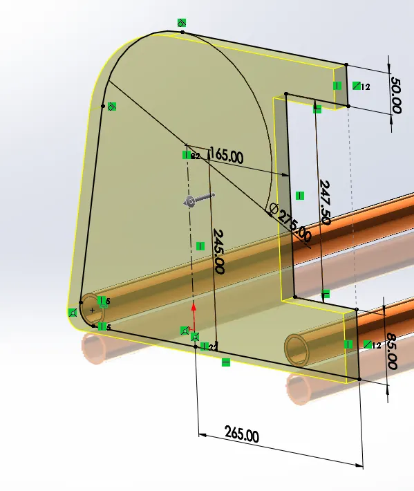
Fillet
- Fillet/Round creates a rounded internal or external face on the part. You can fillet all edges of a face, selected sets of faces, selected edges, or edge loops.
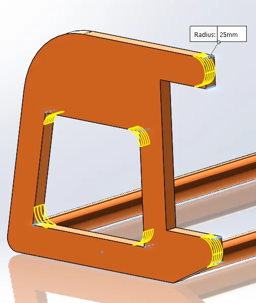
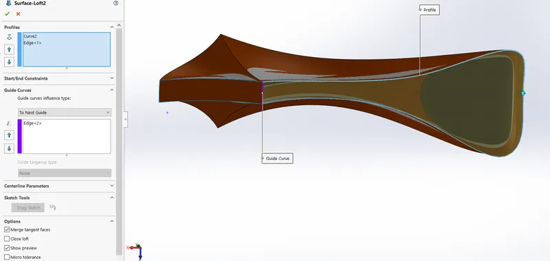
Loft
- The loft feature in SOLIDWORKS allows you to generate complex geometry in a single feature. It does this by interpolating surfaces between various cross-sections of a model. These cross-sections can be sketches, faces, or edges. In the loft interface, these cross-sections are considered “Loft Profiles”.
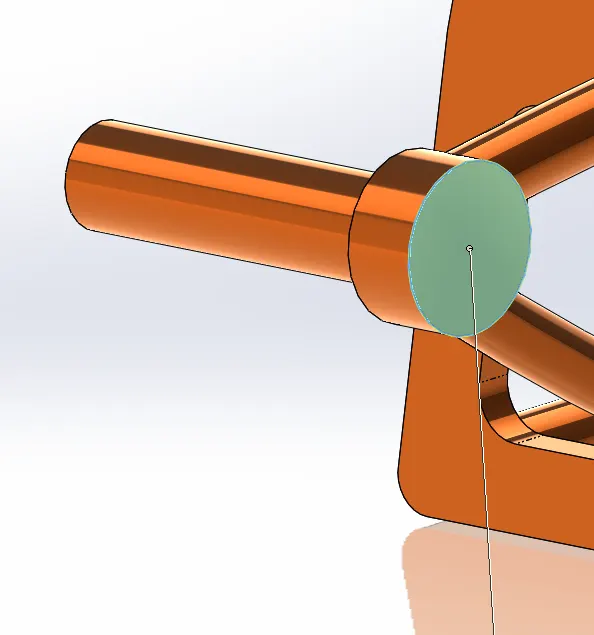
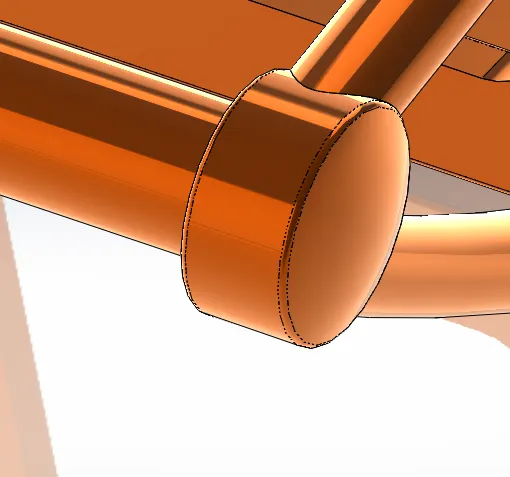
Dome
- Faces to Dome. Select one or more planar or non-planar faces. You can apply domes to faces whose centroid lies outside the face. This allows you to apply domes to irregularly shaped contours.
Split
- The SOLIDWORKS Split Line tool is used to project an entity (sketch, solid, surface, face, plane, or surface spline) onto other surfaces or curved/planar faces. You are also able to split faces on multiple bodies with one command.
Extrude Cut:
- The extrude cut is used to remove unwanted material from the solid model as per the sketch defined. Based on the sketch the material is removed from the component.
Trim:
- Trim is used to remove unwanted sketch entities or extra portions of the sketch. It works based on some reference points, edges.
Revolve:
- Revolve is used to create a revolved 3D model using a sketch profile using an axis of rotation. The profile was created with the revolution up to 3600 axis rotation.
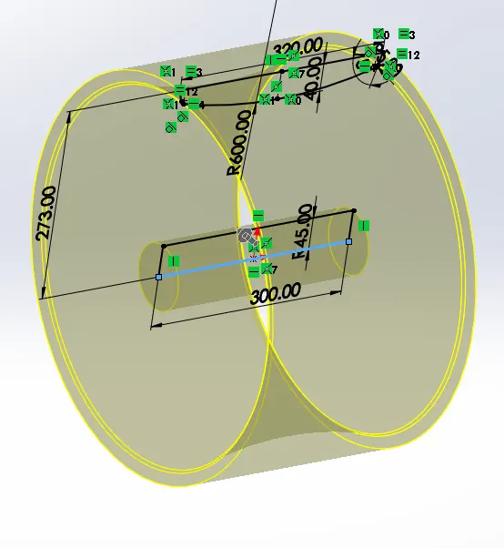
Move/copy Body
- Move/ Copy body is used to move/copy the body from one place to other places in the fork.
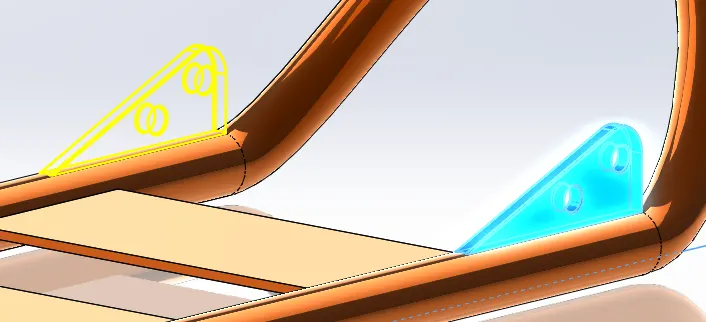
Mirror
- By using mirror faces with a mid-plane selected only the chosen faces within the revolve will be mirrored. Mirroring bodies can be used whether in a single or multi body part and allows you to select solid geometry instead of the features and faces in a body. In the fork part the one part of the fork is created and the other part is mirrored. Then the parts are manually combined.
Project Curve
- Project curve is the kind of 3D curve which is projected on the basis of the two different 2D sketches.
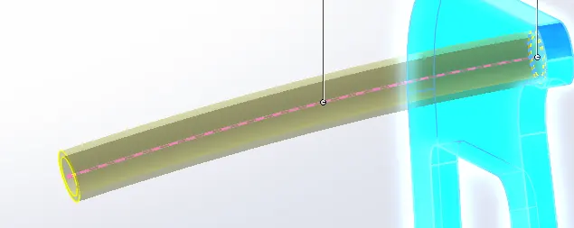
Sweep
- With the Sweep feature we can create a shape by moving a 2D sketch Profile along a 2D or 3D sketch Path.
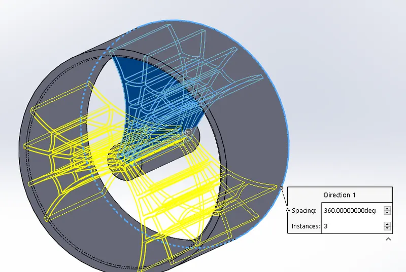
Circular Pattern:
- A circular pattern is used to create a solid feature in a circular direction with respect to the reference axis of rotation up to user-defined instances.
Revolve Cut:
- Revolve cut is used to remove solid geometry by revolving the sketch profile along a reference axis from the selected solid body.
Parts to design for American chopper:
- Transmission Belt
- Kickstand
- Front Fender
- Rear fender
- Oil Tank
- Chain
- Pedal
- Front Wheel
- Rear-wheel
- Front Fork
- Chassis
- Engine
- Gas Tank.
Design:
1.Transmission belt:
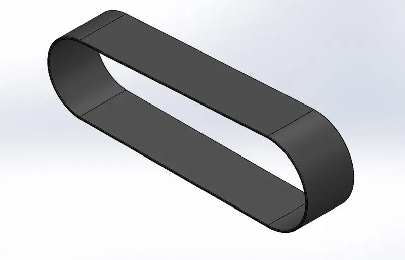
A belt is a loop of flexible material used to link two or more rotating shafts mechanically.Transmission Belt is a loop of flexible material used to transmit power by the means of pulleys. Belts transmit power efficiently through the pulleys. It is an power transmission. Other advantages are noiseless working, shock absorption during working, no lubrication, minimal maintenance, high tolerance for misalignment.
Commands used:
- Sketch
- Offset
- Extrude
- Fillet
- Appearances
Transmission belt image:
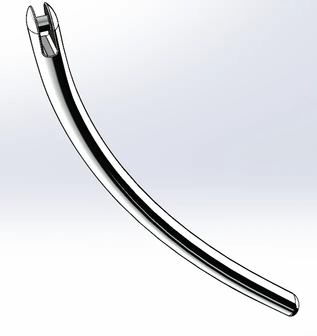
2.Kickstand:
The kickstand is a metal rod attached to a bicycle or motorcycle, lying horizontally when not in use. The kickstand flips down to touch the ground and provide support.
Commands used:
- 2d sketch
- Ellipse
- Spline
- Pierce
- Loft
- Cut extrude
- Boss extrudes
- Split.
Kickstand image:
3.Front fender:
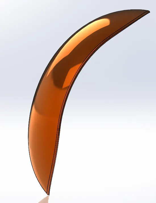
A fender is the part of a vehicle that protects and frames its wheels and keeps from Dust particals such as stones, mud, liquids on the roads,The front fender is placed in front face of the vehicle and another way we called fender as mudguard.
Commands used:
- 2d sketch
- 3-point arc
- offset
- Extend
- Trim
- Revolve
- spline
- Fillet.
Front fender image:
4. Rear Fender:
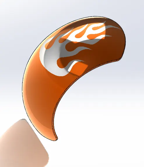
Fender(mudguard) is the same as front fender and also prevents sand, mud, rocks, liquids, and other road spray from being thrown into the air by the rotating tyre.
Commands used:
- 2d sketch
- 3-point arc
- Extend
- Trim
- Revolve
- spline
- Fillet
- Shell.
Rear Fender image:
5.Oil Tank:
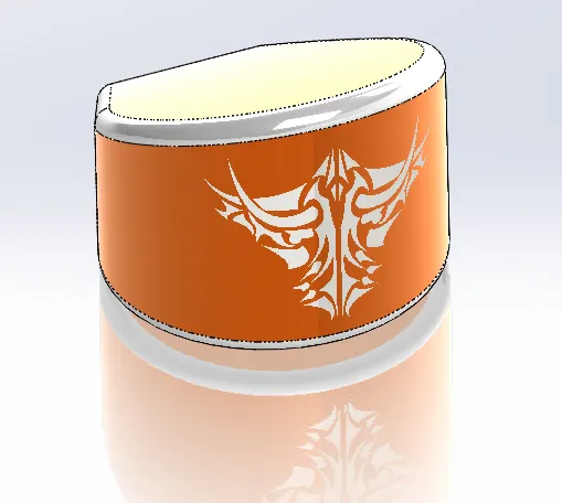
It is a container for storing oil. Stores the oil for lubrication and cooling purposes.
Commands used:
- Lines
- 3-point arc
- Boss Extrude
- Combine
- Fillet
- Shell
Oil Tank image:
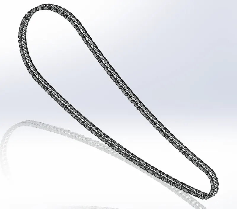
6.Chain:
Chain Drive is a mechanism to transfer power from one place to another; these are used to perform three basic functions: transmitting power, conveying materials, and timing purposes. Chain and sprocket drives are used to transmit power from one component to another. Specifically, they transfer speed and torque through the use of a linked chain and sprockets. In automobiles, roller chains are used in these drives to transmit power and torque.
Commands used:
- 2d sketch
- circles
- 3point arc
- Slot
- Block
- Fillet
- Curve Pattern
- Mirror
Chain image:
7.Pedal:
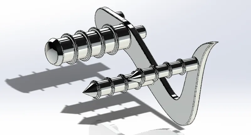
Foot pegs can be developed or manufactured from a variety of materials; some are made from aluminium, steel, and also titanium. The pedal is used to rest feet while driving a two-wheeler. It is an extended piece from the chassis which is used for resting feet to maintain balance and comfort while riding the vehicle.
Commands used:
- 2d sketch
- Lines
- Circles
- Fillets
- Revolve
- Dome
- Chamfer
- Linear Pattern
Pedal image:
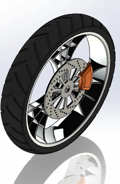
8.Front Wheel:
It is a circular object that revolves on an axle and is fixed below a vehicle or other object to enable it to move easily over the ground.front wheel has been attached with four parts they are
- Rim
- Disc brake (Rotor)
- Tyre
- Caliper
Rim: The rim is the "outer edge of a wheel, holding the tire". It makes up the outer circular design of the wheel on which the inside edge of the tire is mounted on vehicles such as automobiles.
Brake Caliper: A disc brake is a type of brake that uses the calipers to squeeze pairs of pads against a disc or "rotor" to create friction. This action slows the rotation of a shaft, such as a vehicle axle, either to reduce its rotational speed or to hold it stationary. The energy of motion is converted into waste heat which must be dispersed.
Commands used:
- 2d sketch
- Straight lines
- 3-point arc
- sketch fillet
- revolve
- spline
- extend
- trim
- cut extrude
- offset
- cut revolve
- circular pattern
- chamfer
- fillet
- corner centre point rectangle.
Front wheel image:
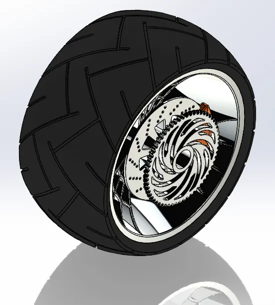
9.Rear Wheel:
A wheel is a circular block of a hard and durable material at whose center has been bored a circular hole through which is placed a front axle bearing about which the wheel rotates when the moment is applied by gravity or torque to the wheel.Rear wheel has been attached with five parts they are
- Rim
- Disc brake (Rotor)
- Tyre
- Sprocket
- Caliper
Commands used:
- 2d sketch
- Straight lines
- 3-point arc
- sketch fillet
- revolve
- spline
- extend
- trim
- cut extrude:
- offset
- cut revolve
- circular pattern
- chamfer
- fillet
- corner centre point rectangle.
Rear wheel image:
10.Front Fork:
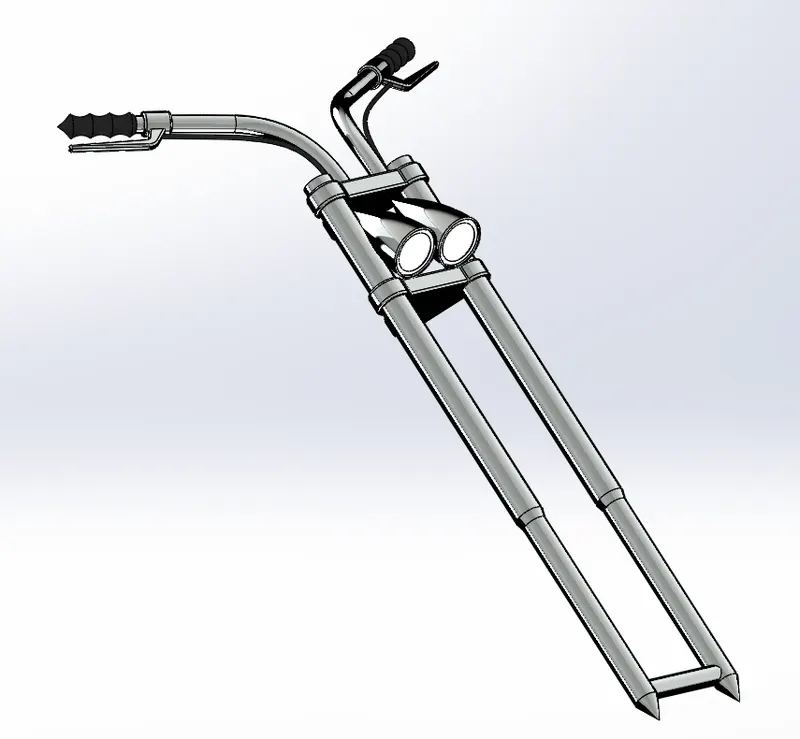
The element which connects the front wheel and axle to the rest of the frame is known as a front fork. The triple clamp or yoke is one of the main parts of the front fork. The front fork contains a front brake and front suspension.
The fork and its attachment points on the frame establish the critical geometric parameters of rake and trail, which play a major role in defining how a motorcycle handles and dives during braking. While the standard telescopic fork arrangement is found with few major differences among mainstream street motorcycles since the 1970s, historically there have been many variations, including trailing or leading link, springer, Earles, girder, and others, as well as non-fork steering such as hub-centre steering.
Commands used:
- 2d sketch
- Straight Lines
- Revolve
- circle
- Fillets
- Linear Pattern
- spline
- Cut Extrude
- Dome
- Move Body
- Curve
- sweep
- plane
- mirror
- combine
Front fork image:
11.Chassis
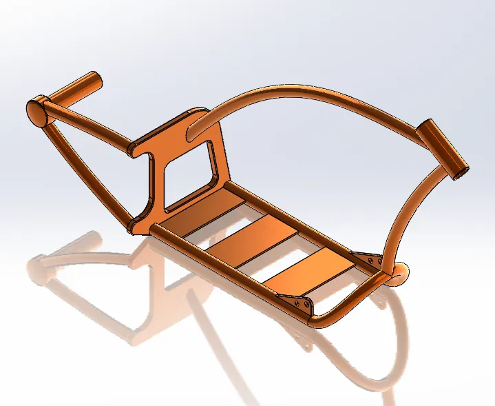
A chassis is the backbone of a vehicle,chassis is a vehicle frame, the underpart of a motor vehicle, on which the body is mounted; if the running gear such as wheels and transmission, and sometimes even the driver's seat, are included, then the assembly is described as a rolling chassis.
Commands used:
- sketch pictures
- splines
- curves
- mirror
- boss extrude
- cut extrude
- chamfer
- dome
- split
- revolve
- combine
Chassis image:
12.Engine:
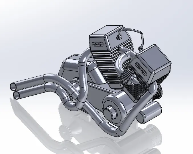
Motorcycle engines work the same way that car engines do. They consist of pistons, a cylinder block, and a head, which contains the valve train. The pistons move up and down in the cylinder block, driven by explosions of a fuel-air mixture that has been ignited by a spark. Valves open and close to allow the fuel-air mixture to enter the combustion chamber. As the pistons move up and down, they turn a crankshaft, which transforms the energy from the pistons into rotary motion. The rotational force of the crankshaft is transmitted, via the transmission, to the rear wheel of the motorcycle.Motorcycle engines are generally classified by one of three characteristics: the number of cylinders they possess, the capacity of their combustion chambers or the number of strokes in their power cycles.
Commands used:
- 2d sketch
- sketch pictures
- straight lines
- circles
- boss extrude
- fillet
- revolve
- plane
- dome
- circular pattern
- chamfer
- linear pattern
- mirror
- cut extrude
- combine
- mirror
- curve
- composite curve
- spilt.
Engine image:
13.Gas Tank:
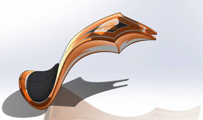
Storage of fuel: the system must contain a given quantity of fuel and must avoid leakage and limit evaporative emissions.the fuel tank must be filled in a secure way, without sparks.Provide a method for determining the level of fuel in the tank, gauging (the remaining quantity of fuel in the tank must be measured or evaluated).Venting (if overpressure is not allowed, the fuel vapors must be managed through valves).Feeding of the engine (through a pump).Anticipate potentials for damage and provide safe survival potential.
Commands used:
- 2d sketch
- spline
- surface sweep
- surface trim
- surface boundary
- surface loft
- curve
- mirror
- surface knit
- surface extrude
- fillet
- cut extrude
- shell.
Gas Tank image:
Assembly:
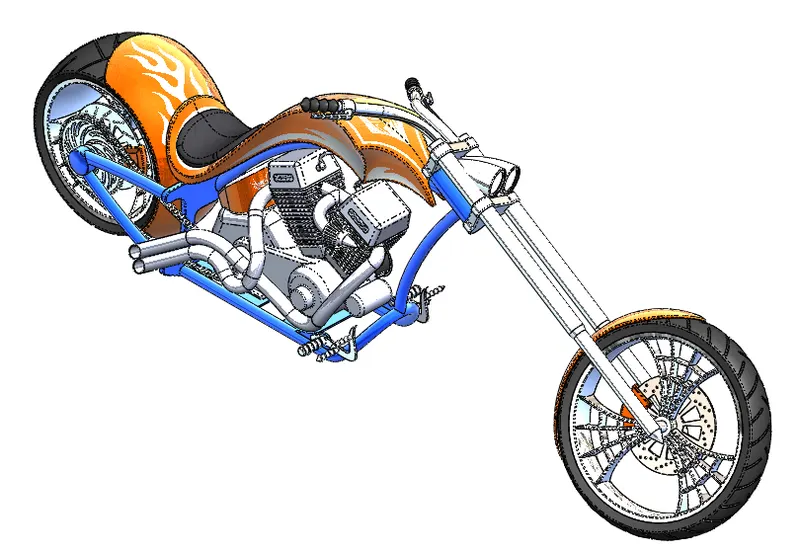
Assembly image:
Isometric view:
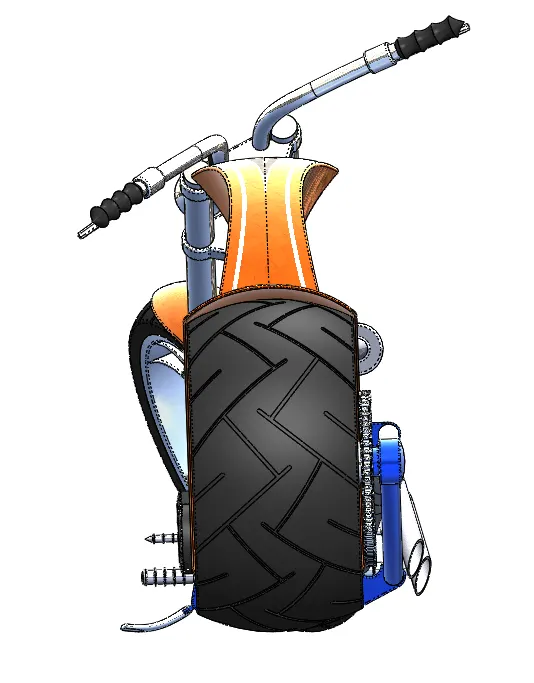
Back view:
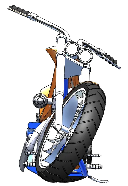
Front view:
Left view:
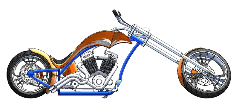
Right view:
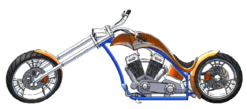
Over-all view:
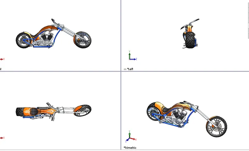
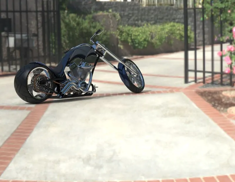
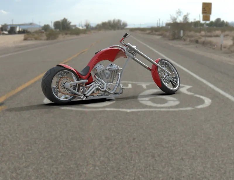
Rendering Images of Assembly:
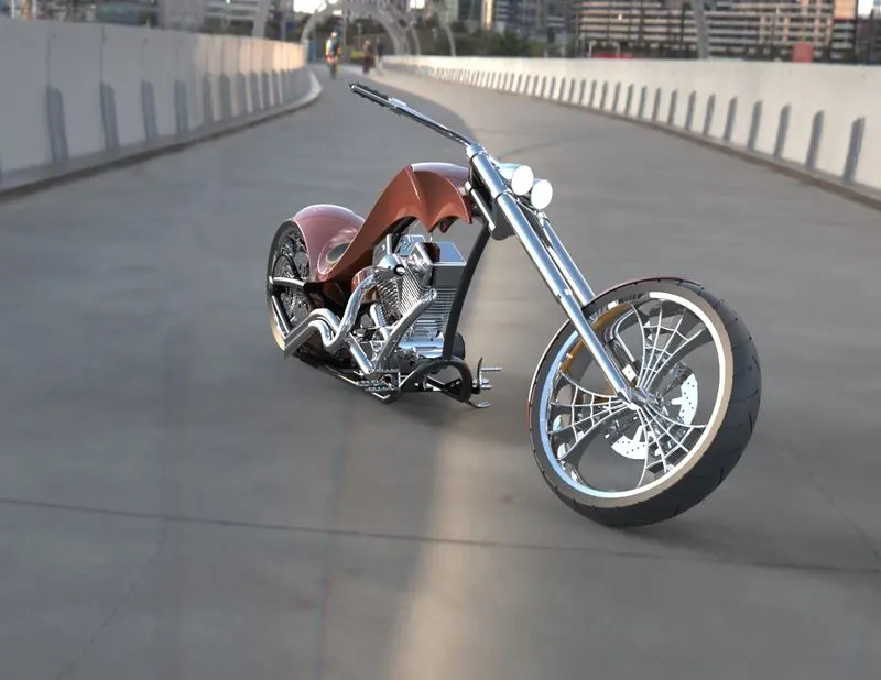
Rendering is the automatic process of generating a photorealistic or non-photorealistic image from a 2D or 3D (or models in what collectively could be called a scene file) by means of the computer programs. Also, the results of displaying such a model can be called a render. A scene file contains objects in a strictly defined language or data structure; it would contain geometry, viewpoint, textures, lighting, and shading information as a description of the virtual scene. The data contained in the scene file is then passed to a rendering program to be processed and output to a digital image or raster graphics image file. The term "rendering" maybe by analogy with an "artist's rendering" of a scene.
Docklands Bridge:
Sunny Driveway:
SRoute 66:
Tokyo Atrium: