Photo Realistic Rendering
Assembly of American Chopper
Objective:
- To design Individual components of chopper Assembly with fully defined sketches.
- To assemble all components with Suitable constraints.
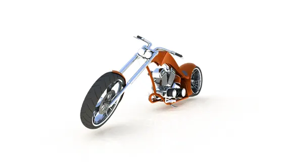
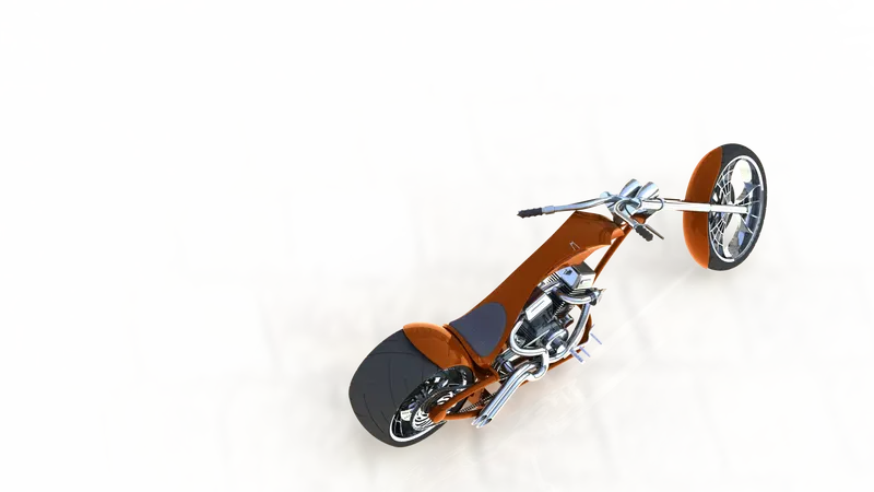
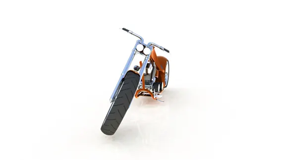
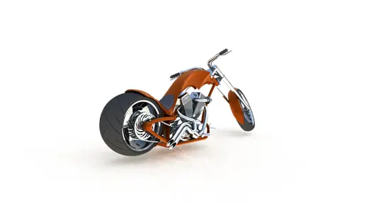
- To Render Chopper Assembly with Proper Appearance, Decals & scenes
Introduction
Chopper is a customized Bike with Highly precise machined Parts consisting of Powerful Engine, Chassis, Front Wheel, Rear Wheel, Front Fender, Rear Fender, Oil Tank, Gas tank, chain, Pedal, Kickstand & Transmission belt.
Design Methodology
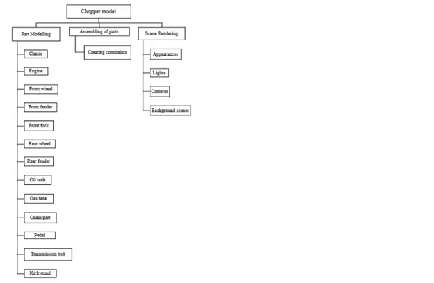
Description:
Orthographic views for Indivudual components and Assembly is shown below.
1.CHASSIS
- FRONT VIEW
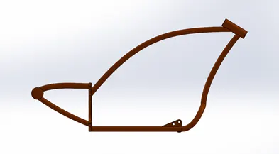
- SIDE VIEW
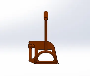
- ISOMETRIC VIEW
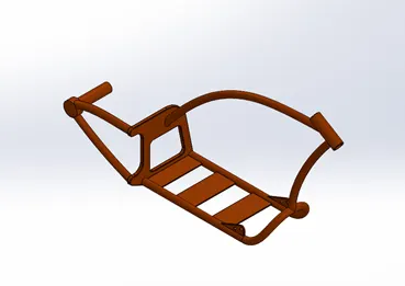
Tools & Features Used
- Sketch: To create required Sketch
- Line: To create continuous & construction Line
- Circle: To draw circle
- Spline: To draw Curves through Interpolation of Points
- Intersection Curve: Obtained from intersection of two curves
- Sweep: To obtain a solid body along Profile path
- Extrude: To obtain 3d Solid from 2D sketch
- Cut-extrude: To subtract a solid portion from Solid using 2D sketch
- Reference Plane: To create a reference Plane from an Existing Plane or points
- Mirror: To mirror features and sketches along Selected reference
- Split: To split Solid bodies
- Combine: To merge Two Solid bodies
- Dome: To create dome Surface
- Composite curve: To create a Curve from reference of two or more curves
- Fillet: To convert sharp internal or external edges into smooth/round edges
- Chamfer: To convert sharp edges into Bevel edges
- Smart Dimensions: To add /edit /delete dimension in 2D sketch
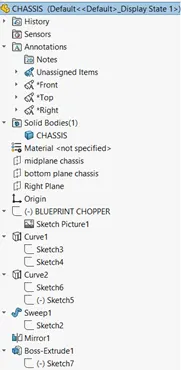
MODEL TREE
2.ENGINE
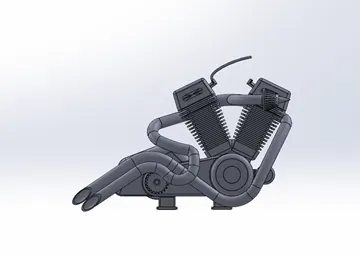
- FRONT VIEW
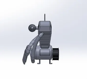
- SIDE VIEW
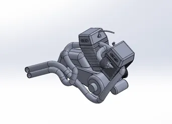
- ISOMETRIC VIEW
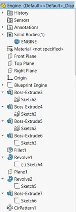
Tools & Features Used
- Sketch Picture: To insert Picture for Reference
- Sketch: To create required Sketch
- Line: To create continuous & construction Line
- Circle: To draw circle
- Arc: To draw an arc
- Spline: To draw Curves through Interpolation of Points
- Convert entities: To convert Entities for reference into New sketch as lines
- Intersection Curve: Obtained from intersection of two curves
- Boss-Sweep: To obtain a solid body along Profile path
- Boss-Extrude: To obtain 3d Solid from 2D sketch
- Boss-Revolve: to revolve 2D sketch to obtain 3D solid
- Cut-extrude: To subtract a solid portion from Solid using 2D sketch
- Composite curve: To create a Curve from reference of two or more curves
- Reference Plane: To create a reference Plane from an Existing Plane or points
- Mirror: To mirror features and sketches along Selected reference
- Split: To split Solid bodies
- Combine: To merge Two Solid bodies
- Dome: To create dome Surface
- Fillet: To convert sharp internal or external edges into smooth/round edges
- Circular Pattern: To create pattern along circular reference
- Linear Pattern: To create pattern along linear reference
- Chamfer: To convert sharp edges into Bevel edges
- Smart Dimensions: To add /edit /delete dimension in 2D sketch
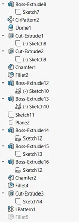
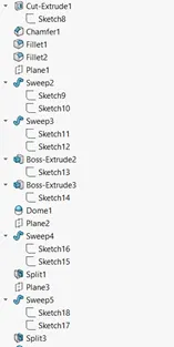
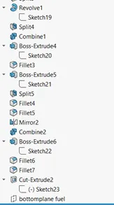
MODEL TREE
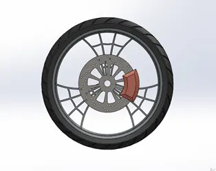
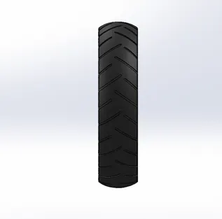
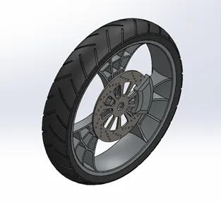
3.FRONT WHEEL
- FRONT VIEW
- SIDE VIEW
- ISOMETRIC VIEW
Tools & Features Used
- Sketch: To create required Sketch
- Line: To create continuous & construction Line
- Circle: To draw circle
- Arc: To draw an arc
- Spline: To draw Curves through Interpolation of Points
- Convert entities: To convert Entities for reference into New sketch as lines
- Boss-Extrude: To obtain 3d Solid from 2D sketch
- Boss-Revolve: to revolve 2D sketch to obtain 3D solid
- Cut-extrude: To subtract a solid portion from Solid using 2D sketch
- Cut-Revolve: : To subtract a solid portion from Solid using 2D sketch
- Combine: To merge Two Solid bodies
- Dome: To create dome Surface
- Fillet: To convert sharp internal or external edges into smooth/round edges
- Circular Pattern: To create pattern along circular reference
- Linear Pattern: To create pattern along linear reference
- Chamfer: To convert sharp edges into Bevel edges
- Smart Dimensions: To add /edit /delete dimension in 2D sketch
4.FRONT FENDER
- FRONT VIEW
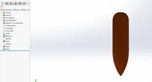
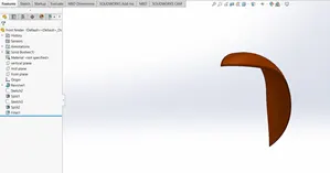
- SIDE VIEW
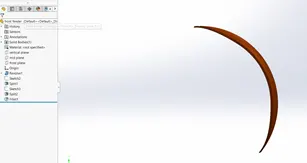
- ISOMETRIC VIEW
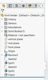
MODEL TREE
Tools & Features Used
- Sketch: To create required Sketch
- Line: To create continuous & construction Line
- Spline: To draw Curves through Interpolation of Points
- Split: To separate or Split bodies
- Boss-Revolve: to revolve 2D sketch to obtain 3D solid
- Fillet: To convert sharp internal or external edges into smooth/round edges
- Chamfer: To convert sharp edges into Bevel edges
- Smart Dimensions: To add /edit /delete dimension in 2D sketch
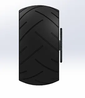
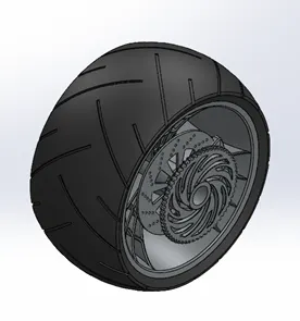
5.REARWHEEL
- FRONT VIEW
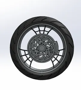
- SIDE VIEW
- ISOMETRIC VIEW
Tools & Features Used
- Sketch: To create required Sketch
- Line: To create continuous & construction Line
- Circle: To draw circle
- Spline: To draw Curves through Interpolation of Points
- Convert entities: To convert Entities for reference into New sketch as lines
- Boss-Extrude: To obtain 3d Solid from 2D sketch
- Boss-Revolve: to revolve 2D sketch to obtain 3D solid
- Cut-extrude: To subtract a solid portion from Solid using 2D sketch
- Cut-Revolve: : To subtract a solid portion from Solid using 2D sketch
- Combine: To merge Two Solid bodies
- Fillet: To convert sharp internal or external edges into smooth/round edges
- Circular Pattern: To create pattern along circular reference
- Linear Pattern: To create pattern along linear reference
- Chamfer: To convert sharp edges into Bevel edges
- Smart Dimensions: To add /edit /delete dimension in 2D sketch
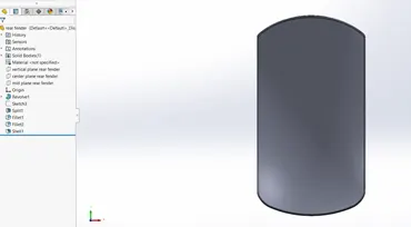
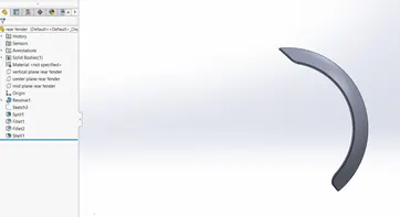
6. REAR FENDER
- FRONT VIEW
- SIDE VIEW
- ISOMETRIC VIEW
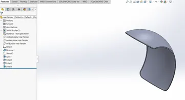
- MODEL TREE
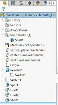
Tools & Features Used
- Sketch: To create required Sketch
- Line: To create continuous & construction Line
- Spline: To draw Curves through Interpolation of Points
- Split: To separate or Split bodies
- Boss-Revolve: to revolve 2D sketch to obtain 3D solid
- Fillet: To convert sharp internal or external edges into smooth/round edges
- Chamfer: To convert sharp edges into Bevel edges
- Smart Dimensions: To add /edit /delete dimension in 2D sketch
7. OIL TANK
- FRONT VIEW
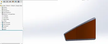
- SIDE VIEW
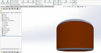
- ISOMETRIC VIEW
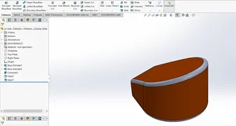
- MODEL TREE
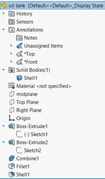
Tools & Features Used
- Sketch: To create required Sketch
- Line: To create continuous & construction Line
- Spline: To draw Curves through Interpolation of Points
- Split: To separate or Split bodies
- Boss-Extrude: to obtain 3D sketch From 2D sketch
- Combine: To combine or merge Solid bodies
- Shell: To convert Solid bodies into Shell
- Fillet: To convert sharp internal or external edges into smooth/round edges
- Smart Dimensions: To add /edit /delete dimension in 2D sketch
8.GAS TANK
- FRONT VIEW
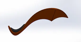
- SIDE VIEW
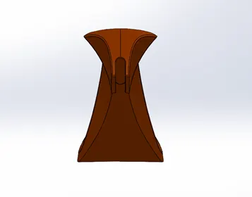
- ISOMETRIC VIEW
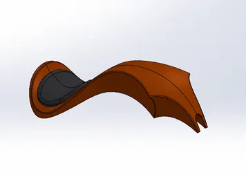
Tools & Features Used
- Sketch Picture: To insert Picture for Reference
- Sketch: To create required Sketch
- Line: To create continuous & construction Line
- Spline: To draw Curves through Interpolation of Points
- Boss-Extrude: To obtain 3d Solid from 2D sketch
- Reference Plane: To create a reference Plane from an Existing Plane or points
- Mirror: To mirror features and sketches along Selected reference
- Split: To split Solid bodies
- Combine: To merge Two Solid bodies
- Fillet: To convert sharp internal or external edges into smooth/round edges
- Surface loft: to create surface along profiles
- Surface knit: To combine adjacent non intersecting surface
- Boundary surface: To create surface from close Profile
- Cut Sweep: To cut the surface along profile through sweep along reference
- Shell: To convert Solid bodies into Shell
- Smart Dimensions: To add /edit /delete dimension in 2D sketch
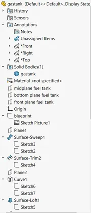
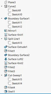
MODEL TREE
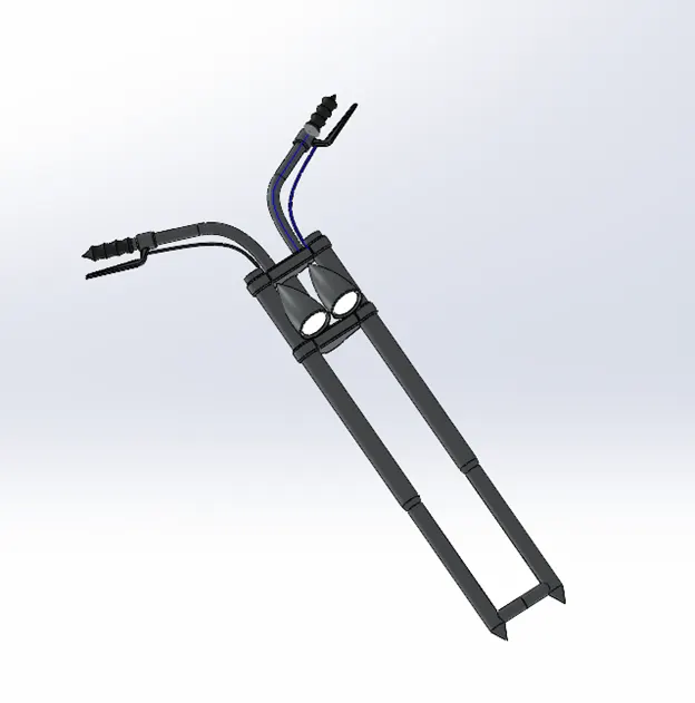
9.FRONT FORK
- ISOMETRIC VIEW
Tools & Features Used
- Sketch: To create required Sketch
- Line: To create continuous & construction Line
- Circle: To draw circle
- Arc: To draw an arc
- Spline: To draw Curves through Interpolation of Points
- Convert entities: To convert Entities for reference into New sketch as lines
- Boss-Extrude: To obtain 3d Solid from 2D sketch
- Boss-Revolve: to revolve 2D sketch to obtain 3D solid
- Cut-extrude: To subtract a solid portion from Solid using 2D sketch
- Combine: To merge Two Solid bodies
- Dome: To create dome Surface
- Fillet: To convert sharp internal or external edges into smooth/round edges
- Linear Pattern: To create pattern along linear reference
- Chamfer: To convert sharp edges into Bevel edges
- Smart Dimensions: To add /edit /delete dimension in 2D sketch
9.CHAIN
- FRONT VIEW
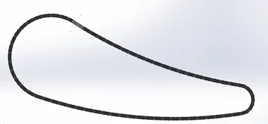
- SIDE VIEW
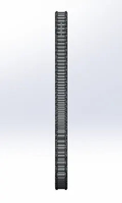
- ISOMETRIC VIEW
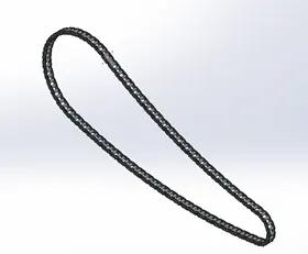
Tools & Features Used
- Sketch: To create required Sketch
- Line: To create continuous & construction Line
- Circle: To draw circle
- Arc: To draw an arc
- Spline: To draw Curves through Interpolation of Points
- Block: To create separate block & save as 2d feature
- Boss-Extrude: To obtain 3d Solid from 2D sketch
- Mirror: To mirror features and sketches along Selected reference
- Combine: To merge Two Solid bodies
- Fillet: To convert sharp internal or external edges into smooth/round edges
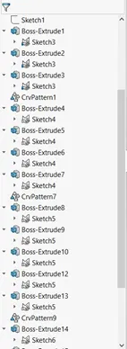
- Curve Pattern: To create pattern along curved reference
- Smart Dimensions: To add /edit /delete dimension in 2D sketch
MODEL TREE
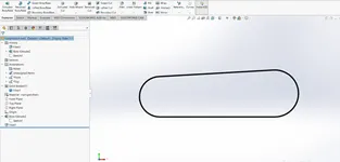
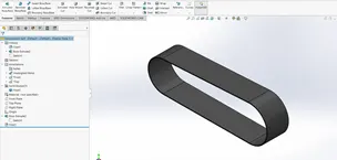
10.TRANSMISSION BELT
- FRONT VIEW
- ISOMETRIC VIEW
Tools & Features Used
- Sketch: To create required Sketch
- Line: To create continuous & construction Line
- Circle: To draw circle
- Arc: To draw an arc
- Boss-Extrude: To obtain 3d Solid from 2D sketch
- Fillet: To convert sharp internal or external edges into smooth/round edges
- Smart Dimensions: To add /edit /delete dimension in 2D sketch
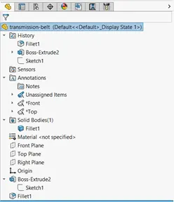
MODEL TREE
11.PEDAL
- FRONT VIEW
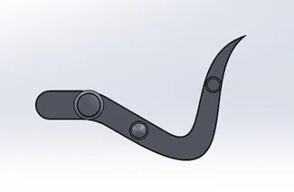
- SIDE VIEW
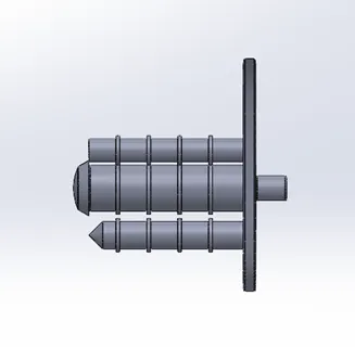
- ISOMETRIC VIEW
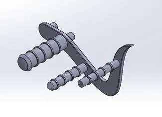
Tools & Features Used
- Sketch: To create required Sketch
- Line: To create continuous & construction Line
- Circle: To draw circle
- Spline: To draw Curves through Interpolation of Points
- Boss-Extrude: To obtain 3d Solid from 2D sketch
- Combine: To merge Two Solid bodies
- Dome: To create dome Surface
- Fillet: To convert sharp internal or external edges into smooth/round edges
- Linear Pattern: To create pattern along linear reference
- Chamfer: To convert sharp edges into Bevel edges
- Smart Dimensions: To add /edit /delete dimension in 2D sketch
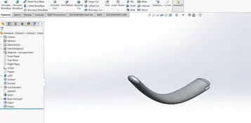
12.KICKSTAND
- FRONT VIEW
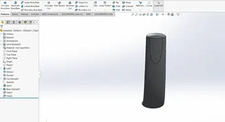
- SIDE VIEW
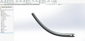
- ISOMETRIC VIEW
Tools & Features Used
- Sketch: To create required Sketch
- Line: To create continuous & construction Line
- Arc: To draw an arc
- Boss-Extrude: To obtain 3d Solid from 2D sketch
- Loft: to create Surface along Profiles
- Dome: Dome: To create dome Surface
- Split: To split Solid bodies
- Cut-extrude: To subtract a solid portion from Solid using 2D sketch
- Fillet: To convert sharp internal or external edges into smooth/round edges
- Smart Dimensions: To add /edit /delete dimension in 2D sketch
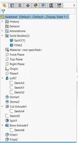
MODEL TREE
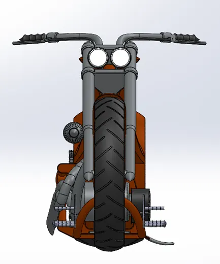
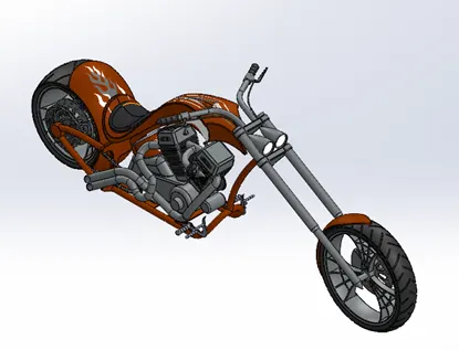
Assembly American chopper
- Front view
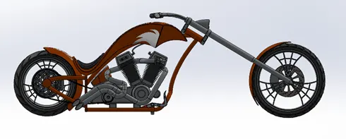
- SIDE VIEW
- ISOMETRIC VIEW
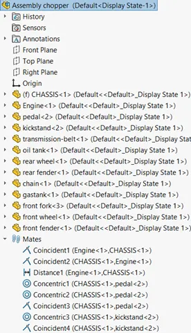
- MODEL TREE FOR ASSEMBLY
RENDERED MODEL OF AMERICAN CHOPPER
TOOLS AND FEATURES USED
- DECALS:GRAPHICS USED ON CHOPPER BODIES
- LIGHTS AND CAMERA: To adjust lighting and camera angle
- Render Preview: To preview the final render before Render
- Render: To render in required image quality
Conclusion:
Thus assembly of American chopper model has given exposure to the various design tools in solidworks for individual parts, Assembly and Rendering.