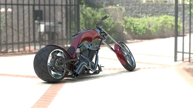
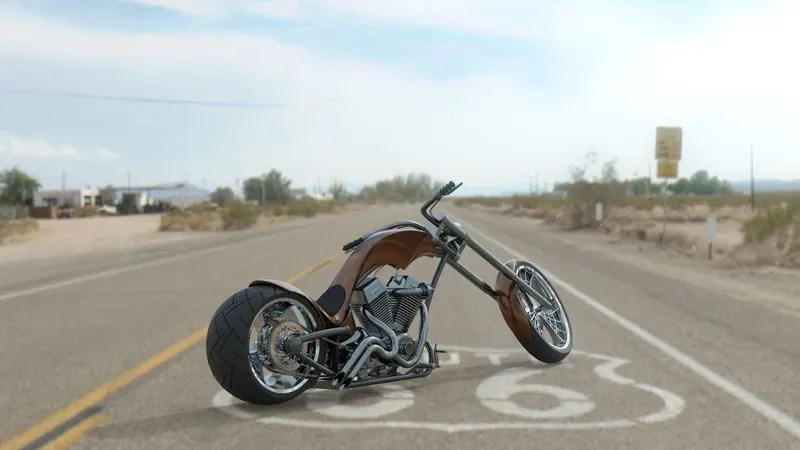
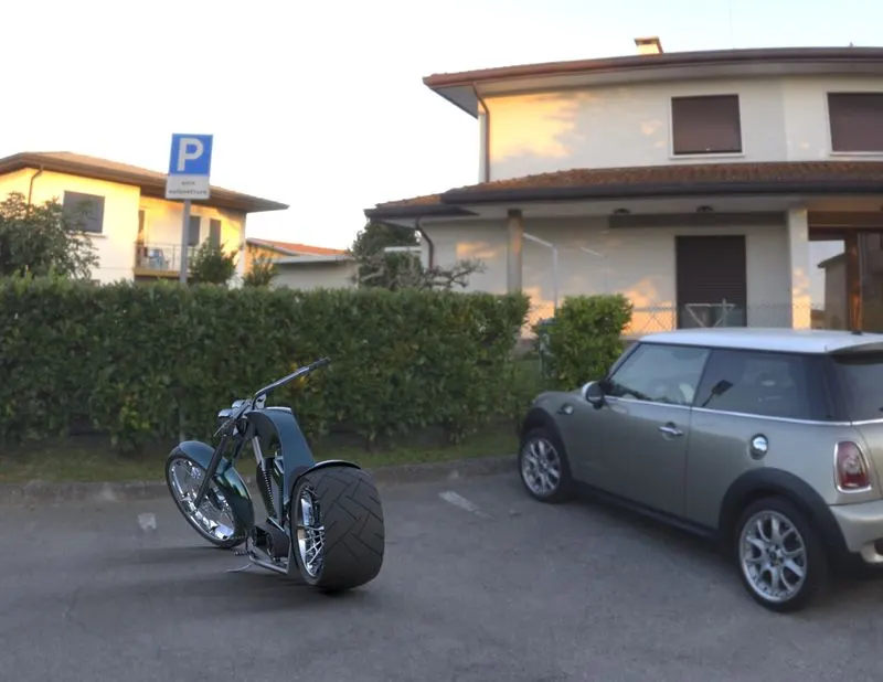
Photo Realistic Rendering
PART DESIGN AND ASSEMBLY OF AMERICAN CHOPPER
NAME :- JAAGEERI VARUN RAJU
SUBMITTED TO:- SKILL-LYNC
OBJECTIVE:-
The main objective of this project is to come across the all-basic features of solid works and to gain an ability of using solid works efficiently
- To design all the part models using solid works
- To assemble all the parts using solid works assembly
- To get all the renders and photo realistic views using PHOTO_VIEW_360 and SOLIDWORKS VISUALIZATION
INTRODUCTION TO SOME IMPORTANT TOOLS/FEATURES IN SOLIDWORKS:-
Here I'm mentioning all the features and tools that I used the modeling of American chopper.
SKETCH TOOLS: -
- Line
- circle
- rectangle
- spline
- arc
- slot
- polygon
Using all these sketch tools I develop a geometry and Sketches in 2D_plane. Most probably all the Tools basic geometry tools but I want mention about spline.
Spline: -spline is a type of tool which used to create a complex curvature it posses with some spline handles using those handles we can adjust our curvature we have to spline angle and spline weight do not to disturb the spline curvature.
3D_TOOLS: - These tools are used to convert our 2D_sketches to 3D_model/components
- Material adding tools: - These tools are used to create a 3d_solid body from 2d patterns/sketches
- Extruded boss/base: -This tool is used to add the material in such way along z axis if the 2d plane is xy
- Revolve boss/base: -This tool is used to create a model using the sketch profile and it Add's material around and along the specified axis
- swept boss/base: -This tool is used to create a model using sketch profile and path it adds the material in the shape of the sketch profile along the path line that we specified
- lofted boss/base: -This tool is used to create a model using two/more sketch profile and add the material between the sketch profiles if we provide guide curves it follows the curve
- Removal off material: -These tools are used to remove materials from a solid body
- Extruded cut: -This tool is used to cut the material in such way along z axis if the 2d plane is xy
- Revolve cut: -cuts a solid material by revolving sketch profile around a specified axis
- swept cut: -cuts the material using closed profile along the open/closed specified path
- lofted cut: -It cuts the material between two or more sketch profiles on different planes it follows the path also if we provide guide curves
- whole wizard: -it directly creates the wholes the giving type, size and depth of whole. Predefined wholes are industry standard wholes
3.Other features: - These Tools are also part of featured Tools of solid works which are mainly used to shape the edges and corners of 3d solid
- Fillet: - This tool is used to provide the curvature to the sharp edges with a radius
- Champer: -This tool is remove the material at the intersection of two edges of a solid in distance-distance method or distance-angle method
- Dome :- This tools is semishperical shape to any face of soild
- Mirror :- This tools is used to skecths or 3d models to mirror the profiles or objects about an axis,line,plane and it maintains the symmentricity if the changes in original profile /model their ia an automatic change in mirrored object
- Dynamic Mirror:-For this tool we have to predefine the mirror plane or line then changes/work at one side will automatically refelcts to other side
4.Curves and patterns
- projected curves :- It like a 3d curve which is the intersection projection of two curves on two Perpendicular planes but end points points of both sketch profiles should be coincident or verticle
- circular pattern :- This tool available both 2d and 3d in 2d it creates the patterns of selected sketch profile with a circular reference point similary in 3d it creates the patterns of featurs or solid bodies and it merges that solid bodies with the selected referance body or with whole component
- linear patterns :- This tool is also avalable in both 2d and 3d it crates the patterns in linear format with our desired distance between the elements
- Sketch driven pattern :- This tool is avaliable in only 3D to generate patterns of an 3d solid /feature along the path of a sketch profile
METODOLOGY:-
This is a cosmetic model it doesn't have any internal components/mechanisms even though we can say it as top-down approch as it is a study and uderstanding of design ascepts of all ready existed object
parts:-
1. Transmission Belt
2. Kick Stand
3. Front Fender
4. Rear Fender
5. Oil Tank
6. Chain
7. Pedal
8. Front Wheel
9. Rear Wheel
10. Front Fork
11. Chassis
12. Engine
13. Gas Tank
TRANSMISSION BELT:-
Features :- sketchtools/Extrude boss/Fillet
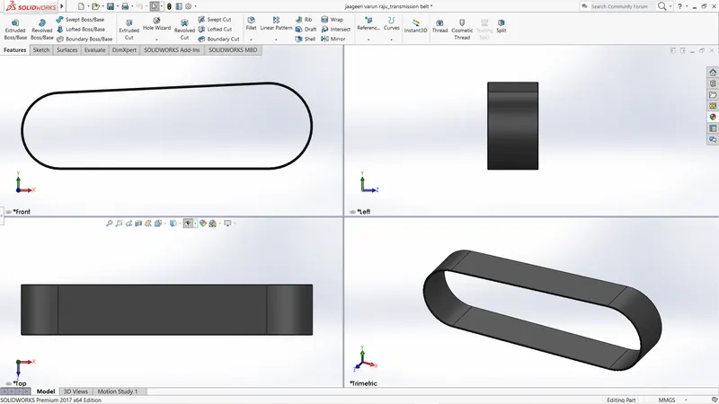
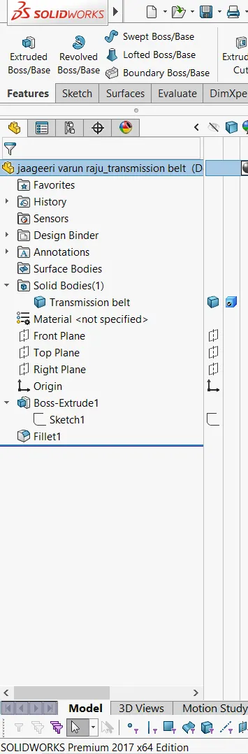
Transmision belt is used to deliver the power from power_train to gearbox
I created a sketch profile as how it is and i offset it for 3.5mm to provide thickness and extuded it.
KICK_STAND:-To provide standing a ability for easy parking
Features:-Sketch_Tools/Lofted boss/Dome
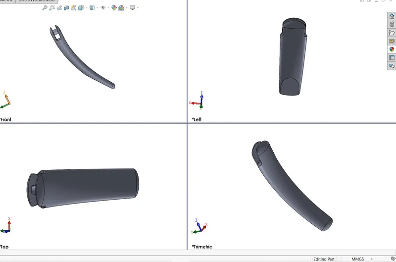
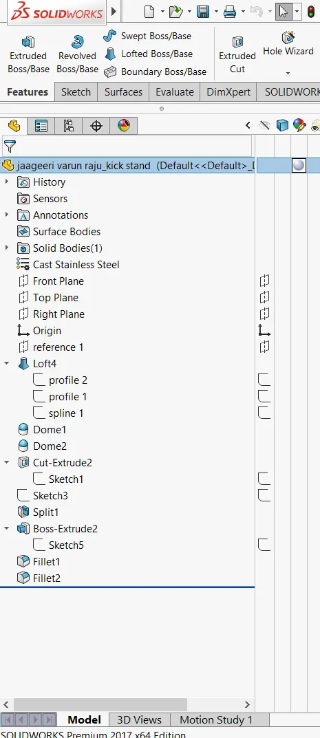
I created a spline on right plane then i created two elliptical sketch profiles on front palne and a referance which is created at the lower end of the spline and i lofted it between two sketch profiles and spline as a path
Condition :-Centre points of both the sketch profiles should coincident with spline
FRONT FENDER:-Fenders helps in areodynamics and protection from mud
Features:- Sketch Tools/Revolve boss/split/fillet/shell
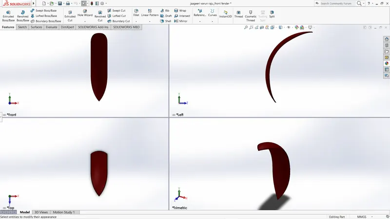
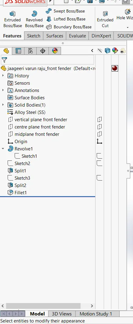
If we see the cross-of the fender in split view along y-axis we can determine the first sketch profile and i created that sketch profile and revolve it through an angle and from fron view of the solid i created two sketch at top the solid and bottom of the solid then i splited the material from the solid using split tool and those sketches as reference then we get that sharp endpoints at top and bottom of the fender and add fillet to get smooth curvature at the sharp edges and a shell at the front face to provide some clearance
REAR_FENDER:-Fenders helps in areodynamics and protection from mud
Features:-Sketch_Tools/Revolve_boss/Split/fillet/shell
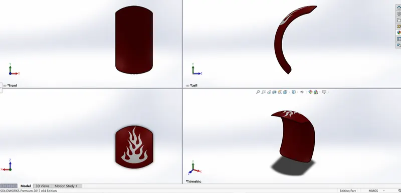
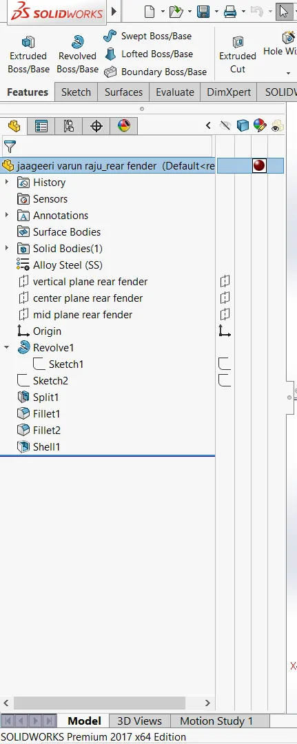
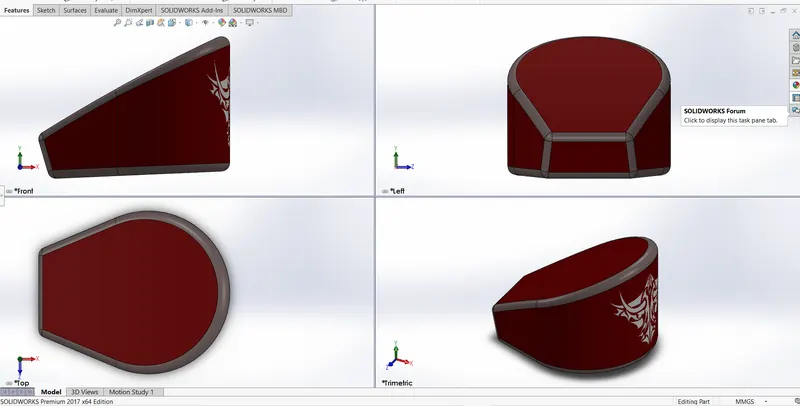
Both rear fender and front have same methodology ,If we see the cross-of the fender in split view along y-axis we can determine the first sketch profile and i created that sketch profile and revolve it through an angle and from fron view of the solid i created two sketch at top the solid and bottom of the solid then i splited the material from the solid using split tool and those sketches as reference then we get that sharp endpoints at top and bottom of the fender and add fillet to get smooth curvature at the sharp edges and a shell at the front face to provide some clearance
OIL_TANK:-For storage of oil/Gasoline
Features:-Sketch_Tools/Extrude_boss/Combine/fillet/shell
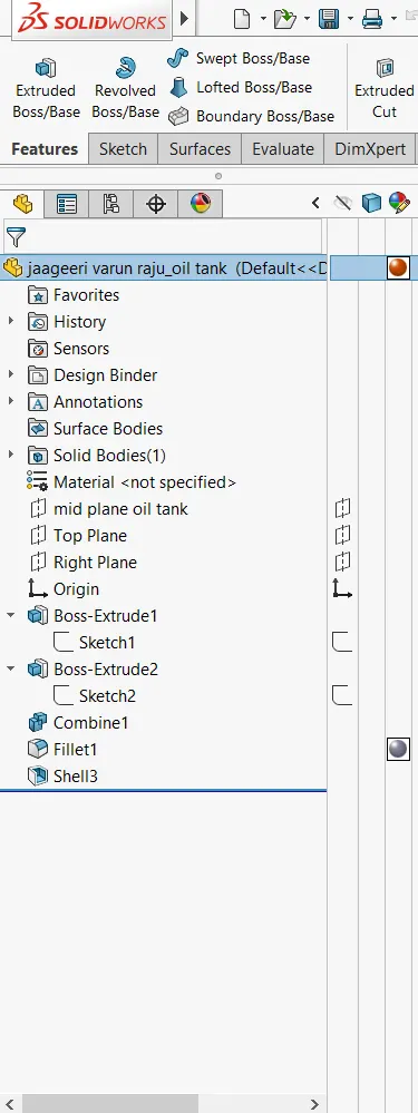
First lets see the top view of the component or solid and create a sketch profile that resembles the top view on the right_side plane and extrude it to desired size and again see the image from side view and create a sketch profile that resembles the side view on the front plane and extude it from midplane do not select merge option and combine the both solids by selecting common option then we get the we get the intersection of both solids and the remaining will be removed at the round fillet to front face and a fillet with some radius of curvature to the edges and add shell by selecting entire solid and then look the section view inside their will be no material
CHAIN:-To transmit power from Derive shaft to rear wheel in retuen the vehicle will move forward
Features:-Sketch_Tools/Sketch_blocks/sketch_driven_pattern/extrude/fillet/mirror
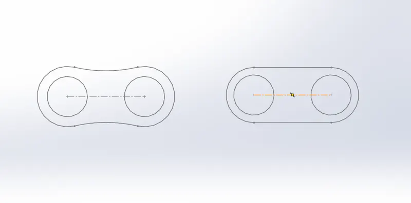
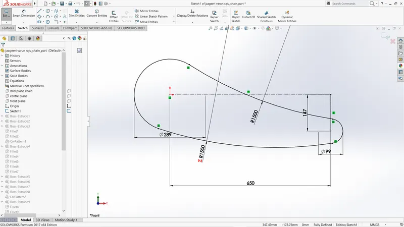
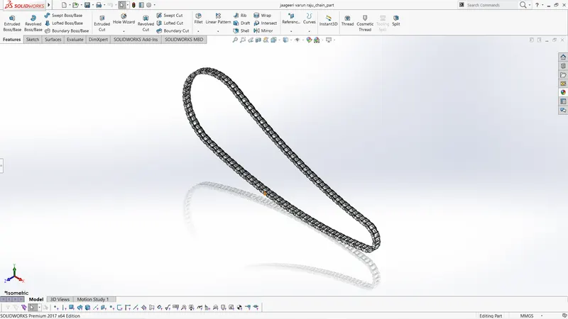
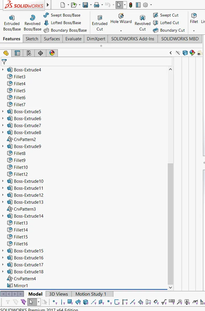
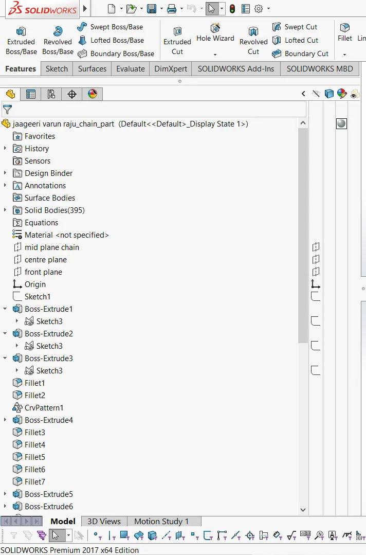
Create a sketch profile that can be used as path for sketch driven patterns and create the sketch blocks (create sketch profiles for chain links and save them as sketch blocks then we can import them into our sketch when ever we want and place them where ever we want and use them wisely for these type of pattern features and for reapeted sketch profiles) place those sketch blocks on the skecth profile 1 and extude the sketch blocks properly and use sketch driven pattern upto next point when the curvature came again place the skecth blocks and extude and use sketch driven pattern repeat this process upto attain the starting point.
PEDAL:-
FEATURES:-Sketch/Extude/Reovle/Fillet/chamfer/linear pattern
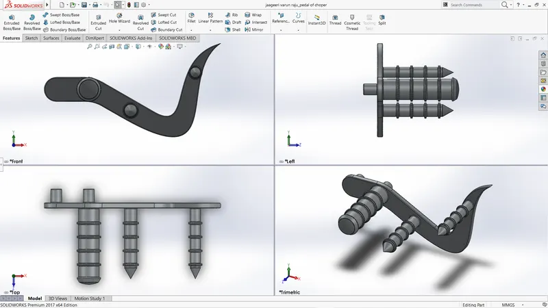
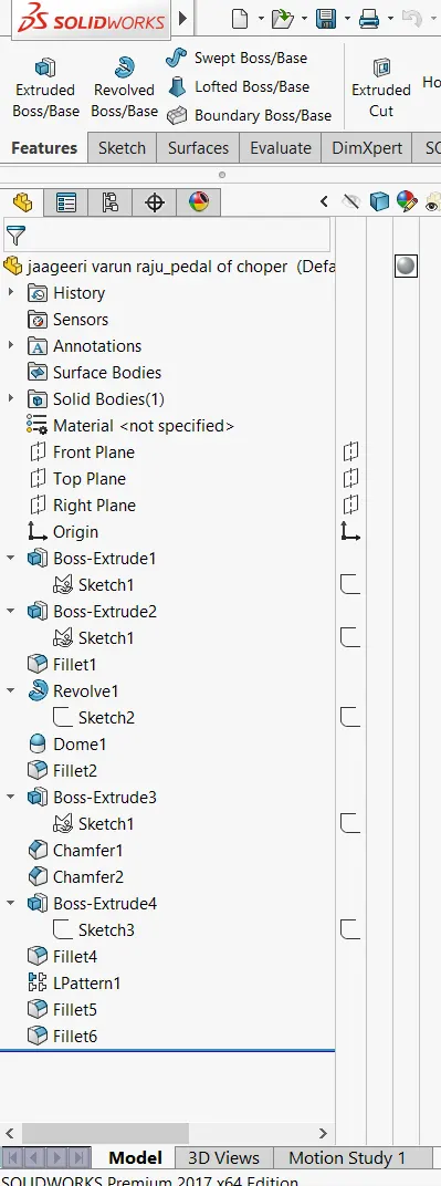
create the sketch profile like what we see from side view and extrude it from midplane and create the circular sketchs on one of the sideview faces and extrude them as in figure add chamfer to both ertrudes and for the first circular rof create a sketch profile which resembles the section of that rod on right plane and use revolve and then add dome to that revovle and create the linear pattern by creating the circular profiles which are cocentric to alrady existed circular profiles and extude at offset distance and add fillet on the other side create the circular extrudes for placement on chassis.
FRONT_WHEEL:-
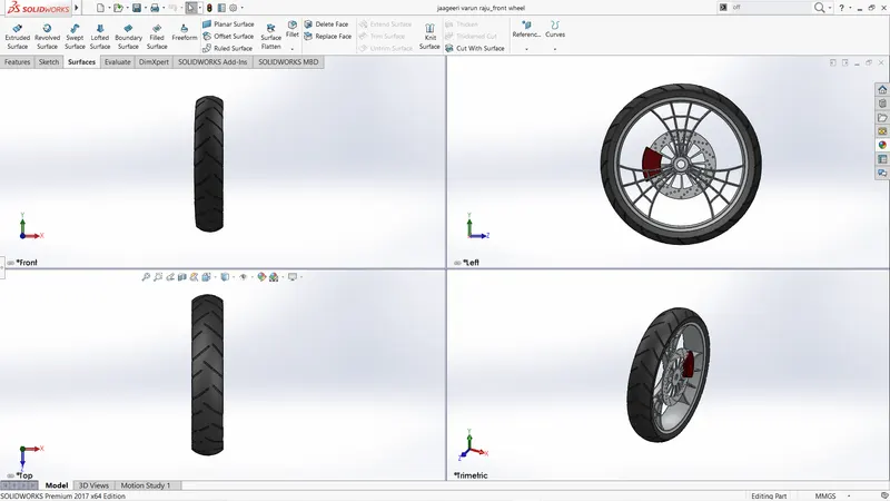
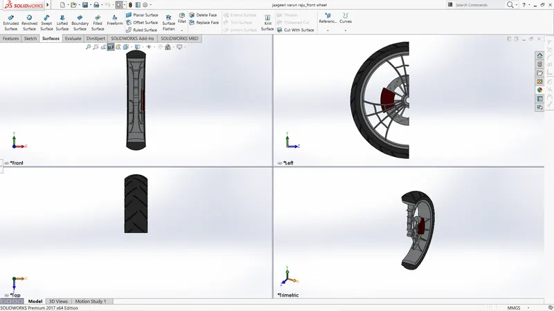
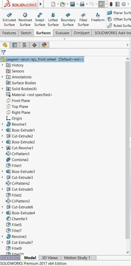
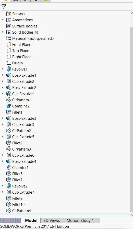
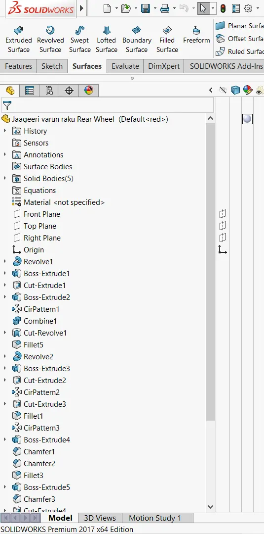
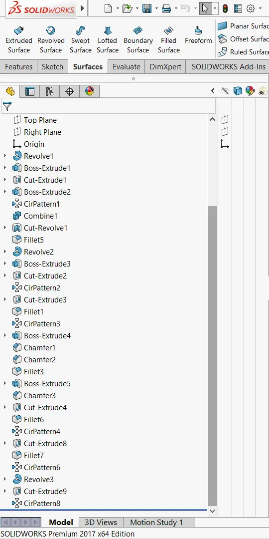
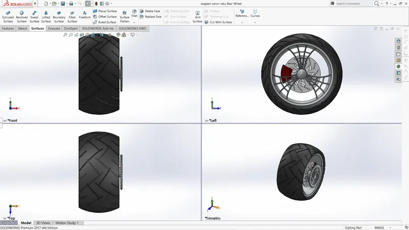
undesrstand the section view of the wheel.see the tyre and rim seperately first make the rim on front plane using revolve command and make sketch pattern of web on the samep plane and extude it from mid plane to the width of rim and copy the pattrens of web using circular pattern entities and then go to right plane make the sketch profile like what we see in the section and remove the material using revolve cut and then make the sketch profile for tyre on rignt plane and revovle it around axis of rim centre and then prepare the sketch patterns on the tyre by considering a plane at a distance and use offeset cut and copy the patterns using circular pattern entities and then add apperences.
REAR WHEEL
Rear wheel and front wheel i followed same method but in rear wheel we have to add sprocket also for that i have the consider the plane at some distane from the surface of rim.
FRONT FORK
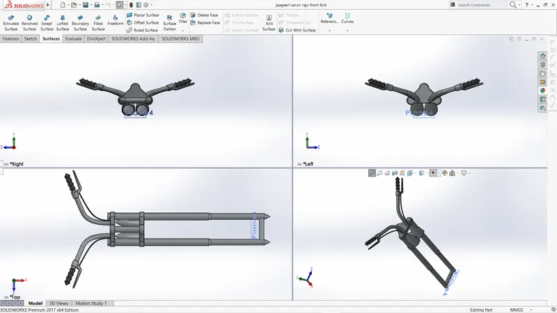
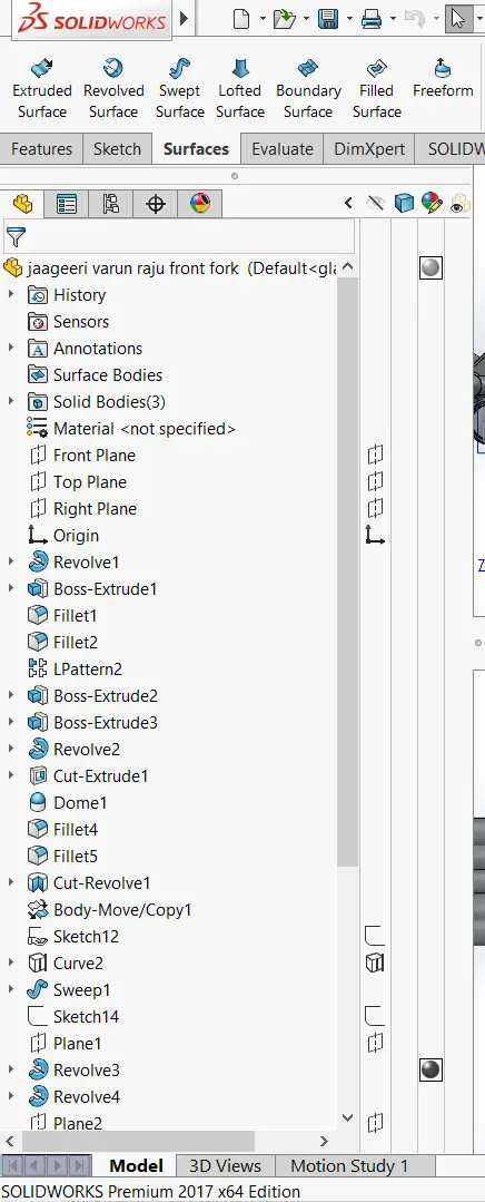
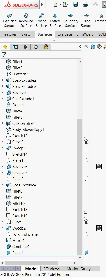
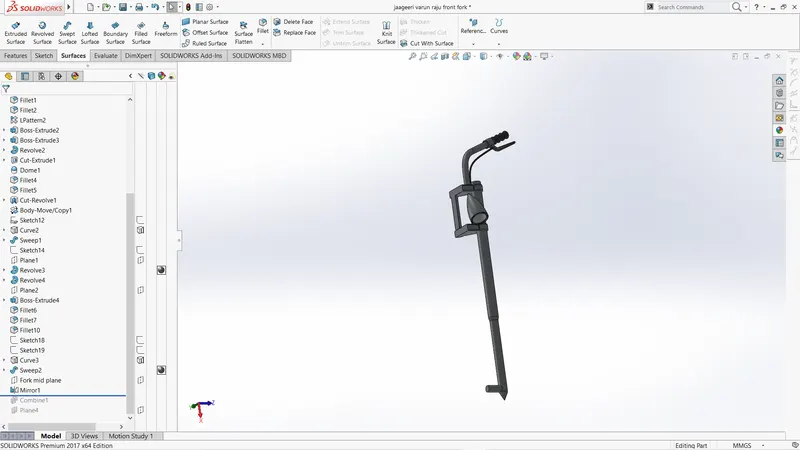
mirror/move entities/linear patterns/revolve
first I make the side of the fork using the above tools then mirrored it while mirroring got an error with headlight so that i have moved it along y axis and then add apperences.
Chassis
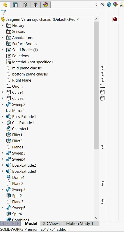
projection curves/swept boos/etrude boss/mirror
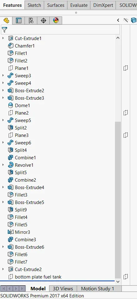
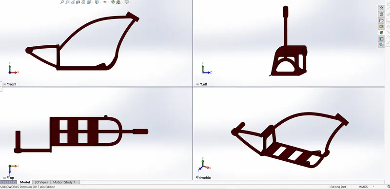
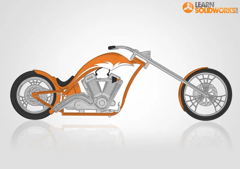
use the picture and make sketch profile of the chassis by tracing the picture and then create projection curves for the base chassis create circular profile at the end point of projection curve and use swept boss and then mirror the base and then make beams for tank placement and neck of front frok and make the plate and then hub of the wheel.
ENGINE
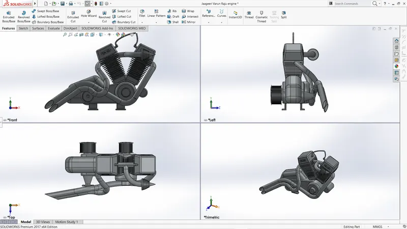
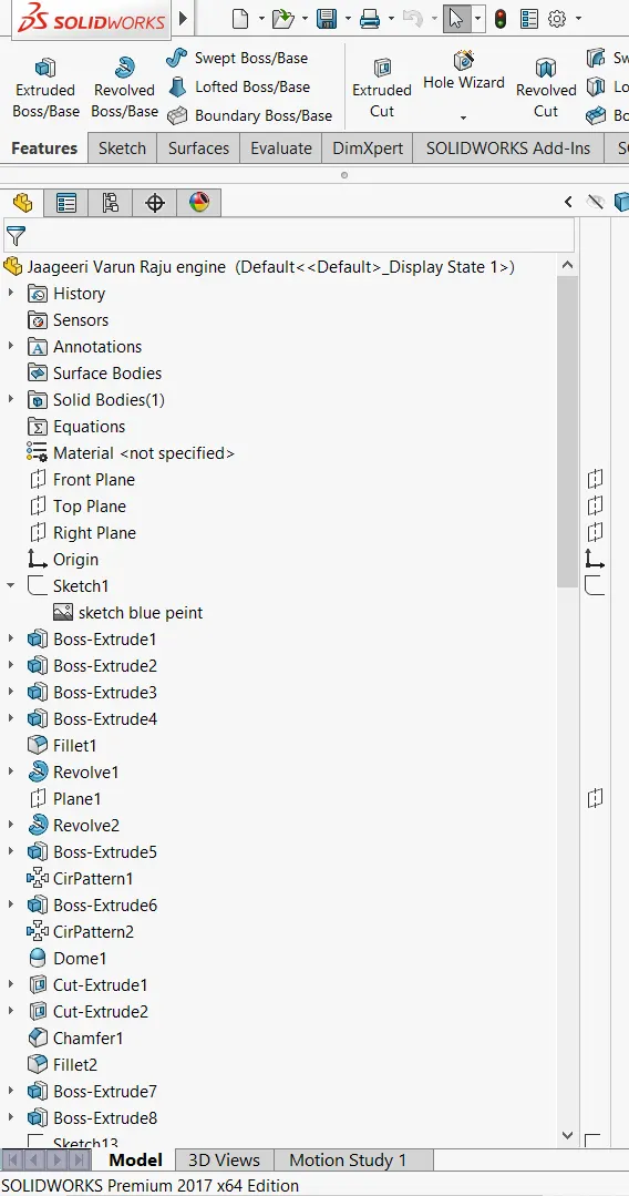
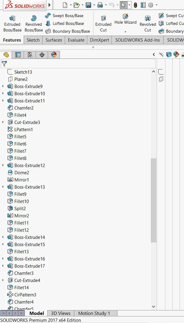
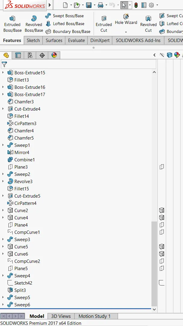
In engine we just use almost all the feartures that we come trough upto now.so,just go through the sketch picture throughly and start from mid plane make the gear box then sprocket and then pulley for transmission belt on oppostie side and then the engine blocks then exhaust and then foot pedal this is cosmetic component their is no any mechanical moments it does not follow any design constraints.and we can make the engine head/block using linear patterns and mirror features,gear box using extrude and fillets ,sprocket using extrude boss,extude cut and circular pattern entities,exhaust using projection curves and swept boss and finalli pedals by using extude and mirror to get both sides.
TANK
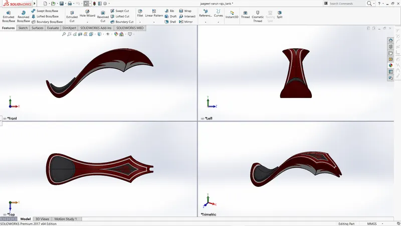
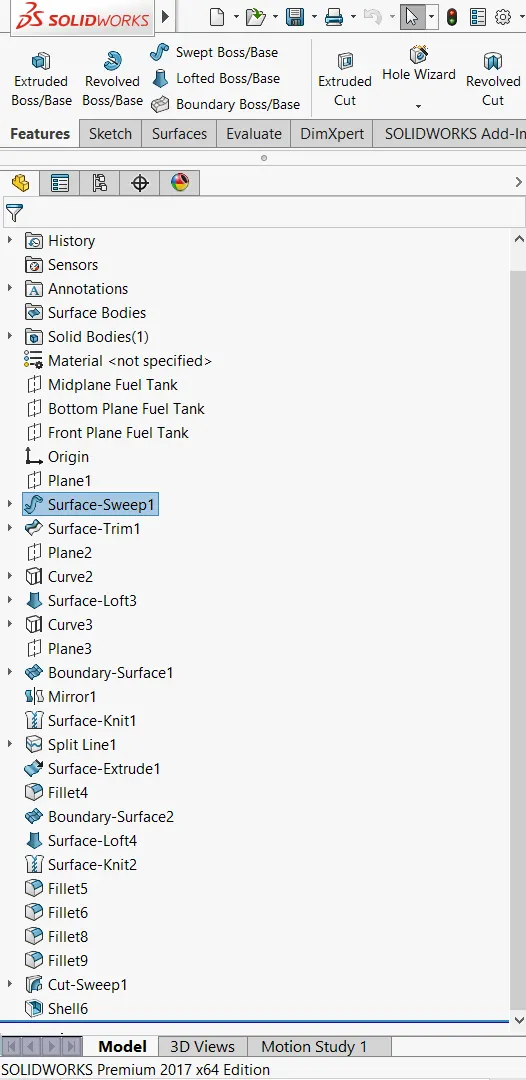
Projecttion curves /surface sweep/boundary surface/suface knit/shell/mirror
Tank is all about surfaceing here first i created half portion of the tank by creation projection curves from fron and top plane and top and bottom plane create a sweep surface using projection curve on front plane as profile along the sketch profile that traced from the skecth picture of the tank which the shape of curvature of tank,Then create projection curve for lower end of the tank and use boudary suface and the kint the surface then mirror it and create a solid using fill option then create shell to provide thickness and fillets.
ASSEMBLE:_
New-asesembly-insert components-browse all the parts
start with chassis and fix it and then assembled all the remaing parts using standard mates
- coincident
- parallel
- perpendicular
- tangent
- co_centric
- distance
- angle
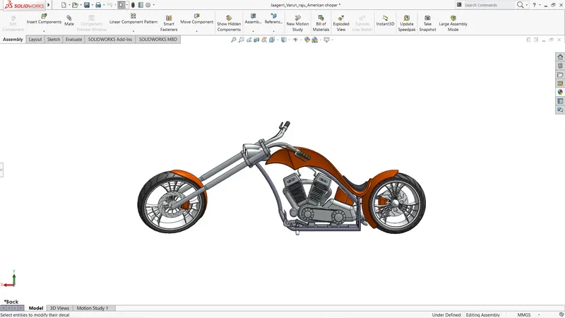
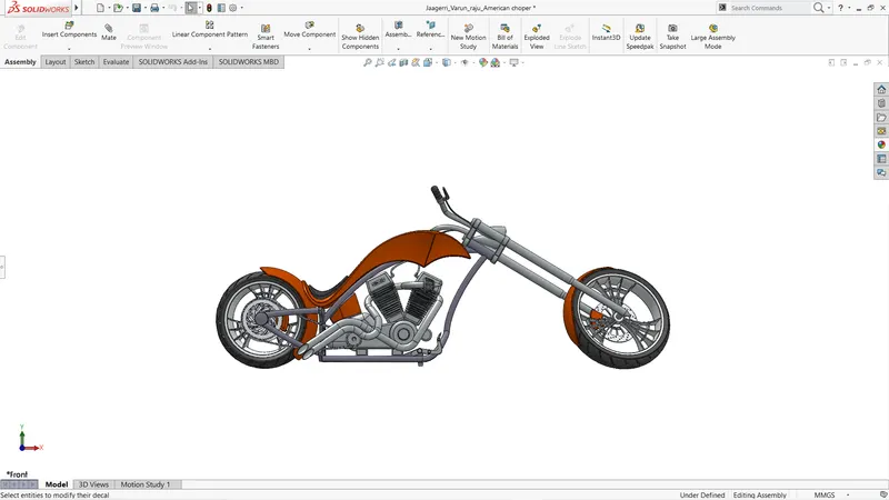
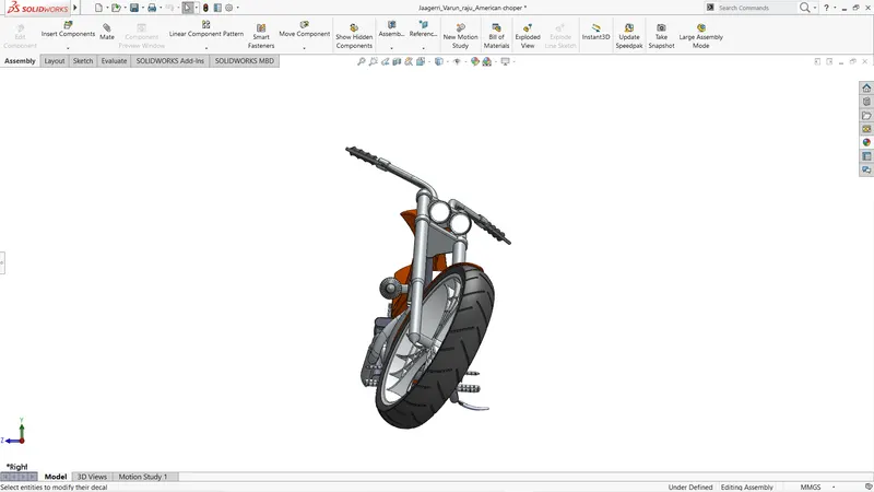
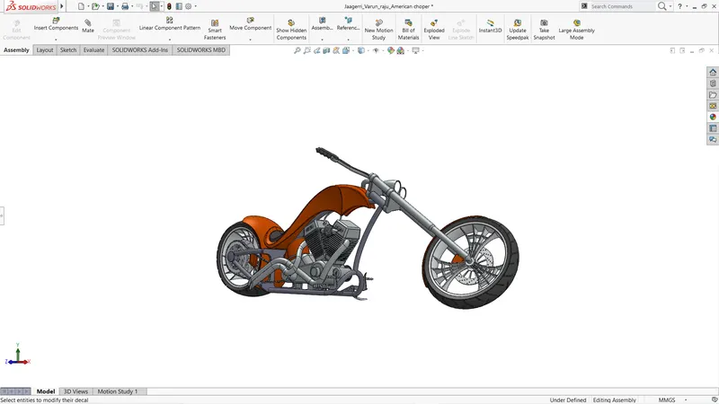
RENDERING:-renders gives a finest finish to our models and we can get as realist as possible pictures of our models by spending time and efforts and rendering is the best option to present our models as good as it can and get huge attention it also uses in colour determination and all as we incorparate original scenes into our models.
photoview 360
using photoview 360 can add decals and edit the scene and adjust intensity of shadows ,scene illumination,brightness,gamma value,bloom,and we can also add camera and direction of lights for a pariticular view and render them using final rendering option we have the options to see the preview of our rendering those are integarted preview and preview window.
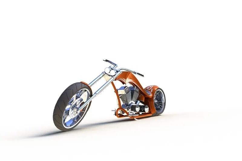
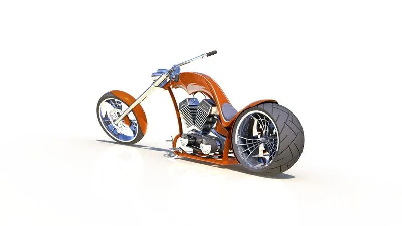
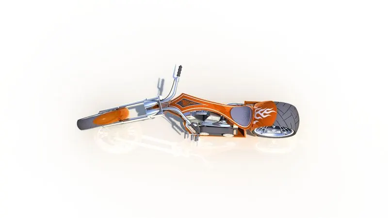
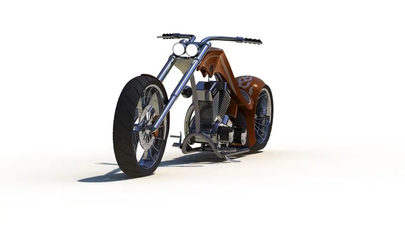
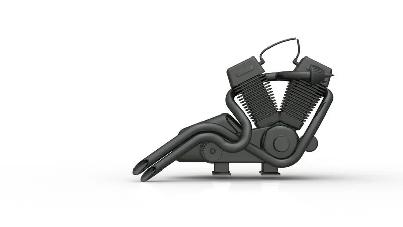
Solidworks visualization:-solidworks visualization is quite efficent than photoview 360 ,here they lot more apperences available and we put our models in 360 hdr enviroments and we get as realiastic as possible images by spending time on it.