Photo Realistic Rendering
INTRODUCTION
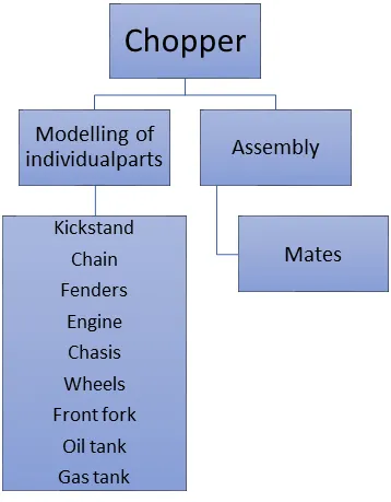
SolidWorks is a solid modelling computer-aided design (CAD) and computer-aided engineering (CAE) computer program published by Dassault Systèmes. SolidWorks is a solid modeller, and utilizes a parametric feature-based approach which was initially developed by PTC (Creo/Pro-Engineer) to create models and assemblies. Parameters refer to constraints whose values determine the shape or geometry of the model or assembly. Parameters can be either numeric parameters, such as line lengths or circle diameters, or geometric parameters, such as tangent, parallel, concentric, horizontal or vertical, etc. Numeric parameters can be associated with each other through the use of relations, which allows them to capture design intent. In this project we learnt about the detailed design of American chopper parts and assembling.
Objective:
- To create individual parts of the American chopper using solidworks according to dimensions.
- To assemble the parts into a chopper.
- To know how to use photoview 360 to render a product and make it more realistic and attractive.
KICKSTAND
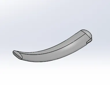
A kickstand is a device on a motorcycle that allows the bike to be kept upright without leaning against another object or the aid of a person. A kickstand is usually a piece of metal that flips down from the frame and makes contact with the ground.
Features used to create kickstand:
- Sketch
- Loft
- Dome
- Extrude boss
- Extrude cut
- Fillet
- Split
Sketch:
When you open a new part document, first you create a sketch. The sketch is the basis for a 3D model.
Loft:
Loft creates a feature by making transitions between profiles. A loft can be a base, boss, cut, or surface. You create a loft using two or more profiles. Only the first, last, or first and last profiles can be points.
Dome:
The software calculates the distance using the radius of the arc as a basis for the dome. It creates a dome that is tangent to the adjacent cylindrical or conical face.
Extrude boss/base:
An Extruded Boss/Base feature will allow you to take a 2D sketch and add thickness to it in the third dimension.
Extrude cut:
You can use the Extrude tool to remove material by projecting a sketched section normal to the sketching plane.
Fillet:
Fillet/Round creates a rounded internal or external face on the part. You can fillet all edges of a face, selected sets of faces, selected edges, or edge loops.
Split:
This tool is used to project an entity onto other surface or curved or planar faces. You can split faces on body with one command.
Procedure followed to create a model of kickstand:
- Open solidworks and create a part file
- Before creating the sketch change the default planes as follows:
- Front plane- Front plane
- Top plane - top plane
- Right plane –mid plane
- Select mid plane start the sketch.
- Then 2D sketch is created in the front plane and dimensions are given and sketch is fully defined, while sketch we use spline and trim commands.
- Create two new planes and ellipse are drawn as required to loft.
- Extrude cut is used to remove material and give space to be fastened to the frame.
- Dome feature of given radius is applied to smaller face.
- Fillets are given to smoothen sharp edges.
- Save the file by name kickstand.
TRANSMISSION BELT:
The belt that transmits the power of the engine to the driving wheels of a motor vehicle.
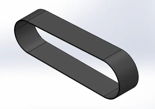
Features used to create transmission belt:
- Sketch
- Offset
- Extrude
- Fillet
- Appearances
Offset:
Offset entities takes a copy of your existing geometry and copies it at an offset. Instead of recreating geometry, you can use this to quickly sketch based on model geometry. Offset entities is a great tool for enlarging or shrinking your sketch geometry.
- Open solidworks and create a part file
- Then, select the front plane and sketch
- Fully sketch is created according to dimensions on the front plane.
- Sketch is extruded to create a 3D body.
- Fillets are given to make sharp edges smooth, which helps in lessening the wear of belt.
- Model is saved as transmission belt.
FRONT FENDER:
The front fender is the mounted on the front fork above the wheel to protect the rider and the chopper other parts from the debris foreign particles.
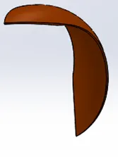
Features used to create front fender:
- Sketch
- Offset entities
- Trim entities
- Revolve
- Dynamic mirror
- Split
- Appearances
Revolve:
Revolved Boss or Base is a SolidWorks feature tool which is used to create solid 3D model around an axis. You can revolve the sketch around an axis to add materials to it.
Dynamic mirror:
Dynamic mirror is similar to mirror entities however the line or lines to mirror about are selected beforehand then anything drawn in the sketch will be mirrored dynamically.
Rear fender:
The rear fender mounted on the chassis and above the rear wheel at a certain angel.
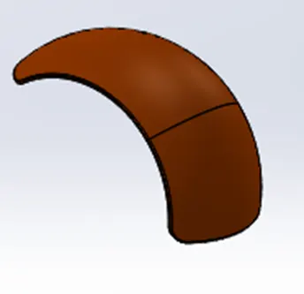
Features used to model rear fender:
- Sketch
- Offset entities
- Trim entities
- Revolve
- Appearances
Chain:
Chain and sprockets are some of the most important parts of a motorcycle drivetrain and their maintenance is a crucial part of safe riding. Transmits power from engine to the rear wheel.
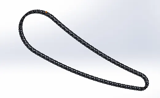
Features used to create chain
- Sketch
- Trim
- Fillet
- Blocks
- Extrude
- Patterns
- Appearances
Trim entities:
Trims open sketch entities that lie inside two bounding entities. Trims open sketch entities outside of two bounding entities.
To make blocks:
- Create a sketch
- Select make block option(tools>blocks>make block)
- Select the entities you want to include in the block entities.
- Save it
- Repeat steps 2-4 for another block
- With the sketch in edit mode, and necessary relations
- Save the part file.
Patterns:
The Curve Driven Pattern tool allows you to create patterns along a planar or 3D curve. To define the pattern, you can use any sketch segment, or the edge of a face (solid or surface), that lies along the plane. You can base your pattern on an open curve, or on a closed curve, such as a circle.
OIL TANK:
A fuel tank (also called a petrol tank or gas tank) is a safe container for flammable fluids. Though any storage tank for fuel may be so called, the term is typically applied to part of an engine system in which the fuel is stored and propelled (fuel pump) or released (pressurized gas) into an engine.. It is a hollow one. The thickness of the oil tank is given by 3mm in our model.
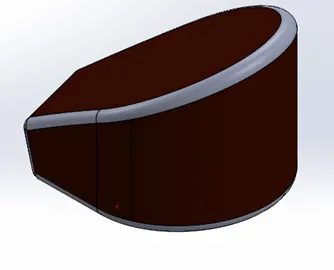
Features used to create oil tank:
- Sketch
- Boss extrude
- Combine
- Fillet
- Shell
Shell:
The shell feature is used to define the thickness of thin and thick shell elements.
Combine:
Combine feature is used to manually combine two bodies like add, subtract etc.
PEDAL:
Pedal is an external part attached to the chassis. The pedal is used to place the leg on top of that to give comfort to the rider.
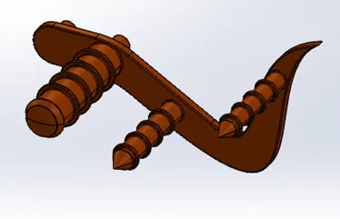
Features used to create pedal:
- Sketch
- Extrude
- Fillet
- Linear pattern
- Dome
- Chamfer
Chamfer:
A cut on edge or corner of something that makes it slope slightly rather being perfectly square.
Linear pattern:
It is also same as circular pattern. The feature or the bodies are patterned linearly.
FRONT WHEEL:
A wheel is a circular block made of steel/alloy material. On the top of wheel, the tire is covered. The tire is made of rubber and it has thin wires within it.
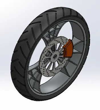
Features used to create front wheel:
- Sketch
- Revolve
- Trim
- Fillet sketch
- Boss extrude
- Revolve cut
- Linear pattern
- Chamfer
- Cut extrude
- Circular pattern
Circular pattern:
Circular pattern is used to create a pattern of spokes and the pattern of groves available in the tire. It is also used to create holes in the discs of the front wheel. The parent/features are used to create number of instances required to create the pattern circularly.
REAR WHEEL:
A circular object that revolves on an axis and is fixed below a vehicle.
The disc and sprocket are connected with rear wheel.
The chain is connected between the engine and rear wheel.
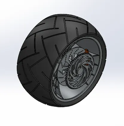
Features used to create rear wheel
- Sketch
- Revolve
- Trim
- Sketch fillet
- Extrude
- Planes
- Revolved cut
- Linear pattern
- Chamfer
- Fillet
- Extrude cut
- Circular pattern
FRONT FORK:
Most motorcycles today use telescopic forks for the front suspension. The forks can be most easily understood as simply large hydraulic shock absorbers with internal coil springs. They allow the front wheel to react to imperfections in the road while isolating the rest of the motorcycle from that motion.
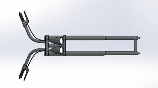
Features used to create front fork:
- Sketch
- Extrude
- Trim
- Revolve
- Split
- Move/copy bodies
- Dome
- Mirror
- Combine
- Projected curve
- Sweep
Move/copy bodies:
This feature is used to move/copy the body from one place to another place.
Mirror:
By using mirror faces with a midplane selected only the chosen faces within the revolve will be mirrored. Mirroring bodies can be used whether in a single or multibody part and allows you to select solid geometry instead of the features and faces in a body. In the fork part the one part is created and the other part is mirrored. Then the parts are manually combined.
Projected curve:
Projected curve is a kind of 3D curve which is projected based on the two different 2D sketches.
Sweep:
With the sweep feature we can create a shape by moving a 2D sketch along a 2D or 3D sketch path.
CHASSIS:
A chassis or a frame forms its skeleton. All the components of a motorcycle like suspension, wheels fuel tank, seats, handle bars etc. are attached to this base structure which lends a motorcycle its strength and ability to handle well.
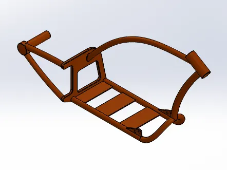
Features used to create chassis:
- Sketch
- Offset
- Convert entities
- Project curve
- Trim
- Sweep
- Split
- Revolve
- Cut extrude
- Fillet
- Combine
ENGINE:
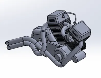
Cylinders. Motorcycle engines can have between one and six cylinders. For years, the V-twin design was the engine of choice for motorcycle engineers in America, Europe and Japan. The V-twin gets its name from the fact that the two cylinders form a V shape, such as the classic Harley-Davidson V-twin shown below.
Features used to create engine:
- Sketch
- Trim
- Revolve
- Boss extrude
- Extrude cut
- Offset
- Dome
- Fillet
- Projected curve
- Composite curve
- Sweep
- Mirror
- Circular pattern
- Split
Composite curve:
This feature is used to join two curves and make them a single curve.
GAS TANK:
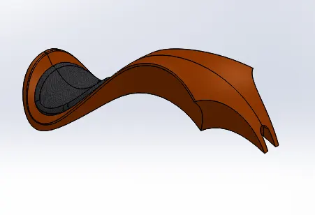
Gas tanks are used to store gas and its gives gas to the engine when required.
Features used to create gas tank
- Trim
- Projected curve
- Sweep surface
- Loft surface
- Fill surface
- Surface trim
- Surface knit
- Sweep cut
- Fillet
Loft surfaces:
Loft surfaces are surfaces generated by multiple 3D curves or existing edges creating a smooth tangency between the selected curves.
Fill surface:
The Filled Surface feature constructs a surface patch with any number of sides, within a boundary defined by existing model edges, sketches, or curves, including composite curves.
Surface trim:
You can use a surface, plane, or sketch as a trim tool to trim intersecting surfaces. You can also use a surface in conjunction with additional surfaces, as mutual trim tools.
Knit surface:
The Knit Surface tool is used to combine two or more faces and surfaces into one.
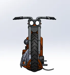
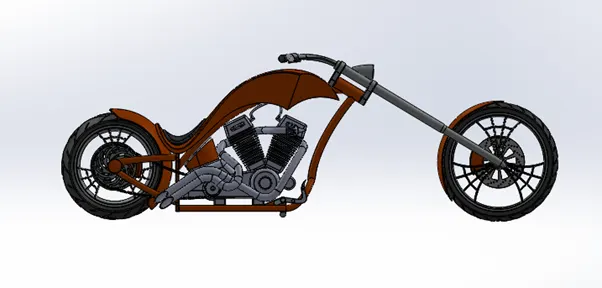
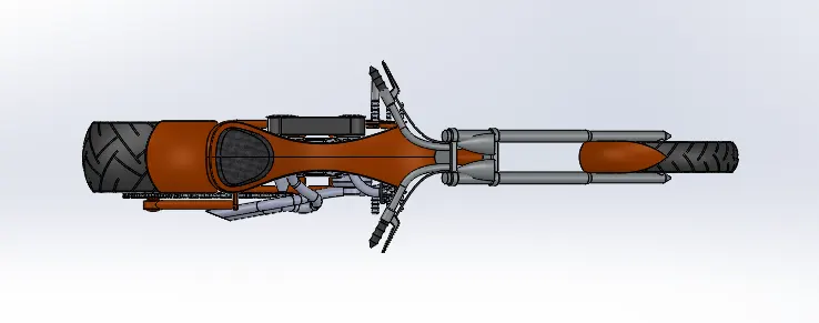
ASSEMBLY OF THE CHOPPER:
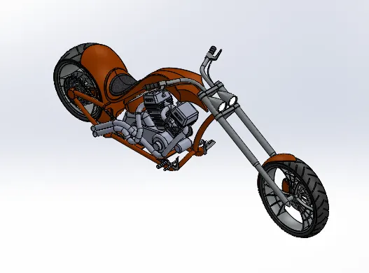
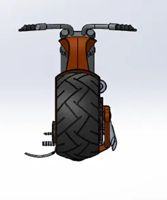
- Initially the chassis part is inserted in the assembly by using insert parts in the option. After that the part is inserted in the assembly environment and click ok to fix the chassis.
- After that other parts of the chopper are inserted into the assembly and given possible mate conditions.
Features used to assemble chopper:
- Insert parts
- Mates
Mates:
Mates create geometric relationships between assembly components. As you add mates, you define the allowable directions of linear or rotational motion of the components. You can move a component within its degrees of freedom, visualizing the assembly's behaviour.
Some examples include:
- A coincident mate forces two planar faces to become coplanar. The faces can move along one another, but cannot be pulled apart.
- A concentric mate forces two cylindrical faces to become concentric. The faces can move along the common axis, but cannot be moved away from this axis.
CONCLUSION:
- Modelling the parts of the chopper
- Inserted the parts with required mates
- Created a well-defined assembly.